In this post we will try to learn how to diagnose and repair an inverter, by comprehensively learning the various stages of an inverter, and how a basic inverter functions.
Before I have explained how to repair an inverter it would be important for you to first get fully informed regarding the basic functioning of an inverter and its stages. In the following content I have explained regarding the important aspects of an inverter.
Stages of an Inverter
As the name suggests DC to AC inverter is an electronic device which is able to "invert" a DC potential normally derived from a lead-acid battery into a stepped-up AC potential. The output from an inverter are normally quite comparable to the voltage that is found in our domestic AC Mains outlets.
Repairing sophisticated inverters are not easy due to their many involved complex stages and requires expertise in the field. Inverters which provide sine wave outputs or the ones which use PWM technology to generate modified sine wave can be difficult to diagnose and troubleshoot for the folks who are relatively new to electronics.
However, simpler inverter designs that involve basic operating principles can be repaired even by a person who is not specifically an expert with electronics.
Before we move into the fault finding details it would be important to discuss how does an inverter work and the different stages normally an inverter may comprise:
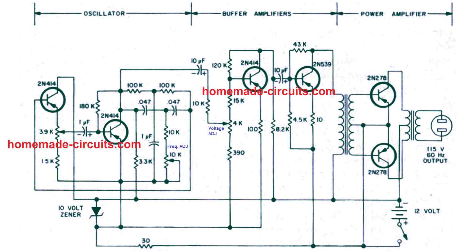
An inverter in its most basic form may be divided into three fundamental stages viz. oscillator, driver and the transformer output stage.
Oscillator:
This stage is basically responsible for the generation of oscillating pulses either through an IC circuit or a transistorized circuit.
These oscillations are basically the productions of alternate battery positive and negative (ground) voltage peaks with a particular specified frequency (number of positive peaks per second.) Such oscillations are generally in the form of square pillars and are termed as square waves, and the inverters operating with such oscillators are called square wave inverters.
The above generated square wave pulses though are too weak and can never be utilized to drive high current output transformers. Therefore these pulses are fed to the next amplifier stage for the required task.
For info on Inverter oscillators you can also refer to the complete tutorial which explains how to design an Inverter from the scratch
Booster or Amplifier (Driver):
Here the received oscillating frequency is suitably amplified to high current levels using either power transistors or Mosfets.
Though the boosted response is an AC, it is still at the battery supply voltage level and therefore cannot be used to operate electrical appliances which work at higher voltage AC potentials.
The amplified voltage is therefore finally applied to the output transformer secondary winding.
Output Power Transformer:
We all know how a transformer works; in AC/DC power supplies it is normally used to step-down the applied input mains AC to the lower specified AC levels through magnetic induction of its two windings.
In inverters a transformer is used for similar purpose but with just opposite orientation, i.e. here the low level AC from the above discussed electronic stages is applied to the secondary windings resulting in an induced stepped up voltage across the primary winding of the transformer.
This voltage is finally utilized for powering the various household electrical gadgets like lights, fans, mixers, soldering irons etc.
Basic Principle of Operation of an Inverter
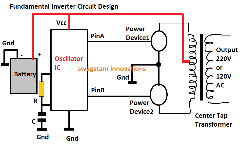
The above diagram shows the most fundamental design of an inverter, the working principle becomes the back bone for all conventional inverter designs, from the simplest to the most sophisticated ones.
The functioning of the shown design may be understood from the following points:
1) The positive from the battery powers the oscillator IC (Vcc pin), and also the center tap of the transformer.
2) The oscillator IC when powered starts producing alternately switching Hi/lo pulses across its output pins PinA and PinB, at some given frequency rate, mostly at 50Hz, or 60Hz depending as per the country specs.
3) These pinouts can be seen connected with the relevant power devices #1, and #2, which could be mosfets or power BJTs.
3) At any instant when PinA is high, and PinB is low, the Power Device#1 is in the conducting mode, while Power Device#2 is held switched OFF.
4) This situation connects the upper tap of the transformer to ground via the power device#1, which in turn causes the battery positive to pass through upper half of the transformer, energizing this section of the transformer.
5) Identically, in the next instant when the pinB is high and PinA is low, the lower primary winding of the transformer becomes activated.
6) This cycle repeats continuously causing a push-pull high current conduction across the two halves of the transformer winding.
7) The above action within the transformer secondary causes an equivalent amount of voltage and current to switch across the secondary by means of magnetic induction, resulting in the production of the required 220V or the 120V AC across the secondary winding of the transformer, as indicated in the diagram.
DC to AC Inverter, Repairing Tips
In the above explanation a couple of things become very critical for obtaining correct results from an inverter.
1) First, the generation of the oscillations, due to which the power MOSFETs are switched ON/OFF, initiating the process of electromagnetic voltage induction across the primary/secondary winding of the transformer. Since the MOSFETs switch the primary of the transformer in a push-pull manner, this induces an alternating 220V or 120V AC across the secondary of the transformer.
2) The second important factor is the frequency of the oscillations, which is fixed as per the country’s specifications, for example countries that supply 230 V, generally have a working frequency of 50 Hz, in other countries where 120 V is specified mostly work at 60 Hz frequency.
3) Sophisticated electronic gadgets like TV sets, DVD players, computers etc. are never recommended to be operated with square wave inverters. The sharp rise and fall of the square waves are just not suitable for such applications.
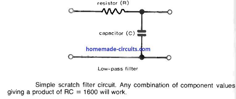
4) However there are ways through more complex electronic circuits for modifying the square waves so that they become more favorable with the above discussed electronic equipment.
Inverters using further complex circuits are able to produce waveforms almost identical to the waveforms available at our domestic mains AC outlets.
How to Repair an Inverter
Once you get well versed with the different stages normally incorporated in an inverter unit as explained above, troubleshooting becomes relatively easy. The following tips will illustrate how to repair DC to AC inverter:
Inverter is “Dead”:
If your inverter is dead, do preliminary investigations such as checking battery voltage and connections, checking for a blown fuse, lose connections etc. If all these are OK, open the inverter outer cover and do the following steps:
1) Locate the oscillator section; disconnect its output from its MOSFET stage and using a frequency meter confirm whether or not it is generating the required frequency. Normally, for a 220V inverter this frequency will be 50 Hz, and for 120V inverter this will be 60 Hz. If your meter reads no frequency or a stable DC, it may indicate a possible fault with this oscillator stage. Check its IC and the associated components for the remedy.
2) In case you find the oscillator stage working fine, go for the next stage i.e. the current amplifier stage (power MOSFET). Isolate the MOSFETS from the transformer and check each device using a digital multimeter. Remember that you may have to completely remove the MOSFET or the BJT from the board while testing them with your DMM. If you find a particular device to be faulty, replace it with a new one, and check the response by switching ON the inverter. Preferably connect a high wattage DC bulb in series with the battery while testing the response, just to be on the safer side and prevent any undue damage to the battery
3) Occasionally, transformers can also become the major cause for a malfunction. You can check for an open winding or a loose internal connection in the associated transformer. If you find it to be suspicious, immediately change it with a new one.
Although it won't be that easy to learn everything about how to repair DC to AC inverter from this chapter itself, but definitely things will start "cooking" as you delve into the procedure through relentless practice, and some trial and error.
Still have doubts...feel free to post your specific questions here.

Questions & Answers
Sir,
I understand that the Inverter primary winding will have 4 terminals, 2 outers go to mosfets (power device 1 & 2), center tap being divided into 2 ends with one end being directly connected with oscillator IC KA3525A then power amplifier IC LM324N, then then Pin-11 & Pin-13, then routed to gates of mosfets. My queries are:- (1) Can I connect negative terminal of battery with ‘GND’ marked leg/pin in PCB for cooling fan input. I find no other GND/COMMON marked point in PCB ? Under this circumstance, can I connect negative terminal of battery directly to either any source of mosfet or GND Pin-13 of Oscillator IC ? (2) In my purchased Inverter circuit of model DX028, there are 3 6-pin & 1 2-pin(fan) male connectors. Please inform me of which 2 out of 3 6-pin connectors are to jumped together with female terminal. Best regards.
Hi Muhammad,
Yes the battery negative must connect to the common GND line of the PCB. You can connect it to the fan GND point, MOSFET source line, or the IC ground line, since all should be electrically common in the inverter circuit. However, please confirm continuity with a multimeter before connecting.
Regarding the 6-pin connectors of DX028, different manufacturers may use different jumper arrangements, so without seeing the PCB markings or circuit layout it is difficult to identify which two connectors must be shorted. Please check the PCB labels or share a clear photo of the board.
i want to build a 10.000 kw or 15,000 kw pure wave inverter to run a off he grid little home need help thx
hernandez6984@rocketmail.com
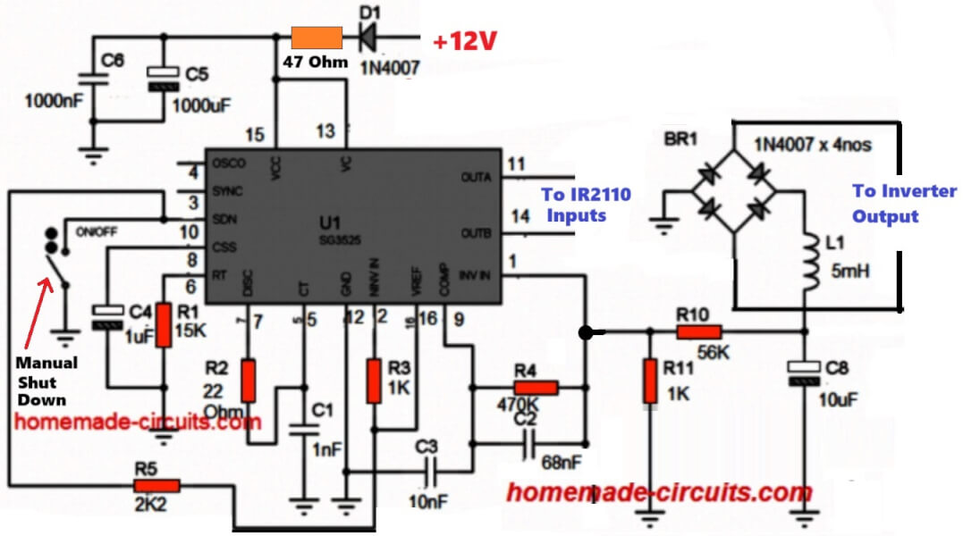
Pls how to convert PWM using SG3524N to pure sine wave inverter. Pls circuit diagram
Thanks sir
Hi Dady, that’s not possible. To convert it into sine wave you will need an external chopper:
Pls kindly explain how to use the chopper and other to convert it into sine wave. If possible please share the diagram
Thanks
The complete tutorial is explained in the following article:
https://www.homemade-circuits.com/sg3525-pure-sinewave-inverter-circuit/
Hi swagtam
How are you doing today? Guess you riding high on the electronic hobby field?
I have a faulty battery charger that is damaged due to over charge current on the battery. It uses oscillating switching design. It’s main components are single 2sk2082 mosfet and uc3845b pwm drive ic. The mosfet damage and fuse cut.
Have change d mosfet and ic yet no sign of oscillating on the primary side of the tx to send to the sec side. The cct is silent with no response. There no other major component to change. Is there any other like component causing this issue like smd resistor?
Am confused on wats going on, on this small oscillating power battery charger dual volt model.
Please kindly guide.
Thank you.
Yes have already checked d processor v from the vreg and it’s 5v but while proc goes hot d vreg begins to reduce v to as low as 1v or no v. Have changed vreg with no difference but I will try other suggestions but I suspect d proc itself. But ds is strange never seen a proc go bad like hardware failure.
Thanks
Ok, great, please also check by disconnecting all the output devices from the microcontroller, if it still heats up then certainly the IC has gone bad…
Finally have found why the oscillating power cct bat charger refused to work after fixing mosfet. The 20ohm biase resistor was damage. So I fixed a 22ohm available resistor and it works but with a vibrating noise on the ferrite tx for a short time and mosfet pops again.
So wats causing the tx to vibrate with spike noise which damage the mosfet?
Could d wrong value resistor be the fault or tx is shorting inside ?
Thank you
The MOSFET gate resistor value is not critical, and 22 ohms looks OK to me.
Without seeing the complete schematic it could be difficult to judge the actual fault…
Hi swagtam
Guess you doing great?
Please I need detailed explanation on what’s going on with an inverter here. The inverter has been working fine over 6months after installation but suddenly stop working no output when no damage inside.
After interrogation I found out that the inverter has no component damage but when sw on the inverter tries to start but immediately goes off in like 5 sec. I finally found out that the microprocessor is the fault. The processor goes very hot under 5 sec and inv goes off immediately. But if a fan is focus on the processor it makes inverter works for a short period.
What can be the cause. The microprocessor or components around the processor?
Thanks
Hi Daniel, Can you please check the supply voltage across the microprocessor, I guess it should be 5V. If the voltage is correctly regulated for the microprocessor, then check its performance by disconnecting all the devices associated with the output pins of the microprocessor…now if it still gets hot, then the IC itself could be faulty.
Thank you Daniel,

It can be difficult to pin-point the fault without a thorough checking of the board.
However, you will find that the board also includes a few other semiconductor devices also like BJTs ,and diodes, so i would recommend you to change those also and then check the response.
Always connect a 40 watt incandescent bulb in series while doing theses tests for extra safety.
Okay, I’m waiting for a diagram from you. Thank you so much for helping
I have already given you the diagrams through my previous emails…do you want the Arduino based diagrams?…
The instructor doesn’t allow me to use Arduino — only standalone ICs are allowed.
I searched for the best option and found that SG3525 or UC3525 are among the top choices.
If you have any other suggestions, I’d really appreciate your feedback
In that case I would recommend using the 4047 IC instead of the SG3525 which may be an overkill for a simple square wave inverter.
The shut down features can be adjusted inside the H-Bridge ICs itself.
How to make feedback and add cooling, how to get a clean sine?I have uc3525 and ir2110. I asked you recently, you just sent me a photo.
Yes I can only send a circuit diagram, not anything more…for sine wave you will have to use an Arduino, with any other method the output will not be a proper sine wave. Feedback is already included in my previous circuits diagrams
Hello, it’s me again.
Yesterday you asked me to explain the problem in detail, but I don’t think I’ll be able to describe everything clearly in a long text — so I’ll try to explain briefly what I’ve done so far.
I’m using the UC3525 chip along with one IRF2101 driver. An AI tool suggested that I actually need two drivers, but even after trying that, I couldn’t fix the issue in Proteus.
For the power stage, I used four IRFP4668 MOSFETs in a half-bridge configuration.
The feedback was implemented through a PC817 optocoupler.
The input voltage is supposed to support a wide range from 12V to 24V, and the output should be 230V, 50Hz, 500W with a pure sine wave.
Unfortunately, the whole system doesn’t work, and I don’t understand why.
If it’s not too much trouble, could you please help me by creating a correct and functional circuit, this time using the SG3525 and IR2110 driver, with all the necessary protections and cooling?
I would be very grateful if you could also explain why each component is connected the way it is, as I’m just a hobbyist in electronics and I really want to build a professional and reliable inverter for home use.
Hi, Surely I can give you the full inverter diagram using the SG3525 and IR2110 ICs, but why not use an Arduino instead of the SG3525, which will then allow you to get a sine wave output…
https://www.homemade-circuits.com/arduino-h-bridge-sine-wave-inverter-circuit/
Let’s better sg3525, I still stand my ground, please show me how to connect ir2110, irpf4668 A half bridge. For feedback to the optocoupler, with all protections and a motor for cooling. If you explain everything, I would be very, very grateful.
Sure! you can combine the following two designs to complete the project. Build them separately and test them separately, then once confirmed you can integrate them for the final results. For the IR2110, the load can be a transformer or the appliance itself. If a 220V appliance is used then the load VDC should be same as the load voltage specifications:
They just answered me, let me send you a file to proteus. The voltage shows 0, everything is 0. Instead of sg3525, I used uc3525, the ir2110 driver should have been, I changed it.I changed it to ir2101.mosfets irf3505. Please tell me where to send the file? I even signed up for Instagram. But you closed the send file button there.
Hi, Proteus simulation will not help, you must tell me what is happening to your inverter verbally. Please explain what happens when you switch ON the inverter…did you check the fuse?
To add. Clearly the big capacity of the tx is not a problem may an advantage for surge rise ?
Hi swagtam
Thanks for your swift reply. I guess you are accurately correct. The battery are very weak and am jus about to change them before this second damage. It’s so weak that the inverter performs well on any big load only when the sun is high but when low the power drops so fast leading to reset and off and on. But why should this affect the egs002 drive board? Think it should affect only the mosfet? The protection resistor are still very much OK why can’t they provide protection to the gate? Any reason?
Thank you for your help
Hi swagtam,
I guess increasing the number of mosfet to increase the power output can can also prevent mosfet damage when battery volt is weak or very low and power draw is more at low batt volt ?
Adding another mosfet to increase power rate to 2kw or 3kw will prevent this occurance?
Thanks
Daniel, If the battery is weak, the battery must be charged immediately, it has no relation to increasing the number of MOSFETs. That is a wrong way to compensate the power requirement.
OK swagtam I will do that. But you know the battery is at its end of life. Charging it would not do any difference it’s on solar but about 5yrs down aging so much it’s get real hot under charge a sign of very weak cell plates. So a new battery will handle the issue appropriately.
Thank you 🤗
No problem Daniel, i appreciate your understanding.
Yes, a new battery should solve the issue appropriately.
Hi swagtam
How are you doing? Jus Wana say big thank you for efforts in answering some of my difficult questions that worked. Do you have PayPal so I send you a lil gift?
Thank you so much Daniel, I truly appreciate your kind gesture.
Yes, i have a PayPal account with the following email ID:
hitman2008
@live.in
Thank You Daniel,
It could be because the drain/gate isolation inside the MOSFET could be getting ruptured, causing the mains AC to leak into the EGS board and damage it. The resistor might not get affected by the AC getting into the board, unless they get shorted.
Providing any internal protections could be out of the scope of the manufacturer, which could otherwise make the device bulky and expensive.
Thank you 🤗 million times for your time and attention. I will fix the board and install new battery soonest. Thanks 👍
You are welcome Daneil!
my 1.5kva inverter nexus display faulty connection immediately switch off I have change the MOSFET still the same thing
Please first find out the location in the circuit which is causing the circuit to switch OFF, then we can troubleshoot why that stage is turning off.
Hi Swagtam,very educative but I have a Thunderbolt Inverter when switched on the display showing UPS OFF what would be the problem
Thank you Wilbroad, However, I have not used a thunderbolt inverter practically, so it is difficult for me to assess the fault.
Hello Swagtam, Where I am located it is nigh on impossible to find technicians that will repair inverters and invariably those that can charge more than the inverter is worth to fix. This really leaves little choice for owners but to either replace failed units out with warranty periods with new or attempt to self repair. Failures seem common and replacing every few years is not sustainable economically or otherwise. I can repair basic electrical items but the complexity of these systems is far beyond my current skill. How would one go about learning to repair these complex devices?
Hello Mike,
I understand your problem, however, repairing a commercial inverter might not be easy for any newcomer, or even for an expert if a proper schematic is not available. Because all commercial inverters are build using unique ICs, PWM control stages, MOSFETs or IGBT driver stages, which can be quite challenging to troubleshoot.
Learning how to repair a commercial inverter might take a lot of time and might require many practical sessions, under an expert guidance.
However, if you learn how to build your own inverter then definitely it is possible to ensure a long life for the unit and also you can repair it if anything goes wrong anytime. This appears to be a much easier option.