• Skip to main content
  • Skip to primary sidebar

Homemade Circuit Projects

Need circuit help? Post them in the comments! I've answered over 50,000!

Blog | Categories | About | Hire Me | Contact | Calculators-online
You are here: Home / Inverter Circuits / How to Design an Inverter – Theory and Tutorial

How to Design an Inverter – Theory and Tutorial

Last Updated on August 3, 2020 by Swagatam 155 Comments

In this post I have explained the fundamental tips and theories which may be useful for the newcomers while designing or dealing with basic inverter concepts. I have explained more.

Table of Contents
  • What's an Inverter
    • What is Alternating Voltage or Current
    • A Simple Manual Simulation
  • How the Transformer Converts a given Input
    • Fundamental Circuit Stages of an Inverter
    • Block Diagram
    • How to Design an Oscillator Circuit for an Inverter
    • The Role of an Oscillator in an Inverter Circuit
  • Configuring Oscillator Stage to Design Small Inverter Circuits
    • Designing an Inverter Circuit using NOT Gate Oscillator
    • Designing an Inverter Circuit using Schmidt Trigger NAND gate Oscillator
    • Designing a Mini Inverter Circuit using IC 555 Oscillator
    • Understanding Inverter Topologies (How to Configure the Output Stage)
    • Half-Bridge Topology
    • Full-Bridge Topology
    • H-Bridge Transistor Logic Details

What's an Inverter

It's a device which converts or inverts a low voltage, high DC potential into a low current high alternating voltage such as from a 12V automotive battery source to 220V AC output.

Basic Principle behind the above Conversion

The basic principle behind converting a low voltage DC to a high voltage AC is to use the stored high current inside a DC source (normally a battery) and step it up to a high voltage AC.

This is basically achieved by using an inductor, which is primarily a transformer having two sets of winding namely primary (input) and secondary (output).

The primary winding is meant for receiving the direct high current input while the secondary is for inverting this input into the corresponding high voltage low current alternating output.

What is Alternating Voltage or Current

By alternating voltage we mean a voltage which switches its polarity from positive to negative and vice versa many times a second depending upon the set frequency at the input of the transformer.

Generally this frequency is a 50Hz or 60 Hz depending upon the particular country's utility specs.

An artificially generated  frequency is used at the above rates for feeding the output stages which may consist of power transistors or mosfets or GBTs integrated with the power transformer.

The power devices respond to the fed pulses and drive the connected transformer winding with the corresponding frequency at the given battery current and voltage.

The above action induces an equivalent high voltage across the transformer secondary winding which ultimately outputs the required 220V or 120V AC.

A Simple Manual Simulation

The following manual simulation shows the basic operating principle of a center tap transformer based push pull inverter circuit.

When the primary winding is switched alternately with a battery current, an equivalent amount of voltage and current is induced across the secondary winding through flyback mode, which illuminates the connected bulb.

In a circuit operated inverters the same operation is implemented but through power devices and an oscillator circuit which switches the winding at a much faster pace, usually at the rate of 50Hz or 60Hz.

Thus, in an inverter the same action due to fast switching would cause the load to appear always ON, although in reality the load would be switched ON/OFF at 50Hz or 60Hz rate.
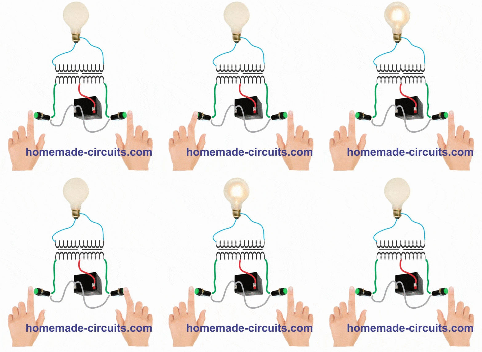
inverter operating simulation with manual switching

How the Transformer Converts a given Input

As discussed above, the transformer usually will have two winding, one primary and the other secondary.

The two winding react in such a way that a when a switching current is applied at the primary winding would cause a proportionately relevant power to be transferred across the secondary winding through electromagnetic induction.

Therefore suppose, if the primary is rated at 12V and the secondary at 220V, an oscillating or pulsating 12V DC input to the primary side would induce and generate a 220V AC across the secondary terminals.

However, the input to the primary cannot be a direct current, meaning though the source may be a DC, it must be applied in a pulsed form or intermittently across the primary, or in the form of a frequency at the specified level, we have discussed this in the previous section.

This is required so that the inherent attributes of an inductor can be implemented, according to which an inductor restricts a fluctuating current and tries to balance it by throwing an equivalent current into the system during the absence of the input pulse, also known as flyback phenomenon.

Therefore when the DC is applied, the primary stores this current, and when the DC is disconnected from the winding, allows the winding to kick back the stored current across its terminals.

However since the terminals are disconnected, this back emf gets induced into the secondary winding, constituting the required AC across the secondary output terminals.

The above explanation thus shows that a pulser circuit or more simply put, an oscillator circuit becomes imperative while designing an inverter.

Fundamental Circuit Stages of an Inverter

To build a basic functional inverter with reasonably good performance, you will need the following basic elements:

  • Transformer
  • Power Devices, such as N-channel MOSFETs or NPN Biploar Power Transistors
  • Lead Acid Battery

Block Diagram

Here's the block diagram which illustrates how to implement the above elements with a simple configuration (center tap push-pull).
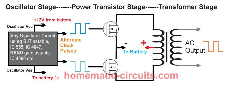
How to Design an Oscillator Circuit for an Inverter

An oscillator circuit is the crucial circuit stage in any inverter, as this stage becomes responsible for switching the Dc into the primary winding of the transformer.

An oscillator stage is perhaps the simplest part in an inverter circuit. It's basically an astable multivibrator configuration which can be made through many different ways.

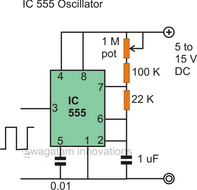
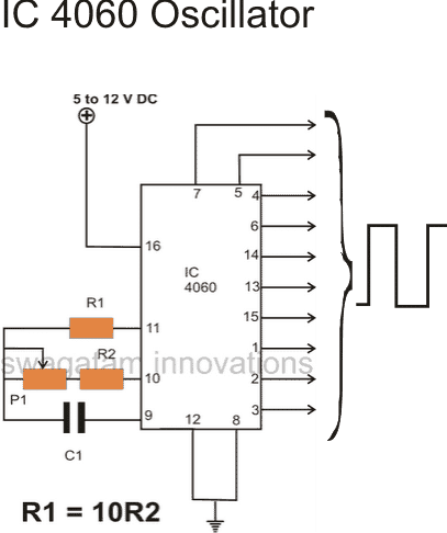
You can use NAND gates, NOR gates, devices with built-in oscillators such as IC 4060, IC LM567 or just utterly a 555 IC. Another option is the use of transistors and capacitors in standard astable mode.

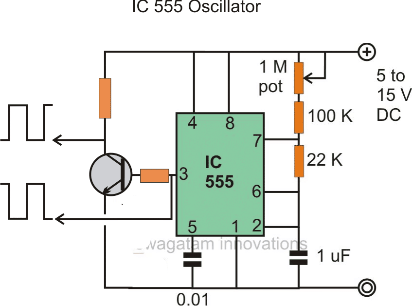
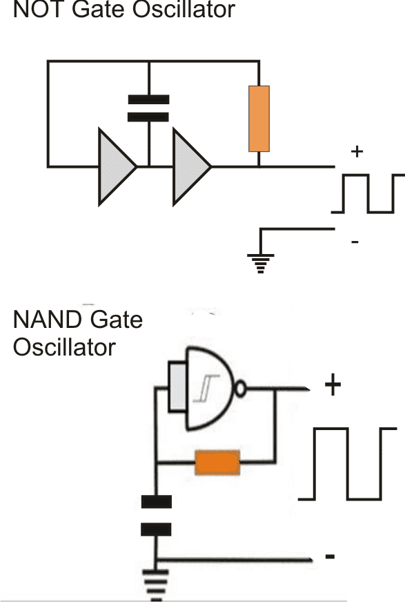
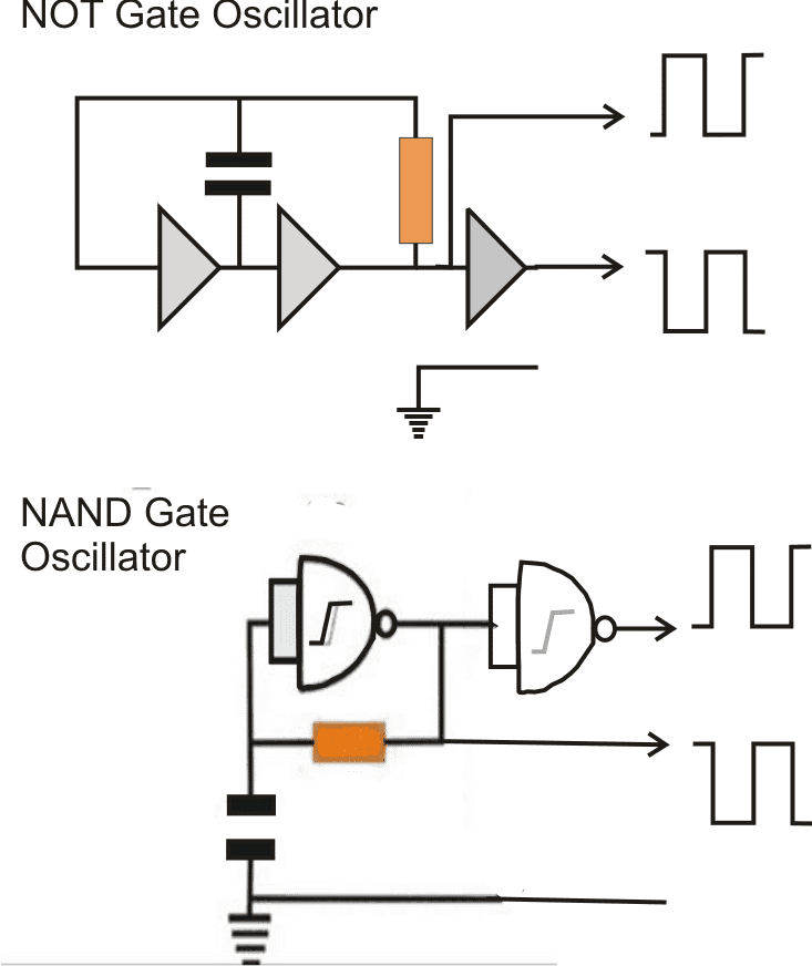
The following images show the different oscillator configurations which can be effectively employed for achieving the basic oscillations for any proposed inverter design.

In the following diagrams we see a few popular oscillator circuit designs, the outputs are square wave which are actually positive pulses, the high square blocks indicate positive potentials, the height of the square blocks indicate the voltage level, which is normally equal to the applied supply voltage to the IC, and the width of the square blocks indicate the time span for which this voltage stays alive.
The Role of an Oscillator in an Inverter Circuit

As discussed in the previous section, an oscillator stage is required for generating basic voltage pulses for feeding the subsequent power stages.

However the pulses from these stages can be too low with their current outputs, and therefore it cannot be fed directly to the transformer or to the power transistors in the output stage.

In order to push the oscillation current to the required levels, an intermediate driver stage is normally employed, which might consist of a couple of high gain medium power transistors or even something more complex.

However today with the advent of sophisticated mosfets, a driver stage may be completely eliminated.

This is because mosfets are voltage dependent devices and does not rely on current magnitudes for operating.

With the presence of a potential above 5V across their gate and source,  most mosfets would saturate and conduct fully across their drain and source, even if the current is as low as 1mA

This makes conditions hugely suitable, and easy for applying them for inverter applications.

We can see that in the above oscillator circuits, the output is a single source, however in all inverter topologies we require an alternately or oppositely polarized pulsing outputs from two sources. This can be simply achieved by adding an inverter gate stage (for inverting the voltage)  to the existing output from the oscillators, see the figures below.
Configuring Oscillator Stage to Design Small Inverter Circuits

Now let's try to understand the easy methods through which the the above explained with oscillator stages can be attached with a power stage for creating effective inverter designs quickly.

Designing an Inverter Circuit using NOT Gate Oscillator

The following figure shows how a small inverter can be configured using a NOT gate oscillator such as from the IC 4049.
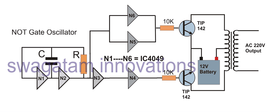
simple inverter circuit using IC 4049

Here basically N1/N2 forms the oscillator stage which create the required 50Hz or 60Hz clocks or oscillations required for the inverter operation. N3 is used for inverting these clocks because we need to apply oppositely polarized clocks for the power transformer stage.

However we can also see N4, N5 N6 gates, which are configured across the input line and output line of N3.

Actually N4, N5, N6 are simply included for accommodating the 3 extra gates available inside the IC 4049, otherwise only the first N1, N2, N3 could be alone used for the operations, without any issues.

The 3 extra gates act like buffers and also make sure that these gates are not left unconnected, which can otherwise create adverse effect on the IC in the long run.

The oppositely polarized clocks across the outputs of N4, and N5/N6 are applied to the bases of power BJT stage using TIP142 power BJTs, which are capable of handling a good 10 amp current. The transformer can be seen configured across the collectors of the BJTs.

You will find that no intermediate amplifier or driver stages are used in the above design because the TIP142 itself has an internal BJT Darlington stage for the required in-built amplification and therefore are able to comfortably amplify the low current clocks from the NOT gates into high current oscillations across the connected transformer winding.

More IC 4049 inverter designs can found below:

Homemade 2000 VA Power Inverter Circuit

Simplest Uninterrupted Power Supply (UPS) Circuit

Designing an Inverter Circuit using Schmidt Trigger NAND gate Oscillator

The following figure shows how an oscillator circuit using IC 4093 can be integrated with a similar BJT power stage for creating a useful inverter design.
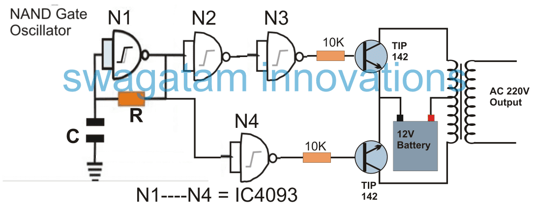
The figure demonstrates a small inverter design using IC 4093 Schmidt trigger NAND gates. Quite identically here too the N4 could have been avoided and the BJT bases could have been directly connected across the inputs and the outputs N3. But again, N4 is included to accommodate the one extra gate inside the IC 4093 and to ensure that its input pin not left unconnected.

More similar IC 4093 Inverter designs can be referred from the following links:

Best Modified Inverter Circuits

How to Make a Solar Inverter Circuit

How to Build a 400 Watt High Power Inverter Circuit with Built in Charger

How to Design an UPS Circuit – Tutorial

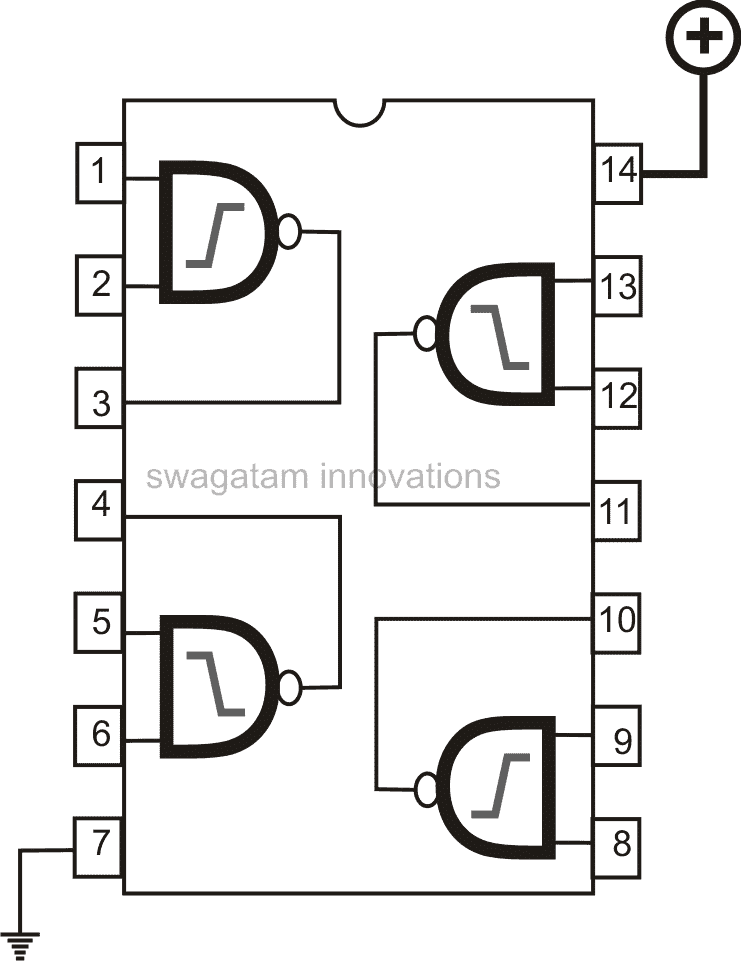
Pinout diagrams for the IC 4093 and IC 4049
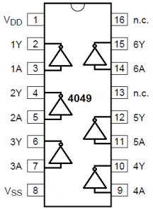
NOTE: The Vcc, and Vss supply pins of the IC are not shown in the inverter diagrams, these must be appropriately connected with the 12V battery supply, for 12V inverters. For higher voltage inverters this supply must be appropriately stepped down to 12V for the IC supply pins.

Designing a Mini Inverter Circuit using IC 555 Oscillator

From the above examples, it becomes quite evident that the most basic forms of inverters could be designed by simply coupling a BJT + transformer power stage with an oscillator stage.

Following the same principle an IC 555 oscillator can be also used for designing a small inverter as shown below:
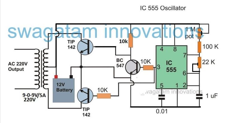
The above circuit is self explanatory, and perhaps does not require any further explanation.

More such IC 555 inverter circuit can be found below:

Simple IC 555 Inverter Circuit

Understanding Inverter Topologies (How to Configure the Output Stage)

In the above sections I have explained about the oscillator stages, and also the fact that the pulsed voltage from the oscillator goes straight to the preceding power output stage.

There are primarily three ways through which an output stage of an inverter may be designed.

By Using a:

  1. Push Pull Stage (with Center Tap Transformer) as explained in the above examples
  2. Push Pull Half-Bridge Stage
  3. Push Pull Full-Bridge or H-Bridge Stage

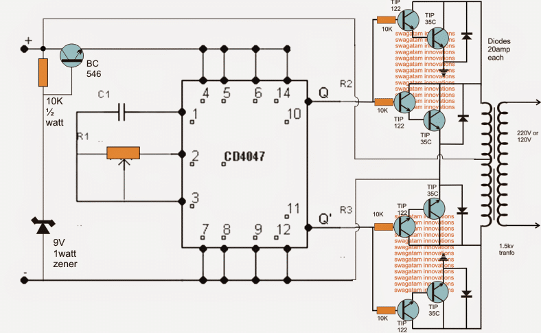
The push pull stage using a center tap transformer is the most popular design because it involves simpler implementations and produces guaranteed results.

However it requires bulkier transformers and output is lower in efficiency.

A couple of inverter designs can be seen below which employs a center tap transformer:
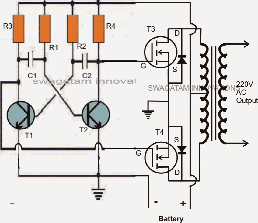
In this configuration, basically a center-tap transformer is used with its outer taps connected to the hot ends of the output devices (transistors or mosfets) while the center tap either goes to the negative of the battery or to the positive of the battery depending upon the type of devices used (N type or P type).

Half-Bridge Topology

A half bridge stage does not make use of a center tap transformer.

A half bridge configuration is better than a center tap push pull type of circuit in terms of compactness and efficiency, however it requires large value capacitors for implementing the above functions.
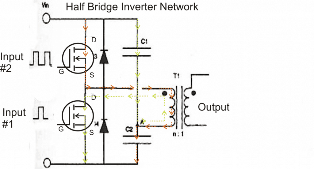
A full bridge or an H-bridge inverter is similar to a half bridge network since it also incorporates an ordinary two tap transformer and does not require a center tap transformer.

The only difference being the elimination of the capacitors and the inclusion of two more power devices.

Full-Bridge Topology

A full bridge inverter circuit consists of four transistors or mosfets arranged in a configuration resembling the letter "H".

All the four devices may be N channel type or with two N channel and two P channel depending upon the external driver oscillator stage that's being used.

Just like a half bridge, a full bridge also requires separate, isolated alternately oscillating outputs for triggering the devices.

The result is the same, the connected transformer primary is subjected to a reverse forward kind of switching of the battery current through it. This generates the required induced stepped up voltage across the output secondary winding of the transformer. Efficiency is highest with this design.

H-Bridge Transistor Logic Details

The following diagram shows a typical H-bridge configuration, the switching are made as under:

  1. A HIGH, D HIGH - forward push
  2. B HIGH, C HIGH - reverse pull
  3. A HIGH, B HIGH - dangerous (prohibited)
  4. C HIGH, D HIGH - dangerous (prohibited)
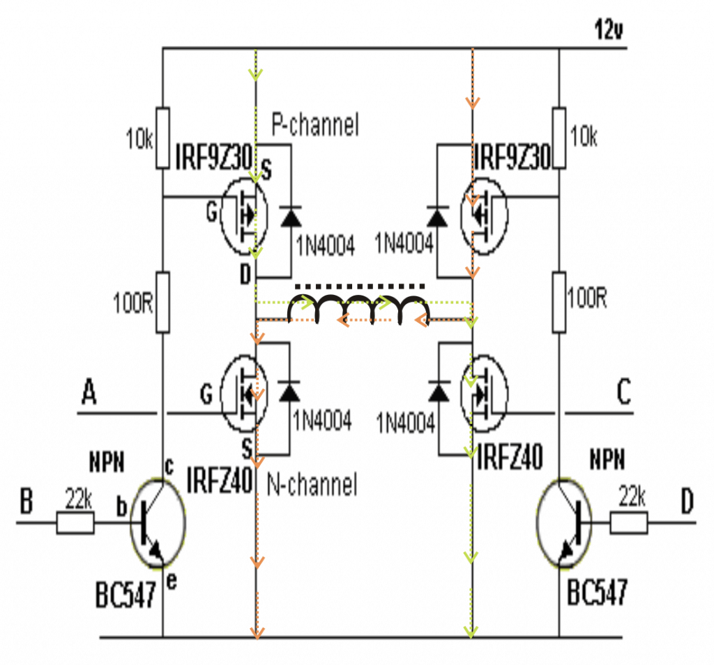
The above explanation provides the basic information regarding how to design an inverter, and may be incorporated only for designing a ordinary inverter circuits, typically the square wave types.

However there are many further concepts that may be associated with inverter designs like making a sine wave inverter, PWM based inverter, output controlled inverter, these are just additional stages which may be added in the above explained basic designs for implementing the said functions.

We will discuss them some other time or may be through your valuable comments.

You'll also like:

  • SYNCEDINVERTERSynchronized 4kva Stackable Inverter
  • automatic2Bbattery2Bcharger2BcircuitGenerator/UPS/Battery Relay Changeover Circuit
  • inverterHow an Inverter Functions, How to Repair Inverters – General Tips
  • IR2111 H-Bridge Inverter Circuit with Soft Start

Filed Under: Inverter Circuits Tagged With: Design, Inverter, Theory, Tutorial

About Swagatam

I am an electronics engineer and doing practical hands-on work from more than 15 years now. Building real circuits, testing them and also making PCB layouts by myself. I really love doing all these things like inventing something new, designing electronics and also helping other people like hobby guys who want to make their own cool circuits at home.

And that is the main reason why I started this website homemade-circuits.com, to share different types of circuit ideas..

If you are having any kind of doubt or question related to circuits then just write down your question in the comment box below, I am like always checking, so I guarantee I will reply you for sure!


Previous Post: « 12V DC to 220V DC Boost Converter Circuit
Next Post: 3 Interesting DRL (Day Time Running Light) Circuits for Your Car »

Reader Interactions

Questions & Answers

Total Posts: 155
Newest Oldest
Pulakesh Kumar KALITA
July 21, 2024 • 2 years ago #155609

Commendable article. Impressively designed and narrated

Reply
SwagatamAdmin
July 22, 2024 • 2 years ago #155653

Thank you! Glad you found it useful.

Reply
DLF
May 8, 2024 • 2 years ago #152084

There is an engineering-level series on inverter design optimization in the newsletter at how2power.com It has 23 parts and has been running for over a year, with inverter design articles in nearly every issue.

Reply
fadhili
January 22, 2024 • 3 years ago #148699

OK, thanks, nice to talk to you, by the way, i’m from Tanzania, nice to meet you, thanks for replying my question 

Reply
SwagatamAdmin
January 22, 2024 • 3 years ago #148701

You are welcome fadhili…

Reply
Dwi Agus Setiawan
May 25, 2023 • 3 years ago #142853

hi dude, is a JT also classified as inverter..??? i was really wonder about JT, i’ve build ones to drive a 15W LED lamp (normally it’s 220Vac supply)…

i was sukses driving this 15w led using a JT (using 12v dry cell as supply) but the Transistor (C5192) was very hot… have any idea to cool it down without using fan..???

Reply
SwagatamAdmin
May 25, 2023 • 3 years ago #142855

Sorry, I have never heard of JT, so not sure what exactly it is and how it may be related to an inverter? You can keep the transistor cool by replacing the transistor with higher rated one and by attaching a large heatsink to it. You can try using a TIP122 transistor

Reply
Dwi Agus Setiawan
May 25, 2023 • 3 years ago #142856

really don’t know about JT, Joule-thief, a simple blocking oscillators.. just type “JT” in google search box and you ‘ll find the result

Reply
SwagatamAdmin
May 25, 2023 • 3 years ago #142858

NO, searching JT in Google does not produce the result Joule-thief.
You could have simply mentioned Joule-thief instead of writing JT.

Reply
Dwi Agus Setiawan
May 25, 2023 • 3 years ago #142860

ooopppsss… OK dude, it’s my bad…. bact to the main question, is Joule-Thief classified as an inverter too.. and how to make the transistor cooler, instead having a bulky heatsink nor using fan, i’m install it in my motorcycle as a lighting, so the bulk heat-sink is the problem it self…

Reply
SwagatamAdmin
May 25, 2023 • 3 years ago #142862

Joule Thief is not an inverter. It is a simple voltage booster or step-up converter circuit that can efficiently drive a load using a low-voltage power source, such as a single-cell battery. The primary purpose of the Joule Thief is to extract the remaining energy from a nearly depleted battery that would otherwise be considered unusable.
You can try a bigger transistor such as a TIP35, if it still heats up then there’s no other alternative but to use a heatsink.

Reply
Dwi Agus Setiawan
May 25, 2023 • 3 years ago #142866

thank’s dude, i was done attached a heatsink in my circuit at first, the transistor gone heated-up ’cause i decrease the bias resistor, when i use 1K the transistor stay cool (Vout = 97Vdc), but the light seem too dim… then i decrease the R to 330 ohm, the light seems brighter (Vout = 125Vdc) but the Tr goes to heat,..this is the problem,..

i was wonder how the ideal value for Rb and the ideal Np/Nf for the inductor,.. may with the ideal value for both the led still bright, but the transistor stay cool…

NB :
Np = Turn of Primary winding
Nf = Turn of Feedback winding
Rb = value of Bias Resistor

Reply
SwagatamAdmin
May 25, 2023 • 3 years ago #142867

The transistor is getting hot because it is being driven with overload and over current. I have suggested you the transistor number in my previous comment, you can use that to keep the transistor cooler.

Reply
Dwi Agus Setiawan
May 25, 2023 • 3 years ago #142869

OK, thanks man, nice to talk to you, by the way, i’m from indonesian, nice to meet you, thanks for replying my question,

Reply
SwagatamAdmin
May 25, 2023 • 3 years ago #142871

No problem Dwi, Glad to talk to you. Let me know if you have more questions.

Reply
krishna
May 18, 2023 • 3 years ago #142661

What is the best material that can be used for the outer casing of the invertor

Reply
SwagatamAdmin
May 18, 2023 • 3 years ago #142663

Aluminum.

Reply
Nitron Adewale
October 31, 2022 • 4 years ago #134234

A group of us, in a third world country Nigeria, got together, bought components and had a technician put it together to give a 3.5kva inverter that functions perfectly.
We now wish to incorporate a remote monitoring and control system to be able to remotely switch on and off as well as monitor data from the system so as to ensure optimal operation at all times.
Neither we the owners, nor our technician knows how to go about it.
Kindly assist.

Reply
SwagatamAdmin
November 1, 2022 • 4 years ago #134250

Hello, that might require too many complex circuits and networks, moreover the range will not be more than 50 meters.

Reply
Kemba Rene
September 15, 2022 • 4 years ago #133258

How do I repair an inverter with output short-circuited?

Reply
SwagatamAdmin
September 15, 2022 • 4 years ago #133260

If the output was shorted then probably the mosfets are blown….you will have to check the mosfets

Reply
Mark
May 24, 2022 • 4 years ago #121766

How do i repair an inverter which will not power on but the fuse and power button are good

Reply
SwagatamAdmin
May 25, 2022 • 4 years ago #121892

You must check whether the output wires are broken or not or whether the inverter is switching ON or not using the battery power.

Reply
Adelani Olanrewaju Israel
March 19, 2022 • 4 years ago #116545

Hi, thanks for coming up with this site, it has helped me alot in some projects.

Please I am trying to build 1kva inverter, can you guild me please?

Thanks

Reply
SwagatamAdmin
March 20, 2022 • 4 years ago #116658

Hi, 1 kva inverter will require a 36V or 48V battery….you can refer to the following design, and try building it:

1500 watt PWM Sinewave Inverter Circuit

Reply
Aliyu Danjuma Egga
January 18, 2022 • 5 years ago #109983

Hello sir, am a hobbyist and also a student in this descipline sir, I wanted to build an inverter using an old 2000watts stabilizer transformer core, I have been watching some YouTube videos on how to obtain the required parameters needed like TPV, SWG and Number of MOSFET to use supposed I want to build a 1kva inverter.
Please sir how do get all that from the transformer core size or Bobbin core area? Looking forward to your response sir thank you

Reply
SwagatamAdmin
January 18, 2022 • 5 years ago #109994

Hello Aliyu, you will need a center tap transformer such as 12-0-12V or 9-0-9V, for a 12V powered inverter. You will have to check the existing transformer whether such a winding is available or not. If it is available then you can use it for making an inverter.

Reply
Nimel
August 23, 2021 • 5 years ago #95284

Pls sir, what kind of oscillator stage is used with either full or half bridge

Reply
SwagatamAdmin
August 23, 2021 • 5 years ago #95306

Square wave and sine wave oscillators are used for making all types inverters.

Reply
Nimel
August 22, 2021 • 5 years ago #95266

Thanks for a wonderful explanation here

Reply
SwagatamAdmin
August 22, 2021 • 5 years ago #95267

Thanks, glad you liked it!

Reply
Evan
June 14, 2021 • 5 years ago #90964

I once drove an inductive load with an inverter. Turning off the load broke the inverter. However, I cannot find where the circuit failed. Where would you expect an inverter to fail under an inductive load?

Reply
SwagatamAdmin
June 14, 2021 • 5 years ago #90975

Mostly it could be the power devices (MOSFETs, IGBTs) that might have burned, so you can isolate the power devices from the main circuit and check if they are OK or blown.

Reply
Shankar Singh
May 17, 2021 • 5 years ago #89686

Good day sir, please I have this smiley su-kam 1.4KVa inverter showing high voltage output @ 280v. Even on load the voltage is still 280v. It’s burned about 3 incandescent bulbs already, I tried varying the two potentiometer on the PCB, no change was noticed, I even went ahead to change the PT but all still the same. What is the possible cause and solution to it sir. Thanks.

Reply
SwagatamAdmin
May 17, 2021 • 5 years ago #89696

Hi Shankar, it seems the feedback control system is not working correctly, or malfunctioning. You will have to identify how the feedback system is configured from the AC output to one of the the IC input pins, and then troubleshoot why this feedback is not working for the output voltage correction

Reply
Ahmed Nii Aryeetey
September 8, 2020 • 6 years ago #82091

Hello please am new to electronics and i want to build, a pure sine wave inverter, any help from anybody here please.
thank you

Reply
Eben
July 22, 2020 • 6 years ago #80620

Thank you sir for your impact.

Please sir I need 1000watt inverter circuit

Reply
SwagatamAdmin
July 22, 2020 • 6 years ago #80627

Eben, you can try the following one

500 Watt Inverter Circuit with Battery Charger:

Use two MOSFETs in parallel on each channel

Battery must be 500 Ah minimum

Reply
Eben
July 19, 2020 • 6 years ago #80547

I really appreciate your effort sir for the kin knowledge.
I build an inverter using SG3524 in the oscillator stage and 8 IRF3205 With a 12-0-12 transformer that is a 24v transformer after building the circuit it was giving me an output voltage of 175v but when I connect a load of 60watt the voltage begins to countdown. Am using a 12v battery of should I connect two 12v in series to power the circuit.

Reply
SwagatamAdmin
July 20, 2020 • 6 years ago #80558

Please provide the wattage of the transformer and Ah value of the battery?

Reply
Eben
July 21, 2020 • 6 years ago #80595

1000watt transformer with an input voltage of 220v and output of 24v then the battery is just 72Ah.

Reply
SwagatamAdmin
July 21, 2020 • 6 years ago #80604

The power rating are quite substantial so 60 watt load shouldn’t have caused any drop. The transformer primary voltage should be slightly less than the battery voltage, so make sure this is also followed.

Reply
Eben
July 21, 2020 • 6 years ago #80607

Sir what of if I connect two 12v battery in series to get 24v will the circuit work fine.

Reply
Eben
July 22, 2020 • 6 years ago #80634

What can I do to remedy the voltage drop

Reply
SwagatamAdmin
July 23, 2020 • 6 years ago #80643

Your inverter has problems, so you must troubleshoot them, that’s the only remedy…
your transformer, battery, are oK…verify the MOSFeTs and the frequency of the oscillator

Reply
SwagatamAdmin
July 22, 2020 • 6 years ago #80623

Whether it is a single 24V or two 12 in series, the effect will be the same.

Reply
faith jumbo
July 13, 2020 • 6 years ago #80318

I must commend you for your efforts may God continue to bless you, sir I have question
In modified or sine wave inverter the transformer voltage is always equal to voltage at gate of the MOSFET i.e if the inverter is 12v the transformer voltage is 7v and for 24v it’s 14v my question is this how do this voltage charge a battery because to charge a 12v battery we need at least 14v and this inverter use the same transformer for both inverting and charging, how will this 7v at the transformer be increased to 14v and charge a battery
Thanks and best regards

Reply
SwagatamAdmin
July 13, 2020 • 6 years ago #80321

The same transformer cannot be used for charging the battery. You will have to employ a separate transformer or a separate winding in the main transformer

Reply
Oluwashina
July 8, 2020 • 6 years ago #80198

Hello sir
How can I make a circuit for my 12v 0 12v 150ah inverter transformer

Reply
Emmy E
May 22, 2020 • 6 years ago #78920

Hello Sir. I appreciate you for your wonderful and immense technical know how you been giving to the world. May God reward you for not with holding your knowledge.
Please sir, I want to ask a question and I wish there is a way to attach a file for clarity sake.
Nevertheless, why is the terminals (+ -) of a Battery UPS (Blue Gate 2kva) connected to the heatsink of the Mosfets instead of the terminals of the Mosfets?
Again can you help reproduce the schematic diagram of the above mentioned.

Reply
SwagatamAdmin
May 23, 2020 • 6 years ago #78928

Thank you Emmy, +/- both connected with the heatsink sounds strange. The tab of a MOSFET is normally kept isolated from any connections. it can be difficult to judge the situation in your UPS unless we know the specifications of the MOSFET used.

Reply
ssm
May 6, 2020 • 6 years ago #78461

Hello sir,
Your work always inspire me and allows me to think out of the way.
Sir I need your help, as I am designing DC-AC inverter, but the the DC voltage is 3 – 4.2 vDC as I am using li-ion 3.7 v battery to get 60vAC at the output. Also I am using solar panel for battery to charge.
I do referred the about circuit and tried, but I am not able to get the required output.
Please refer the modification from the about circuit that I should consider while designing circuit.
Thank you.

Reply
SwagatamAdmin
May 6, 2020 • 6 years ago #78484

Thanks SSM, to make a 3.7 /60 V inverter, you will first need a 3-0-3V/60 transformer, do you have that??

Reply
ssm
May 12, 2020 • 6 years ago #78646

No sir I was not able to find the 3-0-3v/60 transformer.
So what else are the options that I can use.
Is it possible to design the inverter without transformer?
Thank you for the help.

Reply
SwagatamAdmin
May 12, 2020 • 6 years ago #78657

For transformerless inverter you will need a 84 v DC supply which will be then converted to 60 V AC through a full bridge inverter circuit

Reply
ssm
May 8, 2020 • 6 years ago #78535

I tried finding online, but was not able to found one. Is there any other way you can suggest me that will help me in designing the inverter.
thank you for the reply.

Reply
SwagatamAdmin
May 8, 2020 • 6 years ago #78540

You may also try the following article:

https://www.homemade-circuits.com/7-simple-inverter-circuits/

Reply
Jan
February 24, 2020 • 6 years ago #76893

Hi Swagatam,
1)On your Mini Inverter using IC 555 Circuit. There is a resistor from Pin 4 & 8 on the IC going to BC547 collector and then to Pin 3 on the IC. Please give me the value of the resistor.
2) Also, I think that Pin 4 & 8 must be connected to +12V.
3) I would prefer to use TIP3055 instead of TIP142. Is this possible?
Your assistance will be much appreciated.
Regards
Jan

Reply
SwagatamAdmin
February 25, 2020 • 6 years ago #76902

Hi Jan, I have joined the pin4/8 with the positive and have updated a new diagram for your reference.

You can use TIP3055 but you will have to connect another BJT with it to create a Darlington pair. The other BJT can be a 2N2222 transistor

Reply
Jan
February 25, 2020 • 6 years ago #76906

Thank you Swagatam.
Much appreciated
Regards
Jan

Reply
SwagatamAdmin
February 25, 2020 • 6 years ago #76907

You are welcome Jan!

Reply
Dewise
February 14, 2020 • 7 years ago #76521

Good day sir, please I want to know how to determine the numbers of drivers to be used for any inverter circuit. thanks

Reply
SwagatamAdmin
February 14, 2020 • 7 years ago #76541

Hello Dewise, I did not understand your question correctly…

Reply
Muzamil
September 23, 2019 • 7 years ago #70436

Hi..!!
Sir i need inverter(dc to ac) designing and its circuit diagram.

Reply
EBUKA
July 30, 2019 • 7 years ago #68862

HELLO SIR I NEED A GUIDE ON HOW TO BUILD AN INVERTER CIRCUIT WITH REMOTE CONTROL

Reply
SwagatamAdmin
July 30, 2019 • 7 years ago #68866

Hello Ebuka, you can use remote controlled rely to control the battery supply of any inverter. The remote circuit is given below:

https://www.homemade-circuits.com/simple-100-meter-rf-module-remote/

Reply
TONY
July 9, 2019 • 7 years ago #68305

Hello sir, thanks for your good work in impact knowledge to many ,specially me in particular. I am a student of Electronic Engineering currently work on a project to design a DC-DC inverter , DC-AC inverter for solar energy Grid connected system,Please, i need your input and technical diagram will be valued.

Reply
SwagatamAdmin
July 9, 2019 • 7 years ago #68307

Thank you Tony, I have many DC-AC, and DC-DC inverter circuits and a few GTI concepts which you can find through the search box above. Once you find a suitable one then I can guide you further with it.

Reply
SH. A
November 11, 2022 • 4 years ago #134612

please, i want the equation which using for design inverter

Reply
Abiola Babatunde
June 16, 2019 • 7 years ago #67695

I am interested in electronics and I don’t have any prior knowledge of it. I want your tutelage and guidance.
I am 50 years and want to revolutionize the power system in my country, Nigeria with solar inverter.
Hope you will be of good assistance.
Thank you.

Reply
SwagatamAdmin
June 16, 2019 • 7 years ago #67708

I wish you all the best, let me know if you have specific questions, I’ll try to help!

Reply
Andu
January 17, 2020 • 7 years ago #74815

Thank you so much sir for your great work but i want to build pure sine wave inverter please add other necessary stage in this tutorial
Thanks…

Reply
SwagatamAdmin
January 17, 2020 • 7 years ago #74880

No problem Andu, you can refer to the following page

https://www.homemade-circuits.com/?s=pure+sinewave

Reply
Eniola Sodiq
April 23, 2019 • 7 years ago #66620

Thanks for always being there, Sir
Yesterday, I tested my inverter with a 12V 100AH battery, and immediately I pressed the switch, the wire heated up and even gave small sparks. I don’t understand the cause sir, please help.

Reply
SwagatamAdmin
April 23, 2019 • 7 years ago #66621

Hi Eniola, which inverter design have you used, please show me the schematic? There’s certainly some problem with the oscillator or the power devices in your inverter,
connect a 12V 5 amp bulb in series with the battery positive, and troubleshoot the fault until the bulb stops illuminating with full power. Full illumination will indicate some serious problem or short circuit in your circuit.

Reply
Eniola Sodiq
April 20, 2019 • 7 years ago #66572

Hi Swagatam Sir
I’ve been able to build the inverter following the circuit diagram you sent me.
But it is giving an output voltage of 54 volts, what can be the problem?? Can this be due to my transformer because I used a small 2A transformer to test it.

Reply
SwagatamAdmin
April 21, 2019 • 7 years ago #66579

Hi Eniola, Is it without any load? In that case the transformer is the culprit, if it’s with load then the load may be more than 12 x 2 = 24 watts, because a 12V 2 amp trafo will produce less than 24 watts so anything higher than 20 watts will drop the output voltage drastically.

Reply
Eniola Sodiq
April 19, 2019 • 7 years ago #66552

Hi Swagatam, Sir
What will be the output of the inverter if I use
(a) 8 IRF540N MOSFETS
(b) 6 IRFP250 MOSFETS

and which one will you prefer for a high power output?

Reply
SwagatamAdmin
April 19, 2019 • 7 years ago #66557

Hi Eniola, mosfets are only switches, the maximum handling power of the mosfet depends on its drain/source current rating (Id), add the Id rating off all parallel mosfets, that will be the maximum handling power of the msofets. The actual power comes from the battery

Reply
Eniola Sodiq
April 15, 2019 • 7 years ago #66495

Hi, dear Swagatam Sir
I need your help on battery charger design.
Is it necessary I use a voltage regulator such as LM7812 in the design of a 12V charger?
Can you send me the best battery charger circuit for a 12V, 150AH battery? What’s the best ampere rating for such a charger?

Reply
SwagatamAdmin
April 16, 2019 • 7 years ago #66499

Hi Eniola, for a 150Ah battery the charging voltage will need to be 14V and the current around 15 to 20 amps. 7812 will not be required here.

you can try the following link:

https://www.homemade-circuits.com/opamp-low-high-battery-charger/

Reply
Eniola Sodiq
March 23, 2019 • 7 years ago #66030

Hi, Swagatam Sir.
1. What is the right resistors and capacitors to be used with CD4047 and IRFP250N?
2. Can you give a detailed explanation (or link) to how to determine the right capacitors to be used in a circuit?

Reply
SwagatamAdmin
March 23, 2019 • 7 years ago #66033

Hi Eniola,
4047 requires just a single resistor and capacitor. The resistor can be a 1/4 watt and capacitor can be an ordinary ceramic disc type. The values will depend on the required frequency output which can be solved either with trial and error or through the specified formula.
Capacitors are fundamentally charge storing and time delay determining components. So depending on the application this time interval can be calculated with formulas, and the charge/discharge function can be determined based on the capacitor’s uF value. Capacitors are also used for blocking DC and allowing AC

Some information can be read here:

https://www.homemade-circuits.com/understanding-capacitors-made-easy/

Reply
Eniola Sodiq
March 19, 2019 • 7 years ago #65960

Good day.
Can you please send me two or three circuit diagrams for 1000watts inverter circuits.
Also, can I change MOSFETS for higher output?

Reply
SwagatamAdmin
March 19, 2019 • 7 years ago #65961

Eniola, you can use any simple inverter circuit and convert it into a 1000 watt inverter simply by upgrading its transistors and tramsformer. Here’s the details

https://www.homemade-circuits.com/upgrading-low-power-inverter-to-high/

Reply
Eniola Sodiq
March 15, 2019 • 7 years ago #65890

Hi Sir. You are really doing a great job.
Please, a friend’s inverter is faulty. The inverter got burnt, it’s still working but it’s smelling and vibrating. What’s the possible problems and solutions sir. Thanks

Reply
SwagatamAdmin
March 15, 2019 • 7 years ago #65891

Thanks Eniola, If it’s working yet smelling and vibrating then most probably it’s the transformer that’s short circuited and getting burnt. Try changing the transformer and check the response!

Reply
Omar
October 12, 2017 • 9 years ago #54752

Hi, about the Half-Bridge, kindly i need to know what type of capacitors? and how much value should be?

Reply
SwagatamAdmin
October 13, 2017 • 9 years ago #54758

Hi, you can use any capacitor above 1000uF…

Reply
SwagatamAdmin
November 6, 2016 • 10 years ago #46202

by doing normal soldering procedures

Reply
Paritosh Hanspal
March 18, 2016 • 10 years ago #39820

its working awesome sir.. just completed the circuitry..thanx alot.. hope someday i may be able to follow your footmarks.. i am damn passionate for electrical & electronics both..
so each n every words from you i read every article.. the way u explain to some NOOBs!!! thumbs up..!
keep up the good work sir.. coz some1 here idolizes u..!
good day sir!

Reply
SwagatamAdmin
March 18, 2016 • 10 years ago #39826

That's great Paritosh,congrats to you. definitely you will be able to reach your goals very soon, just keep working hard, and feel free to comment and ask your queries here whenever you are stuck….

Reply
Paritosh Hanspal
March 17, 2016 • 10 years ago #39789

sir i am tired of mosfets blowing away.. got a centretapped trafo. from old frontech ups.
cd4047 with 2 irfz44 cant bear the load.. so shall i connect same mosfets in parallel or should i try anything else.. lyk irf540 or switching to 2n3055 circuit explained by you with 4049..

efficiency wise…!

Reply
SwagatamAdmin
March 18, 2016 • 10 years ago #39804

Paritosh, you can try TIP142 BJT instead, and see how it performs.
2N3055 can also be tried but for that the IC 555's BC547 will need to be replaced with 2N2222, and its collector resistor with a 100 ohm 5 watt resistor

Reply
Paritosh Hanspal
March 15, 2016 • 10 years ago #39705

thanx for your guidance sir.. its an honor for me..!
gonna build the above & 2nd last circuit & inform u as soon it works,,!!!
have a nice day.

Reply
SwagatamAdmin
March 16, 2016 • 10 years ago #39727

you are welcome Paritosh.

Reply
View Older Comments

Need Help? Please Leave a Comment! We value your input—Kindly keep it relevant to the above topic! Cancel reply

Your email address will not be published. Required fields are marked *

Primary Sidebar


Categories

  • Arduino Projects (95)
  • Audio and Amplifier Projects (134)
  • Automation Projects (18)
  • Automobile Electronics (104)
  • Battery Charger Circuits (90)
  • Datasheets and Components (109)
  • Electronics Theory (150)
  • Energy from Magnets and Earth (41)
  • Games and Sports Projects (11)
  • Grid and 3-Phase (20)
  • Health related Projects (27)
  • Home Electrical Circuits (13)
  • Indicator Circuits (16)
  • Inverter Circuits (100)
  • Lamps and Lights (163)
  • Meters and Testers (72)
  • Mini Projects (28)
  • Motor Controller (68)
  • Oscillator Circuits (30)
  • Pets and Pests (15)
  • Power Supply Circuits (91)
  • Remote Control Circuits (50)
  • Security and Alarm (65)
  • Sensors and Detectors (107)
  • SMPS and Converters (46)
  • Solar Controller Circuits (62)
  • Temperature Controllers (44)
  • Timer and Delay Relay (50)
  • Voltage Control and Protection (44)
  • Water Controller (37)
  • Wireless Circuits (31)


Circuit Simulator

circuit simulator image


Subscribe to get New Circuits in your Email


Other Links

  • Privacy Policy
  • Cookie Policy
  • Disclaimer
  • Copyright
  • Videos
  • Sitemap

People also Search

555 Circuits | 741 Circuits | LM324 Circuits | LM338 Circuits | 4017 Circuits | Ultrasonic Projects | SMPS Projects | Christmas Projects | MOSFETs | Radio Circuits | Laser Circuits | PIR Projects |


Recent Comments

  • Swagatam on Electronic Circuit Projects, Tutorials, and Practical Engineering Solutions
  • Swagatam on 50 Watt Sine Wave UPS Circuit
  • Tom Sendelbeck on Electronic Circuit Projects, Tutorials, and Practical Engineering Solutions
  • Alireza.Moghaddam on 50 Watt Sine Wave UPS Circuit
  • Swagatam on Simple Walkie Talkie Circuit

Social Profiles

  • Twitter
  • YouTube
  • Instagram
  • Pinterest
  • My Facebook-Page
  • Stack Exchange
  • Linkedin

© 2026 · Swagatam Innovations