The circuit provided in this article shows you a simple way of building a useful liitle inverter that's easy to build and yet provides the features of a pure sine wave inverter. The circuit can be easily modified for getting higher outputs.
Introduction
Let’s begin the discussion about how to build a 120 Volt, 100 watt sine wave inverter, by first learning it’s circuit functioning details:
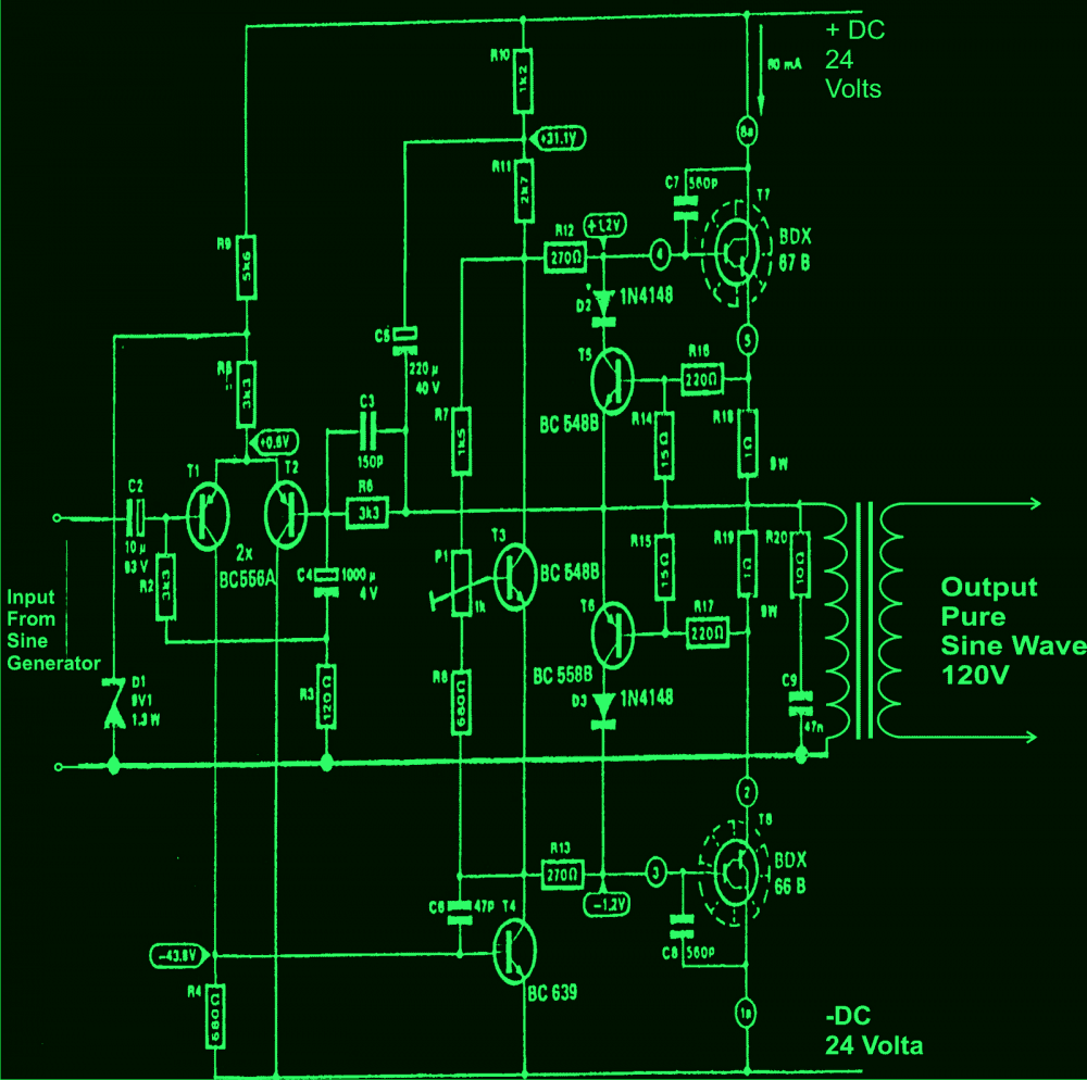
The circuit can be basically divided in to two stages viz: the oscillator stage and the power output stage.
Oscillator Stage:
Please refer the detailed explanation about this stage in this pure sine wave article.
The power output stage:
Looking at the circuit diagram we can see that the entire configuration is fundamentally made up of three sections.
The input stage consisting of T1 and T2 form a discrete differential amplifier, responsible for boosting the low amplitude input signal from the sine generator.
The driver stage consists of T4 as the main component whose collector is connected to the emitter of T3.
The configuration quite replicates an adjustable zener diode and is used for settling the quiescent current of the circuit.
A full fledged output stage comprising Darlington transistors T7 and T8 forms the final stage of the circuit after the driver stage.
The above three stages are integrated with each other to form a perfect high power sine wave inverter circuit.
The best feature of the circuit is its high input impedance, around 100K which helps to keep the input sine waveform shape intact and distortion free.
The design is pretty straightforward and will not pose any problems if built correctly as per the circuit diagram and the provided instructions.
Battery Power
As we all know that the biggest drawback with sine wave inverters is its RED HOT output devices, which drastically reduces the over all efficiency of the system.
This can be avoided by increasing the input battery voltage up to the maximum possible tolerable limits of the devices.
This will help to reduce the current requirements of the circuit and thus help to keep the devices cooler. The approach will also help to increase the efficiency of the system.
Here, the voltage can be increased up to 48 volts plus/minus by connecting eight small sized 12 volt batteries in series as shown in the figure.
The batteries can be 12 V, 7 AH type each and may be tied in series for getting the required supply for the inverter circuit.
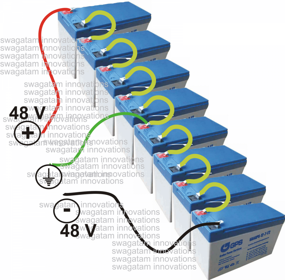
The TRANSFORMER is a made to order type, with an input winding of 48 – 0 – 48 V, 3 Amps, output is 120V, 1 Amp.
Once this is done, you can rest assured of a clean, hassle free pure sine wave output that may be used for powering ANY electrical gadget, even your computer.
Adjusting the Preset
The preset P1 may be used to optimize the sine waveform at the output and also to increase the output power to optimal levels.
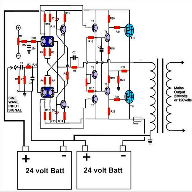
Another power output stage is shown below using MOSFETs, which may be used in conjunction with the above discussed sine generator circuit for making a 150 watts high power pure sine wave inverter.
Parts List
- R1 = 100K
- R2 = 100K
- R3 = 2K
- R4,5,6,7 = 33 E
- R8 = 3K3,
- R9 = 1K PRESET,
- R10,11,12,13 = 1K2,
- R14,15 = 470E,
- R16 = 3K3,
- R17 = 470E,
- R18,19,21,24 = 12E,
- R22 = 220, 5 WATT
- R20,25 = 220E,
- R23 = 56E, 5 WATTS
- R26 = 5E6, ½ WATT
- C1 = 2.2uF, PPC,
- C2 = 1n,
- C3 = 330pF,
- C6 = 0.1uF, mkt,
- T1 = BC547B 2nos. matched pair
- T2 = BC557B 2nos. matched pair
- T3 = BC557B,
- T4 = BC547B,
- T7,9 = TIP32,
- T5,6,8 = TIP31,
- T10 = IRF9540,
- T11 = IRF540,
- Oscillator Parts List
- R1 = 14K3 (12K1),
- R2, R3, R4, R7, R8 = 1K,
- R5, R6 = 2K2 (1K9),
- R9 = 20K
- C1, C2 = 1µF, TANT.
- C3 = 2µF, TANT (TWO 1µF IN PARALLEL)
- IC = 324

Questions & Answers
Am suffering from the software to use ,using multisim to find components is very difficult for me now ,that my biggest problem.
returned to your site using a several years old lm555 image search of schematic. didn’t quite understand the PWM part but 1980’s physical prototype revealed a MM5369 60hz crystal time base actually doubled the frequency, using signal and buffer into low power push pull type transformer. It would have required dividing the frequency to 30hz.
Ing. 1- Could you help me with a pure sine wave inverter circuit with the ci: 4047
2- Some circuit with the ci: 4047 to use in home appliances ceiling fan..tv, Pc-notebook
3- In the case of inverter circuit with 4047 square wave which devices would be used and which would not
You can try the following circuit:
Pure Sine Wave Inverter Circuit Using IC 4047
you can use all types of appliances with the above circuit.
Please sir, how can I made 100w/220V pure sine wave inverter with 12V battery
Hi, your circuit for the 150W pure sine wave inverter using mosfets has a few errors hope you can rectify;
1/ There is a resistor joining the base of T3 and base of T4, looks like ‘R5’ but there is already another R5, what value should it be?
2/ There are two C2s on the circuit, which one is 1nF, what is the value of the other?
3/ There is a C6 on the components list, not on the circuit.
4/ There is an R26 on the list, not on the circuit.
I am going to have a go at building on as soon as these discrepencies are sorted, having successfully built the 500W pure sine wave inverter
Hi, thank you for pointing out the mistakes, as you may have understood that the concept is based on converting a power amplifier into a power inverter. This concept was perhaps first presented by me on internet. I realized that since a power amplifier is capable of processing the complex sound signals which are more complex than a sinewave ans is able to replicate it at the output precisely, this concept can be applied for making the most effective sinewave inverters, although these may not be as efficient as their PWM counterparts.
As for correcting the mistakes I would suggest you to refer to the last diagram of the following post and match the two for identifying the faults and rectifying them appropriately.
https://www.homemade-circuits.com/make-high-power-250-watt-mosfet/
Since you are practically verifying these sinewave inverters discovered by me :), I would request you that if possible please send the pics or a video clip of the finalized prototype to my emal ID, will be very grateful to you. thanks
My Email: homemadecircuits (at) gmail.com
Hi sir,
I built the circuit in multisim and the results are not matching. The current output is very low and I am unable to figure out the fault or the necessary rectification. Also, I dont understand the functionality of the second potentiometer. Please help me with the same.
Hi sir,
I have constructed the second circuit using Multisim but the simulation gives a distorted sine wave and the output current is very very low. Can you suggest what modifications be made to increase the output current. also, I dont understand the function of the second variable resistor in the circuit.
Hi Venkat, It can be difficult to understand how the simulator may be assessing the circuit because there are any sages in the circuit with complex functionality.
moreover the output waveform will depnd on the performance of the input sine wave which should be less than 1V peak to peak.
there's only one variable resistor in the form of P1, it's for adjusting the quiescent current of the circuit…..keeping the input of the circuit short circuited and with no transformer at the output adjust P1 such that the the circuit consumes not more than 50mA
sir, i have to make inverter using 75ah batterx for my incubator and the load is taken by my incubator is 70watts heating element so i need circuit for inverter pls help
Pradeep, you can simply make the following circuit, use a 150 watt transformer for the application
1.bp.blogspot.com/-z9RRPSTi8zs/UbR4uKyuLRI/AAAAAAAAESo/rGu-sAhOqio/s1600/IC+4047+inverter+circuit.jpg
I'll stick to the 2nd circuit diagram. But do I have to change any other components or thir value if I use 2 12v batteries?
for two 12v supply you don't have to change anything in the circuit, everything will be as given.
Hi Swagatam, if I use 2 batteries(12V each) instaed of 8, will the rest of hte circuit diagram be the same? Do I need to change of the value of any components? Where do I connect my transformer exactly? And also are the 2 circuit diagrams in this link both same? I can't understand the first one(green coulour) properly, would have been great if u provided a clear picture if u have with u.Waiting for your reply
5E6 = 5.6 ohms
PPC = polypropelene
MKT = metallized polyester
tat = tantalum
And also I can't exactly understand what kind of resistors 5E6, ½ WATT/ 220, 5 WATT
are? In capacitors, what does 2.2uF, PPC / 0.1uF, mkt / 2µF, TANT mean?
Hi Jamey, you can try the last circuit given in the following article, it's much simpler:
https://www.homemade-circuits.com/2012/05/make-this-1kva-1000-watts-pure-sine.html
hello sir.,
i want to design pure sine wave inverter with help of TM4C123G and 4 MOSFETs..please tell me code for regarding this either for IAR or energia..and also please provide me any sites about the complete design of an pure sine wave inverter..
thanking you sir!
hello Naresh,
presently i do not have the data for this design application, if I find it will revert to you with the info.
sir please where is the circuit to feed the second circuit i cant fined it or can you please provide full circuit of it? thank you.
It'll be from a sine generator or a pwm generator as shown in the 1kva inverter circuit.
i have an old ups double battery, can i convert it into an inverter, if yes, how
Dear Sir,
i have a old ups double battery, its .7vA, can i use it as inverter or i have to make any modifications
Dear Gowhar,
An UPS is actually an inverter, so you can use it in the form of an inverter without doing any modifications, just make sure you do not load the output above the rated specs of the transformer.
What can use a mini generator AC 6V for input sine wave it?
sorry????