Capacitors connected in series or parallel are very common in electronic circuits. This is done in order to achieve the desired capacitance value and also to make the performance of the circuit accurate. In the following post I have explained how to connect capacitors in series and parallel:
Connecting Capacitors in Series
When we connect capacitors in series, the total capacitance (C) becomes less than the individual capacitance of each capacitor.
The formula for calculating the total capacitance of capacitors connected in series is:
1/C_total = 1/C1 + 1/C2 + 1/C3 + ... + 1/Cn
To connect capacitors in series, you can follow the steps I have explained below:
- For polarized capacitors like electrolytic or tantalum capacitors connect the positive terminal of the first capacitor to the negative terminal of the second capacitor. Then, connect the positive terminal of the second capacitor to the negative terminal of the third capacitor, and keep doing this until you have all the capacitors connected.
- For capacitors which do not have polarity, such as ceramic disc, PPC, MKT etc, simply connect them one after the other without considering the polarity.
- Finally, you will have two terminals remaining across the ends of the series. To measure the value simply connect these ends to a capacitance meter, or use the above formula.
Solving a Practical Example
We can use the above explained formula for solving a practical example, using two capacitors connected in series, as shown in the following image:
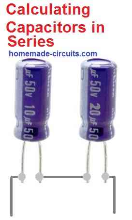
Here, we can see two capacitors, one having a value of 10 µF and the other having a value of 20 µF are connected in series.
Let's use the series formula to find out the result.
1/C_total = 1/C1 + 1/C2
1/C_total = 1/10 + 1/20 = 0.15
C_total = 1/0.15 = 6.66 µF
Connecting Capacitors in Parallel
When capacitors are connected in parallel, the total capacitance becomes the sum of the capacitance of each capacitor.
The formula for calculating the total capacitance of capacitors connected in parallel is:
C_total = C1 + C2 + C3 + ... + Cn
In order to connect capacitors in parallel, we simply have to follow the steps I have explained below:
- For polarized capacitors like electrolytic or tantalum, connect the positive terminals of all capacitors together. Next, connect the negative terminals of all capacitors together.
- Once this is done, the common positive and negative terminals ends of the combined capacitors become the input and output terminals. You can connect these terminals to a capacitance meter to get the results, or use the parallel formula to calculate the results.
- For capacitors without polarity such as disc ceramic, PPC, or MKT, you can connect the two ends of the capacitors in common without worrying about any polarity issues.
- Once connected, their common end terminals can be used to measure the capacitance with a capacitance meter, or the above explained formula can be used.
Solving a Practical Example
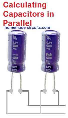
Now let;s see how we can solve a practical example where two capacitors are connected in parallel.
As shown in the figure below we can see two capacitors, a 10 µF and another 20 µF, connected in parallel.
Let's use the parallel capacitor formula to find the overall value of the above parallel connected capacitors.
C_total = C1 + C2
C_total = 10 + 20 = 30 µF
Solving a Series and Parallel Combination
How would you find the net capacitance value of a combination where both series and parallel connections are used.
Let's consider the following example:
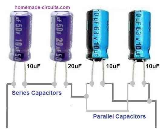
In the above image we can see on the left side a 10 µF and a 20 µF capacitors are connected in series. This series connected is further connected in series with two 10 µF capacitors connected in parallel.
Solving this type of series parallel combination is simple. We calculate the series and the parallel sets separately first, as shown below:
Series capacitors are 10 µF and 20 µF, therefore:
1/C_total = 1/C1 + 1/C2
1/C_total = 1/10 + 1/20 = 0.15
C_total = 1/0.15 = 6.66 µF
Parallel capacitors consists of two 10 µF capacitors, therefore:
C_total = C1 + C2
C_total = 10 + 10 = 20 µF
Thus, the above parallel capacitor becomes a single capacitor of 20 µF.
Similarly, the series capacitors become a single value of 6.66 µF.
Now, it is obvious that these two values are connected in series. Therefore we use the series formula to combine these two values.
1/C_total = 1/C1 + 1/C2
1/C_total = 1/20 + 1/6.66 = 0.20
C_total = 1/0.2 = 5 µF
Therefore, the net value of the above the above series, parallel capacitor combination is 5 µF.
How to Calculate the Voltage Rating of Series Parallel Capacitors
It is actually very simple.
When capacitors are connected in series, you must add their voltage ratings to find the total combined voltage rating of the series string.
When capacitors are connected in parallel, the voltage rating does not change, and remains the same for each capacitor. However, in parallel connection the µF value adds up as is evident in the parallel formula explained earlier.


Questions & Answers
Hi Mr. Swagatam;
I have a scrap fan (yj61/200 model) removed from the air fryer :
Its specs are 120V AC and 40W but When I measure its resistance value it is about 75 Ohm. However I will test it with the 220v AC voltage. Its sticker shows that it is 40W(0,34A) but according to the coil resistance it should be about 200W(1,6A). So I am not sure about its power. For the initial test can I use the capacitor (to limit the current) about 8uF? Please help for the matter.
Hi Suat,
When the fryer heats up its resistance will increase and it will end up consuming 40 watts only.
Yes you can use 8uF/400V for dropping the current which will eventually cause the 200V to drop to 120V across the fryer.
It is a safe a failproof method to convert 220V to 120V…. but for resistive loads only.
Sorry Swagatam but the result for me deduced from your comment is that this fan is not resistive load so it is not possible to test it by this method. Or if I would use the parallel one mega ohm resistance with the capacitor then is it possible or not? Or am I tottally wrong on understanding the matter? Could you please advise more?
Oh, I completely misinterpreted the question, sorry about that…I thought the air fryer was being used. Yes if the fan is used then the a capacitive current limiting might not be recommended. However you can try it with a series fuse and check how it responds…
Hi Swagatam;
Many thanks, I tested the fan and only used 2A fuse(auto switch type) and 2 pcs of 2,2uF (totally 4,5uF) capacitor. The result was OK and the load voltage was about 130AC. Also I tested it with the 2,2uF and then the load voltage was about 67AC. I think that the around 3,5uF will work.
That’s great Suat,
I was a little skeptical about using a capacitor to drop current and voltage for an inductive load, but it seems it is actually working for you.
Thanks for updating the info…
Sir,
Good evening,
Thanks a lot for your prompt reply.
Thanking you for your time,
Regards,
Sir,
Good evening,
Hope you are doing well. May I I request you to please suggest what is the correct way to use arduino, ULN 2003A, relays and stepper motors.
Thanking you for your time,
Regards,
Sorry Vishwa,
Unfortunately, my knowledge of Arduino and stepper motors is not good, so it is difficult for me to suggest a proper solution to your problem.
I hope someone else in this forum might be able to help you out in this regard.
Sir,
Good morning,
Very well explained and useful information. May I request you to please tell me about isolation capacitor.
Thanking you for your time,
yours faithfully,
Vishwa Mukh Bharadwaj
Good Morning Vishwa,
Thank you very much, I am glad you found the above post helpful.
Please tell me for which application do you want to use isolation capacitor, I will try to figure it out for you.
Sir,
Good afternoon,
Thanks for your prompt reply and encouraging words. In my project to control two 28BYJ-28 stepper motors there was problem with rotation of one of the motors. I have added one 220 micro farad capacitor between two circuits. Both motors are working normally. But I do not understand why and how to use capacitors correctly.
Once again thanks for your help,
yours faithfully,
Vishwa Mukh Bharadwaj
Good Afternoon Vishwa,
In your previous video link I can see that the two motors are well isolated using separate ULN2003APG ICs, so can you please specify where exactly do you want to add the capacitor for the isolation?
Sir,
Good afternoon,
Thanks for your prompt reply. I have added the positive terminal of the 220 microfarad electrolytic capacitor to the positive rail and pin 9 of the top ULN 2003 APG IC. The negative terminal of the electrolytic capacitor is added to the negative rail and pin 8 of top ULN 2003 APG IC.
Thanking you for your time,
yours faithfully,
Vishwa Mukh Bharadwaj
Thank you Vishwa,
So basically you have added the 220uF across the +/- supply terminals of the ULN2003 IC, that’s fine. But still it is not clear to me how and why do you intend to isolate the motors which are configured across separate ULN2003 ICs? I think they are already well isolated using separate buffer ICs.
Sir,
Good evening,
Thanks for your prompt reply. Your answers have definitely added to my knowledge. I suspected that there was a mismatch between code execution and physical execution.
I had also seen some motors with capacitors attached to its terminals. May be you can help me understand the role of capacitors in circuits with motors.
Thanking you for your time,
yours faithfully,
Vishwa Mukh Bharadwaj
Good Morning Vishwa,
You are right, motors must have a capacitor installed across there wire terminals, which ensures a smooth running of the motor without noise and also helps restrict voltage spikes which can otherwise cause interference with the associated electronic systems.
Sir,
Good morning,
Thanks for your prompt reply. I am extremely sorry to admit that instead of decoupling capacitor I asked help for isolation capacitor.
Thanking you for your time,
yours faithfully,
Vishwa Mukh Bharadwaj
Thank you Vishwa,
No problem, I am glad the issue is solved now.
Sir,
Good evening,
Thanks a lot for your prompt guidance and
patience.
Thanks for your time,
yours faithfully,
Vishwa Mukh Bharadwaj
You are welcome Vishwa.
Hi Mr Swagatam;
As known there are 2 pcs of parallel capacitors at the primary side of the smps transformers. My smps circuit has 2 pcs of 120uF capacitors too. So can I use 2 pcs of 150uF instead of those 120uF?
Hi Suat,
According to me it is fine to replace 120 uF capacitors with 150 uF capacitors.