In this post I have explained how LC oscillator circuits functions and we will be constructing one of the popular LC based oscillator - Colpitts oscillator.
What are Oscillators
Electronic oscillators are used in most of our daily used electronic gadgets ranging from digital clock to high end core i7 processor. Oscillators are heart of all digital circuits but, not only digital circuit employee oscillators but also analogue circuits uses oscillatory circuits.
For instant AM, FM radio, where the high frequency oscillation is used as carrier signal to transport message signal.
There are many different kinds of oscillators such as RC, LC, crystal etc. Each one of them has their own advantages and disadvantages. So there is nothing called best or ideal oscillator, we have to analyse the circumstance of our circuit and choose the best one which suit, that’s why we find wide range of oscillators in every day used gadgets.
LC Oscillators
Let’s dive into the explanation of LC oscillator.
The LC oscillator consists of an inductor and a capacitor as shown in figure below.
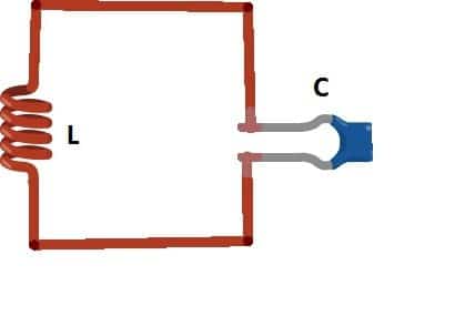
The value of the capacitor and resistor determines the output oscillation. So how do they generate oscillation?
Well, we need to apply external energy between L and C i.e. voltage. When we apply the voltage, the capacitor gets charged-up. When the supply is cut-off, the stored energy from capacitor flows to inductor and inductor starts building magnetic field around it until the capacitor completely gets discharged.
When the capacitor is fully discharged, the magnetic field around inductor collapse and induces voltage and charge-up the capacitor with opposite polarity and the cycle repeats.
The charge and discharge between L and C produces oscillation and this oscillation is called resonance frequency. However the frequency generation won’t last forever due to parasitic resistance which dissipates the energy in the oscillatory circuit in the form of heat.
To maintain the oscillation and use the oscillation with reasonable output strength, we need an amplifier with zero degree phase shift and feedback.
The feedback feed small amount of output from amplifier back to LC network to compensate the loss due to parasitic resistance and maintain the oscillation. Thus we can generate steady sine wave output.
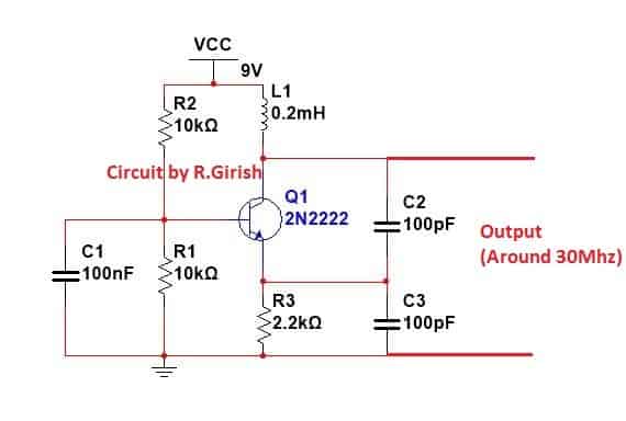
Application circuit:
Here is a colpitts oscillator circuit which can generate around 30 Mhz signal.
A couple of factors are essential to maintain oscillations in transistorized LC resonant crystal oscillator circuits. First, the feedback voltage arriving from the transistor collector has to be in phase with the actual input excitation voltage which is initially applied on the base of the transistor.
In other words the feedback link of the circuit should be positive or regenerative in nature.
Second, the quantity of the feedback energy to the base network should be adequately strong to compensate for the energy losses encountered in the base circuit. It can be necessary to evaluate the theory of Q prior to talking about oscillator functioning.
Q is described as a magnitude of caliber in a resonant circuit. Equivalent to the reactance divided by the resistance, the Q factor symbolizes the capability of the circuit to maintain oscillations using bare minimum feedback.
To put it briefly, the larger the Q the greater the efficiency of the resonance stage of the circuit. The inherent Q of quartz can be 10 million at 1 MHz frequency.
Even though Q mgnitude for a attached resonator crystal is diminished to ranges of 20,000 to more than a million, it is still well over the figures that's much superior to the top LC resonator or LC tank circuit.
LC oscillator with Crystal
The extremely large Q of the crystal oscillator substantially minimizes frequency drift triggered by temperature and the DC voltage fluctuations.
Furthermore, crystal-controlled oscillators generate a reduced amount of noise compared to traditional LC tank based oscillator circuits, and hence produce a healthier output signal. The easiest crystal oscillator is made up of solitary BJT using a basic feedback network.
Figure 1-a displays a block diagram of a universal crystal oscillator. In this concept , an NPN BJT based amplifier can be seen configured with three feedback circuits. Suitable DC bias is presumed to be present although not revealed in the diagram.
Figure 1-b is an comparative circuit built using the parts L1 and C1, and C2 as shown. Each and every crystal oscillator circuit discussed below are designed to work with exactly the same fundamental topology, by using a minimum of two capacitors and an inductor. The crystal could be seen as an element of the feedback circuit.
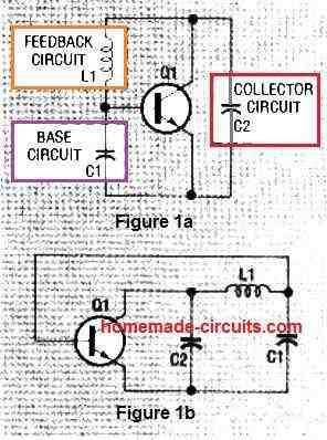
Capacitors C1 and C2 consist of residual transistor and junction capacitance. Capacitor C2 is similar to a parallel network of an inductor and a capacitor.
This LC pair works like the crystal's third overtone selector since it exihibits capacitive nature only at the crystal's overtone frequency, and inductive property at its fundamental frequency.
Therefore, an inductor positioned at C2 inhibits oscillation at the crystal's fundamental frequency. Along with amplification and feedback, an oscillator circuit additionally needs a limiting factor, that occurs when a rise in the input signal no more results in a rise in the output signal. Because of this, the oscillator's output attains a boundary and continues to be in this boundary.
The typical Colpitts crystal-controlled oscillator possesses a stringent load and tuning specifications, while the a pair of semi-isolated models are much less demanding, and are proposed as far better options for general-purpose applications.
In case you are looking for a very accurate output frequency, the Pierce crystal oscillator is the one you must opt for.
On the other hand, if you just want to try things out with oscillators, you may realize that the Butler circuit is able to oscillate without depending on a crystal, and you could test the results using a crystal in or out.
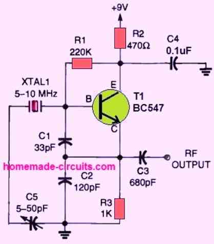
General Colpitts oscillators
A couple of variations of the Colpitts crystal-controlled oscillator are introduced in this article: the standard and the semi-isolated.
The standard circuit, demonstrated in Fig. 2, is dependent on the specifications of both, the crystal and load resistance. Additionally, its output power is restricted to less than 50 % of the crystal's power dissipation. However, it is yet considered to be one of the favorites.
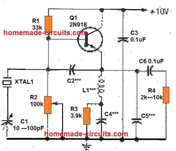
Resistors R1, R2, and R3 provide the DC bias to the transistor Q1. Potentiometer R2 is used to enable up to around 1.5 milliamperes of emitter current. Capacitors C3, C4, and C6 work like a bypass elements for the radio frequency at XTAL1's working frequency (fundamental or overtone).
Capacitor C2 operates like the feedback base circuit, equivalent to the capacitor C1 as explained in in Fig.1. When the circuit is working at the XTAL1's operating frequency, L1 and C5 exhibit a net capacitive reactance, and therefore function as the collector circuit feedback capacitor, just like C2 in Figure1.
When overtone crystals are utilized, L1 and C5 behave just like an overtone selector, blocking oscillation at the crystal's fundamental frequency. Capacitor C1 which is an adjustable trimmer, tweaks the feedback component L1. As the C1 value is reduced, the oscillator's output frequency increases.
Another Crystal Controlled Colpitts Oscillator
Next up is a tapped capacitor setup, also known as a Colpitts oscillator circuit, which is controlled by a crystal. The feed-back ratio required to sustain oscillation is determined by the values of C1 and C2.
The values of C1 and C2 should be chosen for a particular frequency in order to achieve the best level of output and frequency stability. Here, some experimentation will be necessary. Experimental research is enjoyable and a useful approach to learn.
Simple RC Oscillator Circuit
An oscillator can be also built using just a resistor, capacitor network along with a transistor. Here the transistor base terminal is kept unconnected, only the emitter and collector are used.
The complete circuit diagram for this RC oscillator can be seen in the following image:
Simple LC RF Oscillator
The Colpitts circuit presented in the following figure is a simple LC RF oscillator that can work nicely between around 100kHz to 50MHz or higher. Transistor TR1 is configured like a source follower, and the tiny coupling via the T1 inductor winding on is implemented to generate a positive feedback and for stepping up the voltage required for sustaining the oscillation.
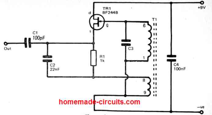
The primary winding of T1 along with C3 form the LC tuned circuit. This establishes the operating frequency of the LC oscillator circuit. R1 works like the source load for TR1 at the supplied DC, however TR1 gets bypassed with an AC through C2 causing the coupling winding of T1 to form the real source load for Tr1.
The output signal of the oscillator is derived through the TR1 source via the DC blocking capacitor C1. Capacitor C4 is simply works like a supply decoupling capacitor. In case an adjustable tuning oscillator is expected, C3 could be easily be replaced with a variable capacitor, or a collaboration of fixed and variable capacitors to enable the required tuning range.
For medium and high frequency LC oscillator, many hobbyists employ ready-made coils nowadays, and these usually offer improved and much more predictable frequency outputs, than the basic home-wound coils.
To build T1 at home, just wind two sets of coils (6 to 1, and 8 to 9) one above the other over a small ferrite rod. The number of turns can be experimented for getting different frequency outputs.
The key thing to remember is that the phasing of the smaller coupling winding has to be properly connected, otherwise the circuit will not oscillate. However, the best technique of connecting the smaller coil can be implemented by only through some trial and error.


Questions & Answers
Would to R/C one work with a lower voltage?
No, it won’t…
I don’t under stand why not.
Because the BJT is configured in negative resistance mode, which is not the standard way of connecting a BJT and requires higher voltage to operate…
Makes sense, thanks!
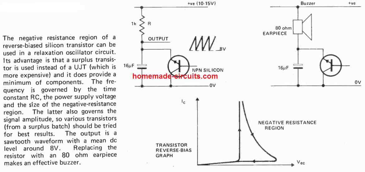
A weird one!
I built a Colpitts like the one up on top, except the base has no cap in mine. 16.4V power from a pair of 9V rechargeable batteries. C, 471. R3, 1K. R2, 100K. R1, 22K. L1, About 4″ diameter, 40 ohms DC resistance, #32 cu magnet wire, a metal detector transmitter coil. It works, pretty good, in fact. It ran at 45 KHz, about where I want it. While the waveform sucks, 70 volts p-p output has me wondering why. The voltage was measured on a Tektronix 2465A oscilloscope. It had similar results with several transistors, but the best one so far was a National Semi 105-1704. No documentation, TO-92.
Why have I got 70 volts p-p measured on the collector?
Thanks for the interesting information!
You might have built something like this:
https://www.homemade-circuits.com/8x-overunity-circuit-using-joule-thief/
If possible please provide the circuit diagram, you can send it to my email ID.
The diagram is identical to the first one on this page, but remove the base cap to ground.
R1 = 22K, R2 = 100K, R3 = 1K, C = 471, L = 3.7mH. Ce = 102.
I would love the same results with a nice sine wave.
In your case the circuit is simply working like a boost converter, and that is why you are seeing a boosted voltage of 70 volts.
For a sine wave you could probably try putting the base/ground capacitor back, and reduce its value to some lower level.
???? found out that 7pF = 0.000000000007 ampere second/volt.
Have no idea what that does in a self resonating coil. Will it create a standing wave?
P.s. this is based on a one time charge of the 7 pf cap.
I came to that conclusion imagining 409 cycles at a frequency of ca. 58 MHz how long that would take.
The 22 mA I got by using Ohms law.
9 V and the coils reactance of the coil 405.847 Ohm. => power dissipation 199.52262 mW.
But I might be far off there.
A good 9V PP3 battery will be capable of powering a 22mA load for around 500 / 22 x 0.7 = 15 minutes or at the least 10 minutes.
Sorry, maybe I’m not expressing myself clear enough. I understand that you focus on how long the battery will last. That was not my question. I wanted to find out how long a one charge of the LC tank would last.
That is, the 9V battery charges the 7pF cap before getting isolated and the tank starts it’s oscillating. So how long will the oscillating last before dies out, or needs reloading.
If the 7pF is connected across the supply rail and you are asking how long the charge inside the 7pF can sustain the oscillation in the LC circuit once the battery power is cut off, then that will need some calculation?
Indeed, and there I’m not sure I did it right.
I wrote “The coils power use, based on its resistance, would be 199.52262 mW / 22.16918 mA.
Would this give an amount of 409 oscillations before all power is used up?”
Here I was referring to the power inside the tank aka the 7pF cap.
Maybe I should have looked how much power is stored in the cap?
Something like 1 F = 1 A/sec?
The case is, that I wish (sometimes ppl wish the imposible) to know if the charge of the 7pF could be sufficient to drive the high frequency trafo from 9 to 180 V which output would drive the next HF trafo to 960 V and from there down to 230 V AC and simultaneously to 9 V AC to drive our first coil.
Electricity travels with the speed of light, so maybe a few ms would suffice?
You mean to say the 7pF is itself the “C” in the LC circuit and you want to know how many oscillations it can complete with one full charge on the 7 pF.
That’s very complex to solve, because the oscillations will be damped oscillation which will die out slowly from t = 0 to t = infinity.
The formula will be a differential type.
Dear Sir, I am seeking your help in validating my thinking/calculations.
I have an air coil with these characteristics calculated in
Coil32 (One-layer coil calculation)
Inductance L = 1.114 µH
Number of turns N = 3.0
Reactance of the coil X = 405.969 Ohm
Self-capacitance Cs = 3.297 pF
Self-resonance frequency Fsr = 58.167 MHz
Q-factor of the coil Q = 739.0
I want to make a LC tank where this coil is the primary of an air coil trafo.
Hence I calculated that I need a 7 pf cap to resonate in the coils self resonance.
Voltage applied is 9V from a battery.
Further calculations (I use available calculators, not calculations derived from formulas) give me these values.
The coils power use, based on its resistance, would be 199.52262 mW / 22.16918 mA.
Would this give an amount of 409 oscillations before all power is used up?
Dear Sol, Calculating physically can be a quite time consuming, since there are many conversions required in the process….the easiest way is to use any online resonance calculator software and confirm the results through it
As I did explain, I do use online calculators. None of them give an indication how long the oscillation will be alive. Everybody says, if it were an idealistic case, the oscillation will go on forever, but resistance in the circuit will kill the oscillation after some time. I wanted to be able to determine how long this ” time” is. If my assumption of 409 cycles is right, it would mean some ms? That would probably to short to obtain any useful operation.
OK, go it, but 22 mA is not a very high current for a 9V PP3 battery with 500 mAh capacity, it should be able to sustain it for quite sometime….from where did you get a few millisecond time?
Low pass filter?
I’ve been looking for a simple direct frequency changer without luck. In this case from 180v AC 1.5 MHz output to same voltage 2.17 MHz. as input for a next stage.
I was thinking using the right capacitor would do the trick.
Do you have any suggestions?
Yes capacitors values can eb changed for getting the desired frequency, or you can also modify the following circuit for the same:
https://www.homemade-circuits.com/1-hz-to-1-mhz-frequency-reference-generator-circuit/
Thanks for putting the circuit on line however I have tried to simulate this in LTSpice and I get a frequency 1.5MHz, which is the value I get using the formula f = 1/ (2*PI*SQRT(CL))
I’m looking for a simple 30MHz oscillator and was hoping this would work but I cannot get it to run at 30MHz
If you are using the formula, in that case you can adjust the part values to get 30 MHz.