In this post I have explained how to correctly calculate inverter parameters with associated stages such as battery and transformer, by calculating the matching the parameters correctly.
Introduction
Making an inverter all by yourself can be definitely lot of fun. However if the results are not satisfactory can completely spoil the whole purpose of the project.
Installing and configuring the various inverter parameter like the battery and the transformer to with the actual assembled circuit needs special care and attention for deriving optimal results from the assembly.
In this article I have explained how to calculate and match a battery and transformer wit the relevant circuit and also enlightens regarding the possible faults that might be encountered and the respective troubleshooting procedures.
The article enlightens the many newcomers with some of the important clues, which might be helpful while configuring an inverter circuit with the battery and the transformer, so that efficient and optimal results can be achieved.
Calculating Transformer and Battery Specs
While making an inverter, two calculations must be broadly taken into account, viz. the transformer and the battery ratings.
1) The transformer must be rated higher than the maximum load that is expected to be used with the inverter. For example if the intended load is 200 watts, then the transformer must be rated at minimum 300 watts. This will ensure a smooth running of the inverter and less heat generating from the transformer.
The voltage rating of the transformer must be slightly lower than the battery voltage for square wave inverters.
However, for concepts involving PWM or SPWM, it should be equal to the average voltage (x 2) applied at the gates of the MOSFETs.
This can be measured by measuring the average DC voltage applied at the gate of the MOSFETs from the oscillator stage and then multiplying it by 2. So, suppose your battery voltage is 12 V, but because of PWM your average switching voltage from the oscillator shows 3.5 V DC, that implies your transformer must be rated at 3.5 x 2 = 7V. Meaning its primary should be rated at 7-0-7 V and not 12-0-12 V.
2) And the battery Ah must be rated 10 times more than the maximum current rating of the load. For example if the battery is 12V rated and the load 200 watts, then dividing 200 with 12 gives us 16 amps. Therefore the battery Ah must be 10 times of this amp rating, that is 160 Ah. This will ensure your battery runs with a healthy 0.1C discharge rate and provides a back up of around 8 hours.
Calculating MOSFET Rating
Calculating MOSFET for an inverter is actually quite simple. One has to take into account the fact that MOSFETs are nothing but electronic switches, and must be rated just like we rate our mechanical switches. Meaning the MOSFET's voltage and current ratings must be adequately selected so that even at the maximum specified load, the MOSFET working is well within its breakdown level.
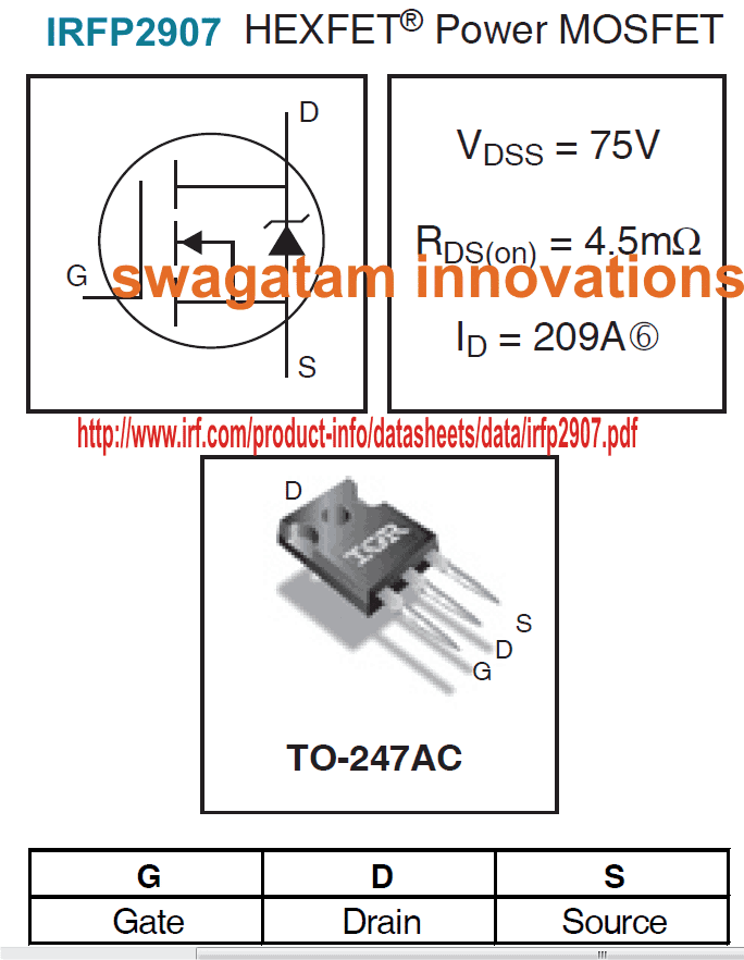
To ensure the above condition, you can refer to the datasheet of the mosfet and check the Drain-Source Voltage and the Continuous Drain Current parameters of the device, such that both these values are well above the load's maximum consumption values, or are selected with appreciable margins.
Suppose if the load is rated at 200 watts, then dividing this with the battery voltage 12V we get 16 amps. Therefore the MOSFET could be selected with voltage ratings anywhere between 24V to 36V as its Drain-Source Voltage (Vdss), and 24 amp to 30 amp as its Continuous Drain Current (Id).
Take the example of the MOSFET in the image above, here the maximum tolerable voltage Vdss of the specified MOSFET is 75V, and maximum tolerable current Id is 209 amps, when operated with proper heatsink. It means this MOSFET can be safely used for all applications where the load wattage is not more than 14000 watts.
Although in real life the load handling capacity may be even lower than this.
As a rule of thumb, make sure the Vdds x Id value is at least 30% higher than the max load wattage, and the MOSFETs are adequately heatsinked.
This takes care of the MOSFETs, and ensures a perfect working of the devices even at full load conditions, but do not forget to mount them on appropriately dimensioned heatsinks.
After procuring all the necessary components as explained above, it would be important to get them checked for compatibility with one another.
Only the battery, which is one the most crucial member, hopefully will not require any prior checking, because the printed rating and the charged voltage conditions should be sufficient to prove its reliability. It is assumed here that the condition of the battery is good and it’s relatively new and “healthy.”
Calculating MOSFET Switching Parameters
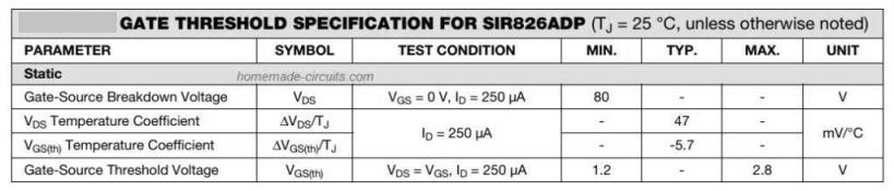
The gate resistor affects the charging and discharging of the MOSFET's gate capacitance which determines the switching speed.
Turn-on/Turn-off Time:
ton/off = Rg * Cg
Where:
Rg = Rg(ext) + Rg(int), the total gate resistance (external + internal).
Cg = Qg / Vgs, the equivalent gate capacitance.
Vgs is the gate drive voltage.
The peak current required to charge/discharge the gate can be calculated using the formula:
Ig = Vgs / Rg
The power dissipated in the gate resistor during switching can be calculated using the formula:
PRg = fs * Qg * Vgs
Where:
fs is the switching frequency.
Qg is the total gate charge.
The rate of voltage change during the switching period is:
dv/dt = Ig / Coss
Where Coss is the MOSFET's output capacitance.
Power losses is simply equal to the sum of conduction and switching losses.
Formula for Calculating the Conduction Losses:
Pcond = ID2 * RDS(on) * D
Where:
ID is the drain current.
RDS(on) is the on-resistance.
D is the duty cycle.
Formula for Calculating the Switching Losses:
Psw = 0.5 * VDS * ID * (ton + toff) * fs
Where ton and toff are determined by Rg.
To select Rg:
Use the switching time formula:
ton/off = Rg * Qg / Vgs
Solving for the Rg to achieve the desired switching time.
Ensuring the gate drive current:
Rg <= Vgs / Ig(max)
Check that Ig(max) is within the capability of the driver.
Adjust for dv/dt and EMI:
Increase Rg to reduce EMI and ringing but avoid overly slow switching.
Use a fast recovery or Schottky diode with a reverse voltage rating at least equal to Vgs.
The diode allows faster turn-off while controlling the turn-on speed with Rg.
Example Calculation:
MOSFET Parameters:
Qg = 50 nC
Vgs = 10 V
Gate driver current capability = 2 A
Calculations:
Selecting the ton/off:
The Desired ton/off = 100 ns
Rg = ton / Cg = 100 ns / (50 nC / 10 V) = 20 ohms
Check Ig:
Ig = Vgs / Rg = 10 / 20 = 0.5 A (looks well within driver capacity).
Confirming the switching losses:
For fs = 100 kHz, VDS = 50 V, ID = 10 A:
Psw = 0.5 * 50 * 10 * 200 ns * 100 kHz = 0.5 W
Checking the transformer
The transformer, which is the most important component of the inverter, surely needs a thorough technical assessment. It may be done as follows:
The rating of the transformer can be best checked in the reverse order, i.e. by connecting its higher voltage winding to the AC mains input and checking the opposite winding for the specified outputs. If the current ratings of the lower voltage section are within the maximum limits of a regular multi-tester (DMM), then it may be checked by switching ON the above AC and connecting the meter (set at, say AC 20 Amp) across the relevant winding.
Hold the meter prods connected across the winding terminals for a couple of seconds to get the readings directly on the meter. If the reading matches with the specified transformer current, or at least is close to it, means your transformer is OK.
Lower readings would mean a bad or a wrongly rated transformer winding. The assembled circuit broadly needs to be checked for proper oscillation outputs across the bases of the power transistors or the MOSFETs.
This may be done by connecting the circuit to the battery, but without including the transformer initially. The checking should be done using some good frequency meter or if possible using an oscilloscope. If the above gadgets are not there with you, a crude testing can be performed using a pair of ordinary headphones.
Connect the headphone jack to the bases of the relevant power transistors; you should get a strong humming sound in the headphones, confirming a sound functioning of the oscillator stages.
The above confirmations should be enough to prompt you to configure all the sections together. Connect the transformer to the relevant transistor or the power devices terminals; make sure the power devices are correctly integrated with the oscillator stage.
Installing the Final Inverter Set up
Finally the battery may be connected to the power inputs of the above configuration, again do not forget to include an appropriately rated FUSE in series with the battery positive. The output of the transformer now may be attached with the specified maximum load and the power may be switched ON.
If everything’s is wired up correctly, the load should start operating at its full fledged power, if not, then something’s wrong with the circuit stage. Since the oscillator section was appropriately checked before the final installations, surely the fault may lie with the power device stage.
If the fault is associated with low power outputs, the base resistors may be tweaked for possible faults, or may be reduced by adding parallel resistors to their existing base resistors.
The results may be checked as discussed above, if the results are positive and if you find improvements in the power outputs, the resistors may be further modified as desired, until the expected power output is delivered.
However, this may lead to further heating of the devices and due care must be observed to keep them under check by either including cooling fans or increasing the heatsink dimensions.
However if the fault is accompanied with blowing of the fuse would mean a definite short circuit somewhere in the power stage.
Troubleshooting the Inverter Connections
The problem may also indicate a wrongly connected power device, a blown-of power device due to a possible shorting between the power device’s output terminals or the any of the terminals that needs to be perfectly kept aloof of each other.
Having explained a few of the above possibilities while configuring an inverter optimally, a thorough knowledge regarding electronic becomes an absolute necessity from the part of the individual who may be involved with the construction, without which the proceeding with the project may somehow get jeopardized.

Questions & Answers
Very helpful but how to come up with proper turn on and turn off time for the MOSFET.how to calculate for resistors?
Thanks for your feedback, The switching time for a MOSFET is normally not a critical factor, and the gate resistor can be a 10 ohm resistor for most of the applications, with a reverse diode across this resistor, however for high frequency and high current loads, the ON/OFF time and the gate resistor can become critical, so they must be optimized, i have provided the required calculations in the article for your reference…
Thank you a lot Mr. Swagatam for all your sacrifices to Hobbyists.
I built a H-bridge inverter using an sg3524 ic as it’s oscillation generator. The system is actually a12v system and works very well on 12v 100ah battery, but burns the whole MOSFETs when the battery is paralled to 12v 200ah. Here, after winding my transformer, I got 12.7vac on the primary side, while the actual gate-source voltage of my oscillator is around 6.4v. Based on your illustration above sir, could I have violated the power rating and is your direction applicable to full bridge inverters?. Please do help me out on this path of confused. Thanks
Thank you Chinomso,
I hope you measured the oscillator frequency across the gate/source of the low-side MOSFETs.
Actually this average voltage must be multiplied by 2 to get the exact transformer primary voltage rating, because the oscillator voltage is the average of both the ON and OFF periods, but we want the average value of only the ON periods. Therefore to compensate the OFF time we must multiply the average gate voltage of the low side MOSFET with two.
In your case it is 6.4 * 2 = 12.8V…which means your 12.7V transformer is perfectly suitable for the application.
Thank you so much ones again Mr. Swagatam, your assistance is awesome. I actually had to double the winding on the transformer primary, making it thicker this time, and I also had to replace the MOSFET’s pull down resistors from 1k to 4k7 and guess what, the whole MOSFETs blowing up stopped. However, another issue came up. The voltage of the transformer output rose to 256volts, and each time I tried to vary the feedback to just below the 250v mark, the transformer starts to thrump like an ignited car about to takeoff. This is just about the only issue I have now. Please help again. I appreciate.
No problem Chinomso,
I am always glad to help!
Are you using a bridge rectifier for the feedback loop? If yes, you can try adding a capacitor at the output DC side of the bridge rectifier, and see if that helps to calm down the inverter.
The capacitor can be a 100uF/25V capacitor.
I want to design a pure sine wave inverter with a carrier frequency of 10khz and pwm frequency of 50hz, the battery voltage is 48v and my transformer secondary is wond for 26v for good transformer regulation. Now I want to select the mosfets and my question is do I select mosfets with vdd of 48v battery * 1.5 for mosfets not to damage or I should select mosfets with 26v transformer_voltage * 1.5
Also how do I calculate the wire size for second the load is 5000watt is it 5000/48v_battery voltage or 5000/26v_transformer voltage.
Waiting for your reply thanks.
You must consider the 48V not the 26V while calculating the parameters.
Thanks for your reply.
I have another question which is: How do I calculate the secondary wire size of the transformer, the inverter is a pure sine wave inverter load is 5000 watt and battery is 48v I know the secondary voltage will be 26v so the secondary wire size will be 5000/48v or 5000/26v to get the secondary wire size for the pure sine wave inverter transformer, the transformer is a low frequency transformer of 50hz, iron core type.
Thanks
For the wire size you may have take 26V into account, for dimensioning the wire current handling capacity.
Good day Team
I will like you to help me here ..i have inverter 1200VA Mecer that is not giving output voltage and when i check my Transistors they are fine on the MOSFET Side.
What could be the main problem on this one….Thanks your help will be much appreciated
Hi, did you check the whether the MOSFETs are getting the gate frequency from the oscillator stage or not?
Because if the MOSFETs don’t get a PWM frequency at their gates they won’t oscillate and won’t cause any voltage output.
Who’s so ever that is having difficulties in building inverter should let me know just chat me up learn froe the one you don’t know
+2348144714713
I am having difficulties selecting MOSFET or knowing the number of MOSFETs to be parallel in my SMPS based on safe area operation.
Please provide the specifications of the SMPS.
Sir,
How could I read the amps of the transformer of the lower voltage?According to the article, Will it be in series with a load?
Or parallel as it’s winding terminal?
Ayodele, The load and the ammeter should be in series with the transformer supply.
hello sir, do you have any article of 12v source and ups with backup battery that you can recommend is for an access control project
Hello Marcelo, I have a couple of UPS based articles on this website which you can refer to:
Simple Online UPS Circuit
4 Simple Uninterruptible Power Supply (UPS) Circuits Explored
Dear Sir
Please sir, how can I know original lead acid battery to buy? Or which type of it is original?
2. How do I test if a lead acid battery is OK in case of buying a fairly used or used battery?
Thank you sir
Hi Godfrey, you can do an online search and read the reviews to know which battery is the best and which are from a reputed brand.
It can be difficult to test a battery quickly, you will need at least some hours to discharge the battery through a circuit and then analyze its backup time and current.
https://www.homemade-circuits.com/precise-battery-capacity-tester-circuit-backup-time-tester/
Hello sir, that’s a very superb article you have got here, thanks to your website am now understanding many things difficult before, pls I have gone through the article and I understand what you have said but I need to ask a question pls,
After calculating the mosfet/transistor vdss…… and others how are am I to calculate the number of mosfets/ transistors needed for the the intended inverter watt, say for example am to use 16 mosfets for 1000 watts, how am I to calculate and know that am to use exactly 16 mosfets for 1k Watts.
Thanks for answering. Remain blessed
Thank you Anthony, the VDDS and ID indicate the maximum tolerable power the mosfet can handle, but we need to provide a 50% margin so that the mosfet can work with normal heatsinking. The product of the VDDS and ID and 50% will determine the total wattage the mosfet can handle….you can divide the inverter wattage with this result to get the total number of mosfets required to be added in parallel
Hi swagatam
Really appreciate ur work,keep up gud work excellent information on inverter discrete comonents
Thank you Suresh for your kind feedback!
Hi, I am researching inverters as I would like to build one sometime soon, one thing on my mind is choosing the right transformer, I would like to buy one instead of making it myself. Your article stated that I should put a load threw the mosfet and measure the voltage before I could choose the right transformer is that correct?
Hi, yes you can do that, measure the voltage across the load, or the drain/source terminals, this will be your transformers primary voltage rating
Dear sir,
please sir, in respect to checking the transformer for the specified secondary current.
1. What alternate method can be used to measure the current if AC current range on the DMM is below the value specified?
2. And again, for DMM that doesn’t have AC current test, can the secondary of the transformer be rectified with full bridge or half bridge, and then setting the DMM to DC current range to measure the current? Will the result be the same if it was to be measured using AC ammeter.
Hello Godfrey, you can measure it by applying shunt resistor method. Put a known resistor low value high wattage resistor across the transformer wires, check the AC voltage across it, use the following ohms law to get the current value
I = V/R, where V = voltage reading on the meter, R = value of the resistor
For DC meter, first convert the AC to DC using bridge rectifier and repeat the above process across the output of the bridge.
Thank you very much sir. I really appreciate your time and this great offer of help.
You are welcome Godfrey!
Please how do i know the Ah of the transformer i wind by my self. I used 19 guage copper wire
You can do it by connecting an ammeter across the secondary wires of the transformer for a few seconds and note the current reading on the meter
Pls can I use two different kind of power mosfet in building one Inverter because I don’t have enough mosfet?…i.e irf 1010e and irf4110
yes you can, just make sure their technical specs are similar,…. or the max V and I specs of the required inverter output is 50% lower than the max rating of the MOSFETs
Hi,
Thank you for the post. I am trying to make a pure sign wave inverter using SPWM generated using Arduino. And i am planning to use high frequency PWM capability of Arduino to produce 62kHz PWM signal and use that to simulate 50Hz sine wave. As a result transformer will see 62Khz pulses. In this case for best efficiency do I need to use a high frequency ferrite core transformer calculated/designed for 62KHz or a regular transformer calculated/designed for 50Hz?
Best Regards
Hi, you will need a ferrite core based transformer for handling the 62kHz carrier frequency
Hello sir swagatam, please enlighten me here; which mosfets are more efficient to use in inverters involving high voltage say from 24,36,48,60,72,96 extra??
1. Mosfets with high RDSon?
2. Mosfets with low Reason?
The reason am asking you this is that I’ve tried designing a 24v Inverter using irfz44N and irfp1404 in vain. But if I design a 12v inverter,it functions well,what might be the problem? Am using cd4047 for osciliation from one of your articles sir. Or let me know if there’s something else I need to do when it comes to Inverter with high input voltage? I have a 5000w transformer,2×200Ah batteries and I need to design a 24v/220v 5000w inveter. Look forward to hearing from you soon.
Hello Evans,
Higher RDSon will cause more heat dissipation on a MOSFET and vice versa. So lower RDSon is preferable for greater efficiency.
Both the MOSFETs that you have mentioned are suitable for a 24 V inverter, however irfp1404 is better suited due to lower RDSon.
There could some other issue in your inverter, because designing a 24V inverter is as easy as designing a 12 V inverter.
For 5kva output you may have to add many of those MOSFETs in parallel, and use a 20 V transformer for a 24V battery
Sir my transformer is 17v
then it is OK….
Thank you for your response. From your opinion,what might be the problem? Coz the circuit I used is from your articles?
Evans, Whether it is from my site or any other, the operating voltage level can never be an issue, as long as the transformer and the MOSFETs are appropriately matched.
Make sure your oscillator IC circuit gets a stabilized voltage, which doesn’t exceed its maximum tolerable limit. And the MOSFets are also protected with external reverse diodes
For a stabilized voltage circuit for the oscillator you can refer to the following article:
500 Watt Inverter Circuit with Battery Charger