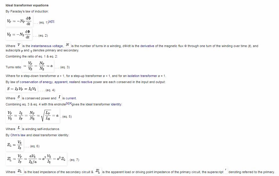
According to the definition given in Wikipedia an electrical transformer is a stationary equipment that exchanges electrical power across a couple of closely wound coils, through magnetic induction.
A constantly altering current in one winding of the transformer generates a varying magnetic flux, which, consequently, induces a varying electromotive force over a second coil built over the same core.
Basic Working Principle
Transformers basically work by transferring electrical power in between a pair of coils through mutual induction, without depending on any form direct contact between the two winding.
This process of transfer of electricity through induction was first proved by Faraday's law of induction, in the year 1831. According to this law the induced voltage across two coils is created due to a varying magnetic flux surrounding the coil.
The fundamental function of a transformer is to step up or step down an alternating voltage/current, at different proportions as per the requirement of the application. The proportions are decided by the number of turns and turn ratio of the winding.
Analyzing an Ideal Transformer
We can imagine an ideal transformer to be a hypothetical design that may be virtually without any form of losses. Moreover, this ideal design may have its primary and secondary winding perfectly coupled with each other.
Meaning the magnetic bonding between the two winding is through a core whose magnetic permeability is infinite, and with winding inductances at an overall zero magnetomotive force.
We know that in a transformer, the applied alternating current in the primary winding tries to enforce a varying magnetic flux within the core of the transformer, which also includes the secondary winding encircled around it.
Due to this varying flux, an electromotive force (EMF) is induced on the secondary winding through electromagnetic induction. This results in the generation of flux on the secondary winding with a magnitude that's opposite but equal to the primary winding flux, according to Lenz'z law.
Since the core carries an infinite magnetic permeability, the entire (100%) magnetic flux is able to get transferred across the two winding.
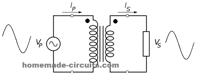
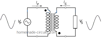
This implies that, when the primary is subjected to an AC source, and a load is connected to the secondary winding terminals, current flows through the respective winding in directions as indicated in the following diagram. In this condition the core magnetomotive force is neutralized to zero.
Image courtesy: https://commons.wikimedia.org/wiki/File:Transformer3d_col3.svg
In this ideal transformer design, since the transfer of flux across the primary and secondary winding is 100%, according to Faraday's law the induced voltage on each of the winding will be perfectly proportional to number of turns of the winding, as displayed in the following figure:
Test Video Verifying the Linear Relationship between Primary/Secondary Turn Ratio.
TURNS AND VOLTAGE RATIOS
Let's try to understand the turn ratio calculations in detail:
The net magnitude of voltage induced from the primary to secondary winding is simply determined by the ratio of the number of turns wound over the primary and the secondary sections.
However, this rule only applies if the transformer is close to an ideal transformer.
An ideal transformer is that transformer which has negligible losses in the form of skin effect or eddy current.
Let's take the Example of the figure 1 below (for an ideal transformer).
Suppose the primary winding consists of around 10 turns, while the secondary with just a single turn winding. Due to electromagnetic induction, the lines of flux generated across the primary winding in response to the input AC, alternately expand and collapse, cutting through the 10 turns of the primary winding. This results in a precisely proportionate amount of voltage been induced across the secondary winding depending on the turn ratio.
Figure (1)
Since the secondary has only a single turn, it experiences a proportionate magnetic flux across its single turn relative to the 10 turns of the primary.
Therefore, since the voltage applied across the primary is 12 V, then each of its winding would be subjected with a counter EMF of 12/10 = 1.2 V, and this is exactly the magnitude of voltage that would be influencing the single turn present across the secondary section. This is because it has a single winding which is capable of extracting only the same equivalent amount of induction that may be available across the single turn over the primary.
Thus the secondary with a single turn would be able to extract 1.2V from the primary.
The above explanation indicates that the number of turns over a transformer primary corresponds linearly with the supply voltage across it and the voltage simply gets divided by the number of turns.
Thus in the above case since the voltage is 12V, and the number of turns are 10, the net counter EMF induced over each of the turns would be 12/10 = 1.2V
Example #2
Now let's visualize the figure 2 below, it shows a similar type of configuration as in figure1. expect the secondary which now has 1 additional turn, that is 2 numbers of turns.
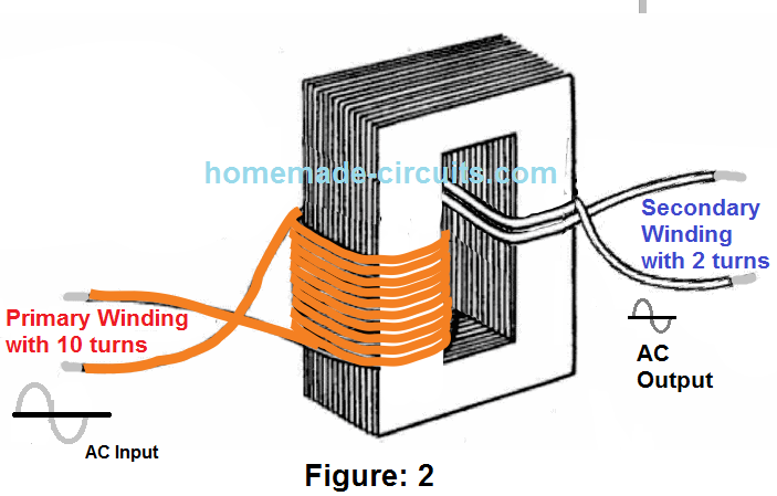
Needless to say, that now the secondary would be going through twice as many lines of flux compared to the figure 1 condition which had just a single turn.
So here the secondary winding would read around 12/10 x 2 = 2.4V because the two turns would be influenced by a magnitude of counter EMF that may be equivalent across the two winding on the primary side of the trafo.
Therefore from the above discussion in general we can conclude that in a transformer the relation between the voltage and number of turns across the primary and the secondary are quite linear and proportional.
Transformer Turn Numbers
Thus, the derived formula for calculating the number of turns for any transformer can be expressed as:
Es/Ep = Ns/Np
where,
- Es = Secondary Voltage,
- Ep = Primary Voltage,
- Ns = Number of secondary turns,
- Np = Number of Primary turns.
Primary Secondary Turn Ratio
It would be interesting to note that the above formula indicates a straightforward relation between the ratio of the secondary to primary voltage and secondary to primary number of turns, which are indicated to be proportionate and equal.
Therefore the above equation can be also expressed as:
Ep x Ns = Es x Np
Further on, we can derive the above formula for solving the Es and Ep as shown below:
Es = (Ep x Ns)/Np
similarly,
Ep = (Es x Np)/Ns
The above equation shows that if any 3 magnitudes are available, the fourth magnitude could be easily determined by solving the formula.
Solving Practical Transformer Winding Problems
Case in point #1: A transformer possesses 200 number of turns in the primary section, 50 number of turns in the secondary, and 120 volts connected across the primary (Ep). What could be the voltage across the secondary (E s)?
Given:
- Np = 200 turns
- Ns = 50 turns
- Ep = 120 volts
- Es = ? volts
Answer:
Es = EpNs/Np
Substituting:
Es = (120V x 50 turns)/200 turns
Es = 30 volts
Case in point #2: Suppose we have 400 number of turns of wire in an iron-core coil.
Assuming coil is required to be employed as the primary winding of a transformer, Calculate the number of turns that needs to be wound on the coil to acquire the secondary winding of the transformer to ensure a secondary voltage of one volt with a situation where the primary voltage is 5 volts?
Given:
- Np = 400 turns
- Ep = 5 volts
- Es = 1 volts
- Ns = ? turns
Answer:
EpNs = EsNp
Transposing for Ns:
Ns = EsNp/Ep
Substituting:
Ns = (1V x 400 turns)/ 5 volts
Ns = 80 turns
Bear in mind: The ratio of the voltage (5:1) is equivalent to the winding ratio (400:80). Occasionally, as a substitute for particular values, you find yourself assigned with a turn or voltage ratio.
In cases like this, you could simply assume any arbitrary number for one of the voltages (or winding) and work out the other alternative value from the ratio.
As an illustration, suppose a winding ratio is assigned as 6:1, you could imagine a quantity of turn for the primary section and figure out the equivalent secondary number of turns, using similar proportions like 60:10, 36:6, 30:5, etc.
The transformer in all of the above examples carries a lesser number of turns in the secondary section compared to the primary section. For that reason, you can find a smaller amount of voltage across the secondary of the trafo rather than across the primary side.
What are Step-up and Step-Down Transformers
A transformer having the secondary side voltage rating lower than the the primary side voltage rating is referred to as a STEP-DOWN transformer.
Or, alternatively if the AC input is applied to the winding which has higher number of turns then the transformer acts like a step-down transformer.
The ratio of a four-to-one step-down transformer is inscribed as 4:1. A transformer which includes lesser number of turns in the primary side compared to the secondary side will generate a higher voltage across the secondary side compared to the voltage connected across the primary side.
A transformer which has a secondary side rated above the voltage across the primary side is referred to as a STEP-UP transformer. Or, alternatively, if the AC input is applied to a winding which has lower number of turns then the transformer acts like a step-up transformer.
The ratio of a one-to-four step-up transformer needs to be inscribed as 1:4. As you can see in the two ratios that the magnitude of the primary side winding is consistently mentioned in the beginning.
Can we Use a Step-down Transformer as a Step-up transformer and Vice Versa?
Yes definitely! All transformers work with the same fundamental principle as described above. Using a step-up transformer as a step-down transformer simply means swapping the input voltages across their primary/secondary winding.
For example, if you have an ordinary power supply step-up transformer which provides you with a 12-0-12V output from a 220V input AC, you can use the same transformer as a step up transformer for producing 220V output from a 12V AC input.
A classic example is an inverter circuit, where the transformers have nothing special in them. They all work using the ordinary step-down transformers connected in the opposite way.
Impact Of Load
Whenever a load or an electrical device is hooked up across the secondary winding of a transformer, current or amps runs across the secondary side of the winding along with the load.
The magnetic flux generated by the current in the secondary winding interacts with the magnetic lines of flux generated by the amps in the primary side. This conflict between the two lines of fluxes is generated as a result of the shared inductance between the primary and secondary winding.
Mutual Flux
The absolute flux in the core material of the transformer is prevalent to both the primary and secondary windings. It is additionally a way through which electrical power is able to migrate from the primary winding to the secondary winding.
Due to the fact that this flux unites both the windings, the phenomenon generally known as MUTUAL FLUX. Also, the inductance which generates this flux is prevalent to both windings and is termed mutual inductance.
Figure (2) below exhibits the flux created by the currents in the primary and secondary winding of a transformer each time supply current is switched ON in the primary winding.
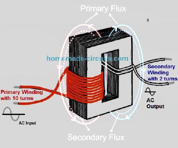
Figure (2)
Whenever the load resistance is connected into the secondary winding, the voltage stimulated into the secondary winding triggers current to circulate in the secondary winding.
This current produces a flux rings around the secondary winding (indicated as dotted lines) that may be as an alternative to the flux field around the primary (Lenz's law).
Consequently, the flux around the secondary winding cancels most of the flux around the primary winding.
With a smaller amount of flux encircling the primary winding, the reverse emf is cut down and more amp is sucked from the supply. The supplementary current in the primary winding releases additional lines of flux, pretty much reestablishing the initial amount of absolute flux lines.
TURNS AND CURRENT RATIOS
The quantity of flux lines produced in a trafo core is proportional to the magnetizing force
(IN AMPERE-TURNS) of the primary and secondary windings.
The ampere-turn (I x N) is indicative of magneto motive force; it can be understood to be the magnetomotive force produced by one ampere of current running in a coil of 1 turn.
The flux which is available in the core of a transformer surrounds together the primary and secondary windings.
Given that the flux is identical for each windings, the ampere-turns in each, primary and secondary winding should always be the very same.
For that reason:
IpNp = IsNs
Where:
IpNp = ampere/turns in the primary winding
IsNs - ampere/turns in the secondary winding
By dividing both sides of the expression by
Ip, we get:
Np/Ns = Is/Ip
since: Es/Ep = Ns/Np
Then: Ep/Es = Np/Ns
Also: Ep/Es = Is/Ip
where
- Ep = voltage applied across primary in volts
- Es = voltage across the secondary in volts
- Ip = current in the primary in Amp
- Is = current in the secondary in Amps
Observe that the equations indicate the ampere ratio to be the inverse of the winding or the turn ratio as well as the voltage ratio.
This implies, a transformer possessing fewer number of turns in the secondary side compared to the primary may step down the voltage, but it would step-up the current. For instance:
A transformer suppose has a 6:1 voltage ratio.
Try to find the current or amps in the secondary side if the current or amp in the primary side is 200 milliamperes.
Suppose
Ep = 6V (as an example)
Es = 1V
Ip = 200mA or 0.2Amps
Is = ?
Answer:
Ep/Es = Is/Ip
Transposing for Is:
Is = EpIp/Es
Substituting:
Is = (6V x 0.2A)/1V
Is = 1.2A
The above scenario addresses that despite the fact that the voltage across the secondary winding is one-sixth the voltage across the primary winding, the amps in the secondary winding is 6 times the amps in the primary winding.
The above equations could very well be viewed from an alternative perspective.
The winding ratio signifies the sum through which the transformer enhances or boosts or reduces the voltage connected to the primary side.
Just to illustrate, suppose if the secondary winding of a transformer has double as much number of turns as the primary winding, the voltage stimulated into the secondary side will probably be twice the voltage across the primary winding.
In case the secondary winding carries one-half the number of turns the primary side, the voltage across the secondary side is going to be one-half the voltage across the primary winding.
Having said that, the winding ratio along with the amp ratio of a transformer comprise an inverse association.
As a result, a 1:2 step-up transformer could have one-half the amp in the secondary side compared to the primary side. A 2:1 step-down transformer can have two times the amp in the secondary winding in relation to the primary side.
Illustration: A transformer with a winding ratio of 1:12 possesses 3 amperes of current in the secondary side. Find out the magnitude of amps in the primary winding?
Given:
Np = 1 turn (for instance)
Ns = 12 turns
Is = 3Amp
Lp = ?
Answer:
Np/Ns = Is/Ip
Substituting:
Ip = (12 turns x 3 Amp)/1 turn
Ip = 36A
Calculating Mutual Inductance
Mutual induction is a process in which one winding goes through an EMF induction due to rate of change current of the adjacent winding leading to an inductive coupling between the winding.
In other words Mutual Inductance is the ratio of the induced emf across one winding to the rate of change of current on the other winding, as expressed in the following formula:
M = emf / di(t) / dt
Phasing in Transformers:
Normally, when we examine transformers, most of us believe that the primary and secondary winding voltage and currents are in phase with each other. However, this may not be always true. In transformers, the relation between the voltage, current phase angle across primary and secondary relies on how these winding are turned around the core. It depends on whether they are both in anticlockwise direction, or clockwise direction or may be one winding is turned clockwise while the other winding anticlockwise.
Let's refer to the following diagrams to understand how the winding orientation affects the phase angle:
In the above example, the winding directions look identical, that is both primary and secondary winding are turned in the clockwise direction. Due to this identical orientation, the phase angle of the output current and voltage is identical to the phase angle of the input current and voltage.
In the second example above, the transformer winding direction can be seen wound with opposite orientation. As can be seen the the primary seems to be the clockwise direction while the secondary is wound in anticlockwise. Due to this opposite winding orientation, the phase angle between the two winding is 180 degrees apart, and the induced secondary output shows an out of phase current and voltage response.
Dot Notation and Dot Convention
In order to avoid confusions, Dot notation or Dot convention is employed to represent the winding orientation of a transformer. This enables the user to understand the input and output phase angle specifications, whether the primary and secondary winding are in phase or out of phase.
Dot convention is implemented by dot marks across the winding start point, indicating whether the winding are in phase or out of phase with the each other.
The following transformer schematic carries a dot convention denotation, and it signifies that the primary and the secondary of the transformer are in phase with each other.
Dot notation used in the illustration below shows the DOTs placed across the opposite points of the primary and the secondary winding. This indicates that the winding orientation of the two sides are not the same and therefore the phase angle across the two winding will be 180 degrees out of phase when an AC input is applied on one of the winding.
Losses in a Real Transformer
The calculations and formulas considered in the above paragraphs were based on an ideal transformer. However in real world, and for a real transformer, the scenario may be a lot different.
You will find that in an ideal design the following fundamental linear factors of real transformers will be ignored:
(a) Many types of Core losses, together known as magnetizing current losses, that may include the following types of losses:
- Hysteresis losses: this is caused due to nonlinear influences of the magnetic flux on the core of the transformer.
- Eddy current losses: This loss is generated due the phenomenon called joule heating in the transformer core. It is proportional to the square of the voltage applied to the primary of the transformer.
(b) In contrast to the the ideal transformer, the resistance of the winding in a real transformer can never have a zero resistance. Meaning the winding will eventually have some resistance and inductances associated with them.
- Joule losses: As explained above, The resistance generated across the winding terminals gives rise to Joule losses.
- Leakage flux: We know that transformers heavily depend on magnetic induction across their winding. However, since the winding are built on a common single core, magnetic flux show a tendency of leaking across the winding via the core. This gives rise to an impedance called primary/secondary reactive impedance, which contributes to the losses of the transformer.
(c) Since a transformer is also a kind of inductor, it is also affected by phenomenon such as parasitic capacitance and self-resonance, on account of electric field distribution. These parasitic capacitance usually can be in 3 different forms as given below:
- Capacitance generated between the turns one above the other inside a single layer;
- Capacitance generated across two or more adjoining layers;
- Capacitance created between the transformer core and the winding layer(s) lying adjacent to the core;
Conclusion
From the above discussion, we can understand that in practical applications calculating a transformer, especially an iron core transformer may not be as simple as an ideal transformer would be.
To get the most accurate results for the winding data we may have to consider many factors such as: flux density, core area, core size, tongue width, window area, core material type etc.
You can learn more about all these calculations under this post:


Questions & Answers
Hi Mr Swagatam;
I was confused on writing this under the correct header, since my yj61/200 model fan motor has the fan and motor and also the tarnsformer (P.S.: there are pictures at the media /Shenzhen Motor and transformer coil value is about 74 Ohm ). This motor specs are 120AC 40W and 60H. I will try to run this fan motor with the 220V AC and 50 Hz. So by assuming the current is about 200mA, is it possible to run this fan motor by adding the serial 500 Ohm 1W resistor? Or for instant I can use the 5K pot to test it after your confirmation.
Hi Suat,
According to me you can simply use a 4uF/400V PPC capacitor in series with the fan supply and operate it with 220V AC. A resistor can heat up a lot, so a capacitor is more preferable…
Thank you indeed Swagatam, sorry since after sending the message I have understood that I had made a totally mistake on calculation the values. I will try your valuable advise and is it possible to also use a bulb in series as an other remedy?
Best Wishes
No problem Suat!
Bulb will work but will waste power, so capacitor appears to be the best choice.
I wonder if you can comment on the impact of core cross sectional area in a 3-phase transformer where all coils are wound on a common ie “EI” type core? In particular, I’m wondering about winding a 3-phase step down transformer for a VFD. The center stack of a microwave transformer is typically bigger than the surrounding lamination arms. Can this be compensated for in the coil windings? Does it need to be corrected for? Thanks Swagatam
Doug
Hi Doug, sorry, presently I do not have sufficient knowledge in this subject so it can be difficult for me to solve and answer to your query.
Hi Swagatam;
When a transformer specs is input 220 AC and output 12 V DC and load is a bulb 12 V 5 A .
So then it is possible to say that transformer consumes about AC 0,25 A since source / input is 220 AC?
Best Regards
(P.S.: I ask because that I have no AC ampermeter)
Hi Suat, yes that’s absolutely correct!
Hi Swagatam;
I have seen a video about current booster at youtube. The parts in the boost circuit are 2 pcs of RU6888 mosfets and 1 pc of 100 uH coil and 2 pcs of 0,33 mF 1200 V capacitors parallel connected and a core dismantled from a crt tv high voltage flyback transformer.
I have the questions are:
It is really possible to boost the current as we boost the voltage? In the other word, it is possible to gain more current than we have the input transformer current capacity? Let’s say we have the transformer which is 220 AC to DC 12 V 5 A then it is possible to gain 7 Ampere by using the current booster circuit above mentioned. Best Regards
P.S.: In case you request I can mention youtube video page code.
Hi Suat,
That is impossible! If you increase current then voltage has to go down and vice versa. To be precise, the output power can never be higher than the input power!
So if a 12V 5 A transformer is used, you can never boost it to 12 V 7 Amps. If you boost it to 7 amps then the voltage has to drop to 8.57 V.
Hi Swagatam;
My scrap transformer laminated core plates size is 10,5 cm x 8 cm x 6 cm and the coil dimension is 7 cm x 10 cm.
I think that one is pull-out from microwave oven.
As to input / output legs of the two coils, there are 3 legs of each coil. And the resistor measurement values:
Coil one (I think wire dia. is about 0,7 mm) ohm value between blue and white wire is 0,6 ohm
And blue and red / white and red values are 2,4 ohm.
Coil 2 (I think its wire dia. is about 0,25 mm and that is primer coil) and one wire leg output is soldered to the core.
All three wires are orange insulated (namely same color)
Between Wire 1 and Wire 2 ohm value is 0,7 ohm.
Wire 3 has no contact with Wire 1 and Wire 2 but there are about 110 ohm between the wire 3 and the wire that is soldered to the core.
So please advise, if the above info are enough to comment, it is possible to say that it is not out of order or how I can test it and it is possible to estimate its approximately current / ampere capacity? Best Regards
Hi Suat,
Yes, the transformer looks OK to me since there are continuity across the relevant winding taps.
However it can be difficult to find out the voltage specs of the winding unless we have one set of wires whose voltage rating is known. For example we have to find out which are the 220 V wires, then we can feed 220V to these wires and measure the voltage outputs across the other wires.
To randomly find out the 220V wires you can feed 220V AC across the wires sets randomly using a 40 watt or 25 watt bulb in series. As long as the bulb illuminates will indicate that the wires are not rated for 220V. As soon as you find the bulb not illuminating for a particular winding, then you can assume those wires to be the 220V wires.
You can keep the 220V AC connected to those wires through the bulb and start measuring the voltage output from the remaining wire taps to know the exact output values.
Hi Swagatam;
I found a transformer from scrap shop. Secondary output is AC 7.8 V after rectified and filtered by 2200 C then output is DC 22 V. So to make the 12 V Fan run I can use that 22 V DC output directly to the fan or should use 7812? Best Regards
Hi Suat,
You must use a 7812 IC so that the fan does go through an over voltage and over current condition.
Hi Swagatam;
I have been seeing the regulator circuits 220 AC to 12 DC without transformer. There is a 105K 400 V capacitor at the AC side and diode rectifier and output capacitor about 220 mF. May have your opinion about that. Best regards
Hi Suat, the 105 high voltage input works like a current limiter and restricts the input 220V current to a 50 mA
4 Simple Transformerless Power Supply Circuits Explained
siwewe 100w inwveter circit diagrams
Hello dear swagatam
I hope that you are fine and healthy
Thank you so much again for your detailed response which once again made me truly really happy. you are right Sir. Three pairs of windings are isolated from each other internally. I connected one blue and one white wires to each other and got 24 volts from the other end of these two wires and then added one yellow wire to the other white wire and the result between the two ends of blue and yellow ones was 32 volts which is excellent and I got my answer.
I will never forget your kindness; Sir
With best regards and wishes
Nassim
That’s great Nassim, I am glad you could solve the problem so quickly. Wish you all the best, and keep up the good work.
Hi dear and lovely swagatam
Hello and thank you so much for so soon replying my question which made me really very glad. I am very sorry for not well explaining the status of wires. It has 6 wires in 3 colors: 2 yellow wires are 6 volts; 2 white colors are 9 volts: and 2 blue ones are 12 volts. I guess there is nor 0 tap wire and I can not get 27 volts. Am I right?
thank you dear again for your response
very truly yours
Nassim
You are welcome Nassim, If you are unable to get the total sum of 27 V at the ends of any two wires, then most probably the various winding are isolated from each other internally. In that case you can use your multimeter and set it at the diode range and start checking which two adjacent wires do not have any continuity.
If you find nearby sets of wires which do not have any continuity, you can join those wires and then check the total voltage across the wire ends, and in this way you can achieve the total 27 v output with some experimentation. Make sure to attach a 100 watt or 60 watt wire in series with one of the mains wires of the transformer just to be safe in case something goes wrong.
Hello Mr Swagatam
I hope that you are fine and healthy
I have a 220 V transformer which it’s secondary voltages are: 12, 9, and 6 volts AC. would you please tell me if it is possible to have 27 volts by adding these three to each other and how?
Thank you in advance for your reply
Truly yours
Nassim
Thank you Nassim, I am good!
The voltage taps that you have mentioned should have a corresponding 0 V tap reference, in other words you must have 4 wires in all: 0 to 12, 12 to 9 and 9 to 6….so if you measure the voltage across the end wires, meaning between 0 V and the 6V taps you should be able to get the required 27 V
Good day sir, if I buy a factory wound trafo of 12-0-12v,and I use rectifier, for DC output I will get around 16.9v using center tap. How can I get 14.1v to charge 12v battery from the trafo. Thanks
Hi Adyemi, you will need a voltage regulator for limiting the voltage to 14.1V.