This one transistor cheap battery charger circuit is designed to automatically switch OFF the supply to the battery as soon as the battery has reached its full charge level.
A very simple single transistor automatic battery charger circuit is I have I have explained in this article, which uses just a single transistor for the voltage detection as well as for automatically disconnecting the battery from the supply when it gets fully charged.
Circuit Operation
As shown in the diagram we can see a straightforward configuration where a solitary transistor is connected in it’s standard operating mode. The circuit functioning may be understood with the help of the following points:
Considering the battery to be charged is a 12 volt battery, we know that it is advised to charge the battery until it reaches between 13.9V to 14.3 volts.
The transistor base voltage is adjusted using the preset P1, such that the transistor just conducts and operates the relay at around 14 volts.
How to Adjust the Cut of Thresholds
This adjustment becomes the high voltage trip point of the circuit and is used to switch OFF the charging voltage to the battery when it gets fully charged or its voltage reaches around 14 volts.
The lower trip point of the circuit cannot be adjusted as this circuit is too simple and does not incorporate the low voltage detection feature.
However the transistor is itself equipped with a switch OFF feature in case its base voltage becomes too low.
Typically a general purpose transistor like the one which is shown (BC547) when adjusted to switch ON at 14 volts may have the lower threshold of around 10 volts, when it might get just switched OFF.
This wide voltage difference between the high set threshold and the lower natural threshold is because of the involved big hysteresis with the design. This acts like a natural hysteresis in the design.
The lower threshold of 10 volts is dangerously low and we cannot wait for the circuit to restart the charging process until the battery voltage falls to this dangerous 10 volts level.
Allowing the battery to discharge down to 10 volts can make the battery flat permanently and reduce its life. . Therefore to eliminate this issue the circuit needed to somehow reduce the hysteresis level. This is done by introducing a couple of diodes at the emitter of the transistor.
We know that normally a 1N4007 diodes would drop around 0.7 volts across it and two if them would make a total of 1.4 volts. By inserting the two diodes in series with the emitter of the transistor, we force the transistor to switch off 1.4 V earlier than its normal specified limit of 10 volts.
Therefore now the lower operating threshold of the circuit becomes 10 + 1.4 = 11.4 volts, which may be considered just OK for the battery and for the automatic restart of the charging process.
Having both the thresholds updated as per the standard charging requirements, we now have an automatic automotive battery charger that’s not only cheap to build but also smart enough to take care of the battery charge conditions very efficiently.
Circuit Diagram
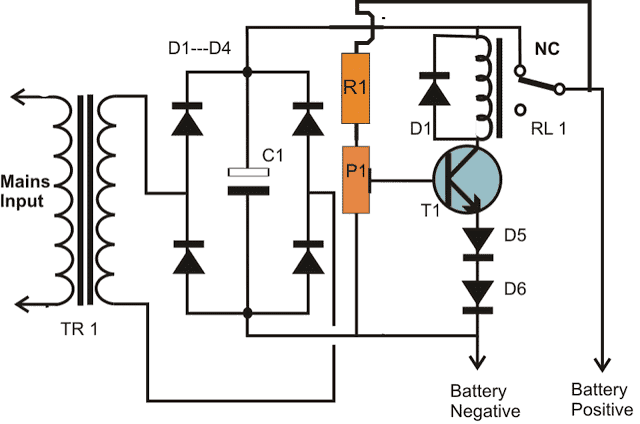
Parts List for the proposed one transistor automatic battery charger circuit
R1 = 4K7 =1
P1 = 10 K preset =1
T1 = BC547B = 1
Relay = 12 V, 400 Ω, SPDT = 1
TR1 = 0 - 14V, current 1/10th of the battery Ah = 1
Bridge diodes = 1N5408 = 4
Emitter diodes = 1N4007 = 2
C1 = Electrolytic capacitor100 µF / 25 V = 1
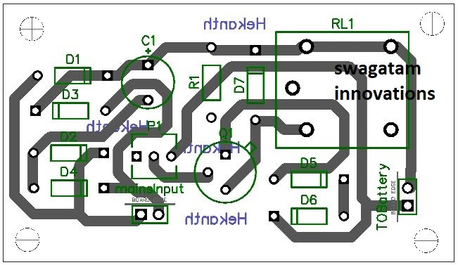
PCB Design
How to Calculate the Components
Transformer Output Voltage
The transformer (TR1) steps down the mains input to a lower AC voltage for rectification.
Let VAC be the secondary RMS voltage of the transformer.
Peak voltage after rectification:
Vpeak = VAC × √2
Rectifier and Filtering
The bridge rectifier (D1 to D4) converts AC to pulsating DC.
The capacitor C1 smooths the rectified DC voltage.
The ripple voltage (Vripple) can be calculated as:
Vripple = Iload / (f × C1)
- Where:
- Iload = Load current (charging current)
- f = Mains frequency (typically 50Hz or 60Hz)
- C1 = Filter capacitor value in Farads
Base Resistor and Potentiometer (R1 and P1)
R1 and P1 form a voltage divider to bias the transistor (T1).
Voltage across the transistor base-emitter junction (VBE) controls the transistors conduction:
VBE = (Vout × R1) / (R1 + P1)
Where Vout is the output voltage from the rectifier.
You must Adjust P1 to set the battery cut-off voltage. The transistor will conduct when:
VBE ≥ 0.7V (for silicon transistors)
Relay Activation
The relay (RL1) will be activated when the transistor T1 conducts completing the circuit.
Relay coil current:
Irelay = (Vout - VCE(sat)) / Rrelay
- Where:
- Vout = Output voltage
- VCE(sat) = Saturation voltage of the transistor (typically ~0.2V)
- Rrelay = Resistance of the relay coil
Diodes (D5 and D6)
D5 and D6 will provide the reverse voltage protection and prevent over-discharge of the battery.
Voltage drop across these diodes:
Vdrop = n × Vf
- Where:
- n = Number of diodes (2 in this case)
- Vf = Forward voltage drop of each diode (typically 0.7V for silicon diodes)
Battery Charging Current
Charging current will depend on the difference between the charging voltage (Vch) and the battery voltage (Vbat) and the resistance in the circuit:
Icharge = (Vch - Vbat) / Rseries
Where Rseries is the series resistance which may include internal resistance of the battery and circuit wiring.
Relay Cut-Off
The relay will disconnect the battery when the battery voltage exceeds a threshold set by P1 and R1.
Cut-off voltage should be approximately:
Vcut-off = VBE + VD5 + VD6
Practical Adjustments
You must Fine-tune P1 to set the desired battery cut-off voltage based on the battery type and specifications.
You must Select the R1 and the C1 to ensure proper filtering and biasing.
Practical Solved Example for a 12V 7 Ah Lead Acid Battery
Let us assume we want to charge a 12V 7 Ah lead acid battery with auto cut and self restoration. Then we can calculate the above parameters in the following manner:
Calculating the Transformer Output Voltage
To charge the 12V battery up to 14V, the rectifier's output voltage needs to exceed this voltage after accounting for diode drops and ripple.
Assuming a full-wave rectifier with two diodes in series:
Total diode drop = 2 × 0.7V = 1.4V
Required minimum peak voltage = 14V + 1.4V = 15.4V
RMS voltage of the transformer secondary:
VAC = Vpeak / √2 = 15.4 / 1.414 ≈ 10.9V RMS
Choose a transformer with a secondary RMS voltage of 12V to ensure some margin.
Calculating the Filter Capacitor (C1)
The filter capacitor smooths the rectified DC. Let the load current (Iload) be the charging current.
For lead-acid batteries, a safe charging current is around 10% of the battery capacity:
Iload = 0.1 × 7 Ah = 0.7 A
Assuming a mains frequency of 50Hz, the ripple voltage should be small (e.g., 1V). The required capacitance is:
C1 = Iload / (f × Vripple) = 0.7 / (50 × 1) = 0.014 F = 14,000 μF
Use a capacitor with a value of 14,000 μF (or higher) and a voltage rating above the rectified voltage (e.g., 25V).
Setting the Cut-Off Voltage (P1 and R1)
The cut-off voltage is set to 14V. The transistor T1 turns on when its base-emitter voltage VBE reaches ~0.7V.
Voltage across the R1-P1 divider must match this threshold:
VBE = (Vout × R1) / (R1 + P1) = 0.7 V
Now let us Rearrange the terms to calculate the ratio of R1 and P1:
R1 / (R1 + P1) = 0.7 / 14 = 0.05
Let R1 = 1 kΩ, then P1 = 19 kΩ.
Use a 1kΩ resistor for R1 and a 20kΩ potentiometer for P1 to allow fine adjustment of the cut-off voltage.
Calculating the Relay Specifications
Relay must be able handle the charging current,, and operate at the rectified voltage.
Coil voltage: Vcoil = Vout - VCE(sat) ≈ 14 - 0.2 = 13.8V
Coil resistance: We should Choose a relay with a coil resistance such that:
Irelay = Vcoil / Rrelay
Ensure that Irelay matches the transistors current-handling capability (typically < 1A for small transistors).
Calculating the Charging Current
With a 0.7A charging current and the series resistance in the circuit we will calculate the total resistance needed as:
Rseries = (Vch - Vbat) / Icharge = (14 - 12) / 0.7 ≈ 2.86 Ω
Use a resistor close to 2.7Ω or 3Ω, rated for power dissipation:
P = Icharge² × Rseries = 0.7² × 2.86 ≈ 1.4 W
We must Choose a resistor rated for at least 2W.
Finalized, Component Values:
- Transformer: 12V RMS secondary, capable of 1A or more.
- Filter Capacitor (C1): 14,000 μF, 25V.
- Base Resistor (R1): 1kΩ.
- Potentiometer (P1): 20kΩ.
- Series Resistor (Rseries): 2.7Ω, 2W.
- Relay: 12V coil voltage, capable of switching 1A or more.
Single Transistor Battery Charger Circuit with Auto Cut-off
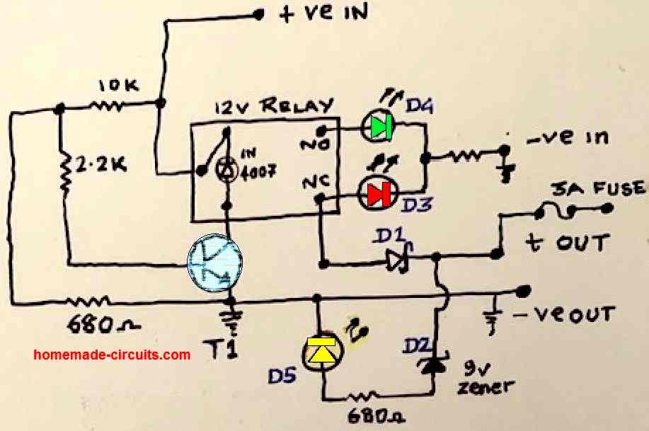
In this article I have explained a very simple automatic battery charger circuit using a single transistor and a relay as the main components. Despite being extremely simple, the design exhibits an auto cut-off feature when the battery reaches full charge level. The circuit also has a 3-LED indicator for indicating the various charging stages of the battery.
Parts List
- Resistors are all 1/4 watt 5%
- 10 K = 1no
- 680 Ohms = 3nos (2 resistors connected with the LEDs)
- 2.2 K = 1no
- Semiconductors
- 1N4007 = 1no
- 9 V 1/2 W zener diodeD2 = 1no
- D1 Schottky diode SR360/SR560 = 1no
- T1 Transistor can be BC547, BC548/2N3904/2N2222 = 1no
- D3 RED LED 5mm 20 mA = 1no
- D4 Green LED 5mm 20 mA = 1no
- D5 Yellow LED 5mm 20 mA = 1no
- Relay 12V 400 mA = 1no
How the Circuit Works
Referring to the above single transistor automatic battery charger circuit, the working details can be understood with the following points:
Initially, the discharged battery which needs to be charged is connected across +OUT and the ground -Ve OUT of the circuit.
The +OUT of the charger circuit goes to the positive terminal of the battery via the 3 amp fuse.
The GND line of the -VE OUT goes to the battery negative terminal.
After this, the circuit is powered through a 13.5 V regulated DC supply. The positive is connected to the +Ve IN point, and the negative is connected to the - Ve in point.
The above DC enters the circuit and passes through the pole of the relay and reaches the N/C contact of the relay.
From the N/C contact of the relay, the 13.5 V reaches the battery (+) terminal D1 and the 3 amp fuse.
Let's assume the voltage of the discharged battery is 11 V. The 13.5 V of the input supply is now dragged down to the 11 V value.
The battery now begins charging.
The RED LED gets the operating voltage via the relay N/C contact and illuminates, indicating that the battery is charging.
The calculated values of the resistive divider (10 K and 680 Ohms) at the base of T1 ensures that T1 remains switched OFF as long as the battery is charging and its terminal voltage is below 13.5 V.
As the battery charges, at some point of time its terminal voltage reaches an intermediate higher value. This illuminates the yellow LED via D2, indicating the charging status of the battery.
Finally, after many hours of charging, the battery voltage reaches the set full charge level of 13.5 V. When this happens, the base potential of transistor T1 becomes sufficiently high forcing the transistor to conduct.
The transistor now switches ON and activates the relay, whose contacts now changeover from N/C to N/O.
This cuts off the supply to the battery and the charging of the battery is inhibited. In this way the automatic battery cut-off is executed when the battery reaches the set full charge level.
The green LED connected with the N/O contact of the relay lights up indicating that the battery is now fully charged, and the charging has been cut off.
Notes:
The above explained single transistor 12 V automatic battery charger circuit was tested and found to be working perfectly OK.
The battery used for the testing was a 12 V Lead Acid Battery
Full charge level cut off level was set to 13.5 V, and the input DC supply was 14.5 V.
Since the full charge cut off level is determined by the 10 K and the 680 ohm resistors at the base of the transistor, you can adjust these values to change the full charge cut off level to any other appropriate value.
Remember, the discharge battery must be always connected first before powering the circuit. Otherwise the relay will switch ON and move to the N/O contacts and then connecting the battery will keep the battery cut off.
Prototype Images
The first image below shows the internal construction of the single transistor automatic battery charger circuit. We can clearly see the complete assembly consisting of the resistors, transistor, relay, diodes, and the LEDs.
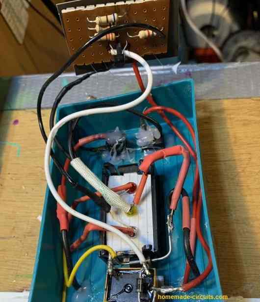
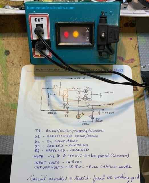
The next image below shows the testing procedure of the circuit, which is charging an attached battery. The RED and the Yellow LEDs are switched ON, indicating the ongoing charging process, and the battery has reached an intermediate charging stage, approximately at around 13 V.
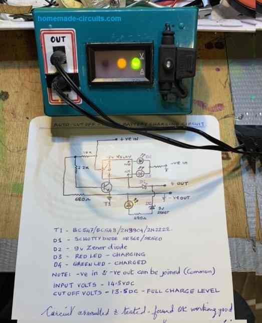
The next image below shows the battery is fully charged and the relay has cut off the charging supply to the battery. The green and yellow LEDs indicate the fully charged status of the battery.
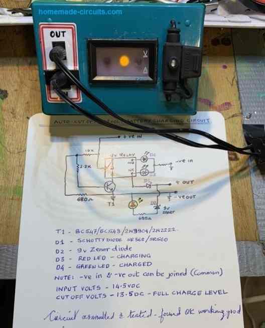
The last image below shows SoC status of the battery, indicated by the illuminated yellow LED. This happens when the power to the circuit is switched off and the battery is still connected with the circuit.


Questions & Answers
Hello Mr.Swagatam. I think this simple “One Transistor Automatic Battery Charging Circuit” just might work in my solar system. I would use the solar panels to supply the power instead of the mains transformer and bridge shown. My question is since the solar input could vary from no-load of around 20VDC to a load voltage of around 12VDC would this interfere with normal operation of the circuit or would I need to add some some sort of regulator such as a zener diode into the circuit? Thanks for your suggestions.
Thanks Paul,
This circuit is cheap and simple, however please do not expect it to be accurate, although the accuracy can be increased by using a fixed resistor in place of the preset.
The circuit should be able to find and sense the varying voltage therefore a regulator cannot be used.
However, if the solar panel voltage drops below the battery full charge level then the battery cannot charge optimally and the circuit won’t cut off.
Make sure to add a 1000uF capacitor right across the relay coil.
OK Thanks for the additional information. The circuit is simple enough to put together rather quickly so I’ll start gathering the components. Will update as things progress. Thanks for your time and interest in this project.
No problem Paul, all the best to you.
Let me know if you have any further issues.
Hello sir( happy republic day) … My. Question is that sir. I have 13-0-13 4a transformer and i make battery charger from this transformer by using 4 IN 5408 DIDODE, 4700uf/35v and the dc voltage come from that is 18v how to simply adjust 14v 1A from given cricuit diagram with their autocutt function… Please suggest me sir…
Happy Republic Day Apurva.
For setting the circuit, apply 14V to the circuit from an external power supply, and then adjust the preset such that the relay just clicks. That’s all, your circuit is all set now..
After this you can connect the discharged battery and switch ON the transformer, once the battery reaches 14V the relay will cut off.
Remember you will have to connect the battery first and then switch ON the transformer.
And you must NOT use 4 amp for a 7Ah battery. If your battery is a 7Ah, use a 1 amp or 500mA transformer.
Or alternatively, you can connect a 12V motorcycle side indicator bulb in series with your battery positive for your existing 18V 4 amp output. The lamp will take care of the current.
For ur last paragraph where u write.. (alternatively, you can connect a 12V motorcycle side indicator bulb in series with your battery positive for your existing 18V 4 amp output. The lamp will take care of the current).. It means to say i can use this 4amp transformer for charging the 12v 7ah battery before connecting 12v bike bulb for reducing the current… To the dc 18v power coming from the Bridge rectifier..
yes that’s right. The bulb should be 12V 10 watt as shown below. Use only one in series:
After connecting it then how much amp will be reduced.. Sir..
1 amp…use only one bulb!
Thank you for the great thing you are doing in this site.
please I need a battery charger circuit with a cut off circuit. in this case, let is function like some phones like Infinix. when it’s charging, the LED will be ON, if it full, the LED will turn Off. it will have only one LED bulb, and not two. It could be Red or White.
when it is charging, the light will be on, when it is full the led will turn Off, instead of changing from Red to Green.
thank you sir.
Hi Basil,
In that case you can try the last circuit explained in the following article.
https://www.homemade-circuits.com/self-regulating-lead-acid-battery/
Let me know if you have any further questions…
Are the two capacitors electrolytic or normal capacitors? I’m going to get the components today
They should be electrolytic type.
Thanks and voltage ratings?
any value that may be equal or higher than twice the supply voltage
Hey I added the transformer of greater rating and circuit worked but now I see that my transistor has blown aka Base emitter is open… If I were to place a resistor in series with the Base would it prevent damage to the transitor? also the relay buzzes even with a flywheel diode
Best regards Adrian Sassin
Hi, the transistor can never get damaged because R1 is already present. R1 will restrict the current in case the preset adjustment is shorted accidentally.
The transistor can possibly burn if the flywheel diode is not good. You can try changing the diode with a good quality 1N4007 diode.
To stop buzzing you could try adding a 10uF capacitor across base/emitter of the transistor and and also a 100uF capacitor parallel to the relay coil.
Greetings I used a 15V 1A transformer to charge the battery for the circuit but when I charge the circuit noting I get 0.4 mA on the Dc side and my battery starts to make hissing noise… It cuts off at 13.7 but after and hour or two it goes to 13.4V what is the reason for this hissing and the discharge and what can I do to rectify the problem? I’m using this circuit in conjunction with and emergency light… my battery is a 12V 7ah
Hi Adrian, that looks quite strange, because at 1 amp a 7Ah battery will never hiss. Try adding a current control stage using the following circuit and set the current to 500mA:
https://www.homemade-circuits.com/universal-high-watt-led-current-limiter/
If still you hear the weird sound then the problem could be in your battery.
the one transistor cut off circuit explained above may not be very accurate since the preset adjustment could deviate slightly overtime, giving rise to errors, you can try using fixed resistors instead of the perset to get reasonably consistent cut off response from the circuit
Hey I wanted to ask I’m getting 0.45mA when the battery chargers.. How can I increase current flow to 0.7A to change lead acid 12V battery 7ah… Transformer I’m using is 15V 1A and is quite warm after a few hours
Regards Adrian
Hey Adrian, your transformer may not be actually rated at 1 amp, because most transformers usually print slightly higher rating than its actual capacity. Try some other slightly higher rated transformer, may be upto 2 amps and see the response.
If still the current does not increase then your could be having problems.
Circuito não esta funcionando….tem um erro no R-1 e tambem no C-1 negativo, …. estão sem coneção ( Design do PCB ) só funcionou depois de fazer mudanças
Obrigado por apontar o erro no design do PCB, ele foi projetado por uma pessoa externa, não eu, mas de qualquer maneira, estou feliz que você possa corrigi-lo e fazer com que ele funcione para você
Greetings if I use a 12V 7ah lead acid battery… What will the charging current be that will charge the battery?
Hi Adrian, it should ideally 0.7 amps, but 1 amp will be just fine!
Hi I wanted to ask.. The Base voltage I measured when it starts conducting (when charger cuts off) is 1.45V? why is this voltage so high? Regards Adrian Sassin
Hi, it is because of the combined voltage drops from the two emitter diodes and also the transistor itself
But so far I only connected on emitter diode not two
so it is 0.7V for the diode and 0.7V for the transistor, resulting in 1.4V
sir can I use this circuit to charge my 60ah battery.. if yes. what are the changes required in the circuit
Manish, you can do it just make sure to select a relay with contacts rated at 10 amp
Sir,
I built a battry charger using a step down tranfo and this circuit. The challanges am facing is that, If our Main AC is above or below 220v the DC output is varying either above 13v or below 11v and this may damage my battery.
So an Idea came to my mind and I changed transfo with a UPS tranfo that has 175v, 195v, 220v and 250v primary and 7v-0-7v secodary and am using outer taps that gave 14v to charge battery.
I used four (4) switches, 1st switch From Main to 250v of tranfo, 2nd swtch from main to 220v of transfo, 3rd swtch from main to 195v of transfo and the last one to 175v, If the Main AC power drop below 220 am switching either 195 or 175 switch so that the output will be okey for charging the battery and if the Main is 220, I off all the switch and On 220v switch. I am doing the same, to others depending on the Main AC voltage reads on the analong metre. At that moment, I realised that, since our Main power is either above 220v for many hours and sometime dropped below 220v for many hours, then I have to introduce a circuit that can do this changes of Main AC input to my tranfo automatically so that my battry will charge and remain safe. I need your help.
Thank you Sir.
Aminu, if your step down trafo is 0-12V rated, and if you use a bridge rectifier with a high value filter capacitor, that will be enough to raise its output 14.5V at 220V.
Or alternatively you can use a 0-24V trafo and use an LM338 regulator to regulate the output at 14V
If you are thinking of employing a voltage stabilizer circuit that will be an overkill..
Sir I did it, and it's working fine.
The transfor is 12v 5A
The bridge rectifier is 10A
The Diode i.e +recitifier to battery+ is 6A 400V
And the Caps is 4700uf 25v.
The output I got is around 14v to 16v.
Now, How can I set the above circuit for autor cut-up?
Thank you very much for your kind help.
Aninu, diodes should not be connected in parallel. the heatdink method will be more effective
Sir, can I connect two or three 6A diodes, in parallel, to double the current?
Okey, thank you very much sir.
I will try this.
that means MBR20100CT cannot be use, which is very simple to clamp on the heatsink?
Aminu, you can clamp the diode with an aluminum heatsink for cooling it. you can innovate the clamping method by some thinking
Good Day Sir,
I am done with this battery charging circuit. But the diode you suggested me to use between rectified positive power from transfo to the positive to battery is getting hot. And it is a 6A diode. I tried finding higher current in the market but I didn't get one.
So, can I use MBR20100CT, which is 20A 100v three pin diode in form of transistor?
If yes, I need your help on how to coonect it.
Thanks very much Sir.
you can use any form of battery, lead acid is not compulsory, but the charging current can be different for different types of battery, for example if a Li-ion batt is used then the charging current could be as high as its AH value, but for lead acid it is recommended to be 1/10th of its AH
thanks for the reply sir.
So, do you means, I cannot charge other battery type than lead asid (as you have suggested in last reply) with is circuit?
…while practically charging the battery make sure the discharged battery is connected first and then power is switched On
the power supply current must be 1/10th of the lead acid battery AH
Aminu, first adjust the preset such that the slider completely touches the ground side of the preset.
now apply the supply voltage to the circuit….now very carefully and skillfully adjust the preset upwards until the relay just switches ON.
that's all your circuit is set.
Sir, KBPC2504 It's a 25A diode brigde.
Aminu, connect a 2200uF/25V filter capacitor and then check the response.
also check whether the bridge is getting warm or not, without load….if it is then your connections could be wrong.
Thank you Sir.
If I got you right, connecting a diode from a 12v tranfor to a positive of 12v battery can charge the battery to 14v?
Hi Aminu, what is KBPC2504, please specify….
Okey Sir.
Sir, Can I use KBL406 diode bridge and 12v 5A transfo with this circuit to charge a car battery. i.e 12v 50A battery?
Again, I had once connected KBPC2504 to a 14.2v transfo and the voltage at + and – output of the tranfo at diode dropped to around 11v. What mades the voltage dropped to 11v?
Thanks for the help you are offering us Sir.
Aminu, the diode needs to be connected after the bridge/capacitor network, if you use only the diode without the bridge then the output voltage will not reach even 13V
Okey Sir.
Sir, could you help me on how to rectify 12v to 14v? And, How/Where do I connect the 60ohm resistor and of what watts?
Thanks for the help.
charger(+)—–>|——-battery(+)
1n5408 or 6A4
connect a diode instead, in between with the charger positive and battery positive, this will drop 0.7V and never allow the battery to reach 14.4V or over
Thank you Sir.
Sir, If am using 12v tranfor, is there any harm to battery if it is fully charged?
So that, no need to use battery charge circuit for battery full cut off.
thanks one again.
12V after rectification/filtration will become almost 14.5V…although it won't harm the battery much, it is not recommended to keep the battery connected with a 14.5V supply after it is fully charged. use a low ohm resistor around 60 ohm in series this will allow you to keep the supply connected permanently.
Sir,
Using the above circuit, can I replace the relay with DTDP, so that, I can configure it to off the charger from main power when the battery is fully charged.
And, If I apply transfo with any volts above 14 (as specify) will it damage the battery? let say the transfro volt is 18 to 20 while the current remain 1/10th Ah of the battery.
Thankd you Sir.
Aminu, you can do it but you may to incorporate an ON/OFF push-switch in parallel with the contacts which is wired with the mains, this push-switch will be used to switch ON the circuit initially.
18V will damage the battery once it's fully charged even if the current is 1/10th…so make sure the voltage is not above 14.5V
Sir, could I use this circuit for 110ah 110ah 110ah 12 volt D.C. battery?
Hi Raja, yes you can connect the mentioned battery by suitably upgrading the relay to a 20amp relay and by replacing the BC547 with a 2N2222
Hi,
Please share the 3 and 6 volt auto cut battery charger circuit.
Regards
DEV
you can try the following design:
https://www.homemade-circuits.com/2013/12/usb-automatic-li-ion-battery-charger.html
no there's no proper place to add LED indicators in this cirucit…
hello, try adding a few more diodes with the existing emitter diodes D5, D6 and see if it makes any difference..
Hi, replace the relay coil with a 1K resistor…connect the gate of the mosfet with the collector of the BC547….connect the source with the ground, and connect the battery across the positive supply and the drain of the mosfet
Can you design a circuit to automatically charger 3 batteries at a times assuming that not all the batteries have thebsane amount of charge so they should be able to shut off individually when they reach full charge
simply make 3 separate chargers and connect them separately to the batteries…I have discussed many automatic 741 battery charger circuits which can be replicated 3 times for the desired results.
14 volt transfirmar not available any market please help…..
14.3V
What is a full charge 12 volt battery voltage
use a 2 amp 12V transformer, bridge using 1N5408 diodes and capacitor 2200uF/25V
Not work and my battery is 12 volt 12 ah so what is capable AmpeR to fast and safe battery chRge and wich type value of using bride center capasitor
use 0-12V bridge rectification and filtration will finally produce 14V
sir
this circuit is work very well for me i have tried a lot of 12v charger circuit but if i conpair this is the best for me thank you ok,but sir i want to put led where it should be put to indicate the battery is full charge? thank you.
OK thanks! for a full charge indication you can connect a red LED across the relay N/O contact and the negative of the circuit via a 1K resistor.
sir please i don't really know the AH i asked the seller man he said it American gell battery it don't have AH but it a 21plate battery.
your battery could be drawing large current beyond the capacity of the diodes, increase the diode rating to say 10amps each or more.
sir
please i build this circuit but when i it start charging the rectifier diode got hot almost damage if i didn't switch off,i used 1n5399diode same problem sir i have used three type of rectifier diode but not succeeded sir please any help? thank you.
daniel, what's the battery AH??
sir please can you show me boost circuit using IC555 to generate 28V if you have designed one.thank you
you can try the one shown in the following article:
https://www.homemade-circuits.com/2012/09/led-emergency-light-circuit-using-boost.html
sir please i have two 12v batt 200AH and i want to use 12v charger circuit to charge the two of them but sir i want ask you that if series the two 12v batt 200AH which is 24v batt i have automatic 12v charger so i want to use it charge this 12v 200AH,i have series them 24v so sir im going to send you that 12v automatic circuit please publish it for me so that i can use it to charge my 24v batt 400AH thank you
you will need to make a boost circuit using IC555 to generate 28V and use it to charge the series 24V battery.
you cannot use a 12v charger to charge the series connection
sir please to set btt cut off using variable power supply it plenty difficult for me so i want you to explain it simply for me to understanding if i use variable power supply do i have to remove the transformer from the bridge rectifier and connect variable power supply to the bridge rectifier and remove after set and connect the former or not that way? thank you.
you can keep the transformer connected but do not plug it in to mains.
now you can use a variable power supply whose output must be connected to the circuit's positive and negative terminals directly.
After this the required voltage may be fed to the circuit and the preset adjusted for setting the desired cut off thresholds.
ok sir thank you for accepted my request my prayer is that god will give you strewth than you once again im looking forward.
i have published it, you can see it here:
https://www.homemade-circuits.com/2014/01/extracting-single-phase-voltage-from.html
hi sir please i need something i been searching everywhere but not avail so please im appealing to you if you can do it for me, this is special request,that thing is in my country we have 3phace meter and single phase meter so if you use single phase meter you will get one power and negative from the electricity pole but sometime one phase go off and also low current so sir what i burgin you to design for me is 3phase change over i will bring all the 3 power from the electricity pole for single phase meter so that when one power go off or low current then it change to another phase,i have use this circuit for changing 2phase but when one phase go off it change but if it come back again while the other one is not off. so i will be glad if you can design me one 3phase change over thank you sir looking forward to hear from you.
hi biannz, i'll try to do it soon, if it's possible for me
hi sir this circuit Simplest SMF, Automotive Battery Charger Circuit Diagram Explained can i use 15v transformer? so the relay going to switch off when the batt reach full? thank you looking forward to hear from you.
Yes you've got to adjust the preset accordingly for getting the desired cut-off
What can. Be added to the circuit for an led indicator?
Can I change any one of the diode and add an 1watt LED?
Please instruct me sir.
thanks in advance
you can remove both the diodes and replace the position with a 1 watt LED, but the indication will not be instant rather gradual, rather you can use the N/O contact of the relay and connect an LED across it and ground via a 1k resistor.
sir i want this circuit in such a way thaT relay should active at 14.4 and deactive at 13.5. so I connect total 5 diode to the emmitter of the BC 547 . But the relay won`t active in any position of wiper of preset. could it be possible to do so ? how it could be done please help me
Remove R1 from the shown position and connect it at the base of the transistor and then check.
hi swagatham
this is srinivas naidu
you did a great job and ihave a problem
ihad a two transformers one is 12-0-12 and another one is 0-24 volts .how can i use with this circuit can u sugest me please.
great job
thanks & regards
for charging the battery you can use the transformer that you have with you presently(40amp), the IC will restrict it to 10amps.
sir,
Thank you very much sir, now i try to this circuit. sir and than wich current ratting transformer i used in above circuit sir.
….connect LM196 stage after the bridge, the IC configuration can be seen here:
https://www.homemade-circuits.com/2013/04/15v-10-amp-adjustable-voltage-regulator.html
You will need to add a voltage regulator circuit using the IC LM196 for limiting the current upto 10amps. Connect this circuit before after the bridge network in the above design.
The bridge diodes must be rated at 15amps each.
The input can be then either from the mentioned trafo or solar panel.
That's all, this is enable to charge your 100 ah battery safely.
sir
i want one more help, i also use 100 W,24 v solar PV with this ckt,how could interface with it.
yeah sir
i'am using 40 A Transformer and 100 Ah battery, and that inverter circuit using 8 IGBTs (IRF 250N).
Hi Krishna,
What is the ampere of the transformer? and what is the AH of the battery? Pls specify them so that I can provide my suggestions.
hi swagatham
this is Krishna
I've a 1kw inverter (18-0-18 primary,0-230 v secondary & 24 V battery)how can i use with this circuit and which current rating transformer are using.plz help me.
Hi Srinivas, thanks very much!
It depends on the battery voltage that you are using, if it's a 12V then you may use the 0-12V tap as the input, if you are using a 24V battery then the 0-24V would become suitable.
However for 24V make sure the relay is also upgraded to 24 rating and R1 increased to 10k.