In this post I have explained the main datasheet and pinout details of the NPN transistor 2N3904
Introduction
The transistor 2N3904 comes under the category of NPN small signal, low power, general purpose transistor, mainly applicable for switching and for signal amplification.
It's dynamic range may include a current handling capability of more than 100mA for switching applications and a 100MHz frequency handling capacity fits with amplification purposes.
The absolute maximum ratings of this transistor may be understood from the following data:
- The Vceo or the maximum tolerable Collector-Emitter voltage is 4 volts.
- The Vcbo or the maximum tolerable voltage across collector-base is 60 volts.
- The maximum allowable collector to emitter or the Ic must not exceed 200mA.
Other Useful Characteristics of this device are discussed below:
- Maximum collector to emitter breakdown voltage for a 2N3904 transistor is 40 volts.
- Similarly the maximum collector to base breakdown voltage is 60 volts.
- The maximum base to emitter breakdown voltage is 6 volts.
- Minimum current required for keeping the base of the transistor activated is 50nA.
- Similarly the minimum amount of current required to keep the collector load switched is also 50nA
- The hFE or the forward current gain of the device is between 100 to 300.
- The minimum amount of voltage required for activating the collector is 0.2 volts, its also known as the collector-emitter saturation voltage.
- The minimum amount of voltage required to trigger the base of the device is 0.65 volts, its also called the case/emitter saturation voltage.
- The above data is quite sufficient and adequate for any electronic hobbyist for understanding the transistor 2N3904 safely and correctly.
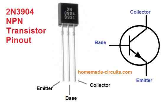
The pin outs of the transistor 2N3904 are given in the following diagram.
Applications
The 2N3904 NPN transistor is a widely used general-purpose transistor with a wide range of applications. The following are some typical applications for this transistor:
Amplification: In low-power audio, video, and RF applications, the 2N3904 is frequently utilized as an amplifier. It may provide voltage and current gain to a variety of circuits, such as oscillator circuits, small-signal amplifiers, and audio preamplifiers.
Switching: In digital and low-power applications, the 2N3904 may also be employed as a switch. It is frequently used as a switch to power relays, Lights, and other loads.
Oscillators: The transistor may also be utilized in oscillator circuits that require a consistent frequency output. Circuits for crystal oscillators, which are frequently employed in digital circuits.
Voltage regulator circuits: The 2N3904 may be used in voltage regulator circuits to regulate the voltage output of a power source.
It may also be employed in switching regulator circuits, which are used in power supply to effectively convert voltage levels.
Signal processing circuits, such as filters and equalisers, employ the 2N3904 to shape or adjust the frequency response of an audio or visual signal.
Overall, the 2N3904 is a versatile transistor that is often utilized in a wide range of low-power circuits, thanks to its low cost, high gain, and low noise properties.
How to Use
Here's a quick rundown on how to utilise a 2N3904 transistor in a basic circuit:
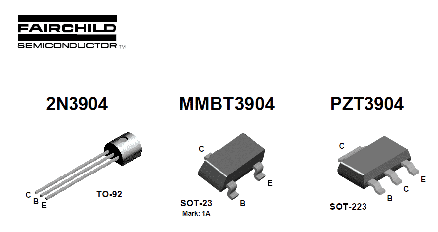
Determine the pins: The 2N3904 transistor has three pins: the emitter (E), base (B), and collector (C) (C). Typically, the emitter is linked to earth, while the collector is connected to the load (such as an LED or a speaker).
Determine the operating conditions: The transistor's operating circumstances (such as voltage and current levels) must be determined depending on the circuit's needs.
The maximum ratings and usual operating circumstances may be found in the transistor's datasheet.
Determine the base resistor (RB): The base resistor (RB) limits the current going into the transistor's base, which regulates the current passing through the collector.
Ohm's Law may be used to compute the value of RB, which is RB = (VCC - VBE) / IB. The supply voltage is VCC, the base-emitter voltage is VBE (usually approximately 0.7V), and the target base current is IB.
Connect the circuit: After calculating the base resistor, connect the transistor to the circuit. The base resistor connects the transistor's base to the input signal, while the collector connects to the load and the emitter connects to ground.
Summary
The datasheet of the transistor 2N3904 can be summarized as follows:
Absolute Maximum Ratings:
- Collector-Emitter Voltage: 40 V
- Collector-Base Voltage: 60 V
- Emitter-Base Voltage: 6 V
- Collector Current: 200 mA
- Total Power Dissipation: 625 mW
- Operating Junction Temperature: -55 to 150 °C
- Storage Temperature: -55 to 150 °C
Electrical Characteristics:
- Collector-Emitter Breakdown Voltage (IC = 10 mA, IB = 0): 40 V
- Collector-Emitter Saturation Voltage (IC = 10 mA, IB = 1 mA): 0.2 V
- Base-Emitter Saturation Voltage (IC = 10 mA, IB = 1 mA): 0.65 V
- DC Current Gain (IC = 1 mA, VCE = 10 V): 100 - 300
- Maximum Collector Current (DC) (VCE = 1 V, IB = 0): 200 mA
- Transition Frequency (IC = 10 mA, VCE = 20 V, f = 100 MHz): 250 MHz
- Input Capacitance (VCE = 10 V, IC = 0, f = 1 MHz): 8 pF
- Output Capacitance (VCE = 10 V, IC = 0, f = 1 MHz): 4 pF
- Reverse Transfer Capacitance (VCE = 10 V, IC = 0, f = 1 MHz): 1.2 pF
Questions & Answers
Dear Swagatam
I have read several of your transistor tutorials. Can your please explain all above in a complete detailed tutorial. For instance what are the above parameters, what they mean, where to use them and why? So far where ever I have read about transistors, they seems complicated or just incomplete in a sense that one site defines one thing and other sites defines some other parameters. A complete tutorial of a transistor so a newbe e can understand and utilize all important features of a transistor designing circuit himself, is yet to be seen.
Regards
Thanks Sam, for your keen interest.
I already have one related article posted in this blog, which you can eer to:
https://www.homemade-circuits.com/how-to-understand-and-use-transistors/
If you want more info included, please specify what exactly you are not able to understand, I’ll make sure to update them immediately for you in the most easy to understand explanation.