You might have searched regarding what is hysteresis a number of times through many different posts on different websites, but to no avail.
You might have also tried to find a comprehensive as well as an easy explanation regarding the same through various websites.
However, the explanations provided over these websites are pretty long and difficult to grasp.
Let’s try to learn through a simple example, what exactly hysteresis in an electronic circuit means.
How Hysteresis Works
The behavior of a relay towards a continuously applied variable voltage can be used to explain hysteresis concisely. I have explained it through the following experiment:
- Take a 12 volt relay, connect a variable power supply to it and gradually increase the voltage from zero to 12.
- You will find that the relay activates at about 11 volts. Logically, if now the voltage is reduced below this level, the relay should deactivate.
- However, that does not happen. Practically it will be seen that the relay deactivates only after the voltage is reduced well below 9 volts.
- This voltage lag between the activation and deactivation thresholds can be defined and understood as the hysteresis; in this case it is for the relay.
Similarly, all electronic circuits especially in single BJT circuit you will find this small disadvantage, which may pose difficulty in maintaining fixed thresholds levels.
In efficient electronic circuits the level of hysteresis is kept to the minimum. If you have more doubts regarding what is hysteresis, do feel free to respond with your comments.
Hysteresis in Opamp
On the contrary, opamps circuits tend to be very sharp and effectively avoid hysteresis while handling a specified operation.
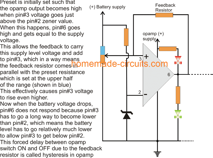
You might have come across many opamp based battery charger circuits, wherein the absence of a hysteresis actually becomes a disadvantage and we have to force hysteresis by adding a feedback resistor across the output and one of the input pins of the opamp to enable the hysteresis effect.
Therefore hysteresis in electronic circuits can be sometimes beneficial and sometimes a disadvantage depending on the application specifications of the circuit.

Questions & Answers
So, what does it mean when it is indicated in the datasheet that an input threshold is 1V and it has hysteresis at 100mV?
the input threshold is 1V, means the hysteresis is supposed to react at 1V threshold.
But it doesn’t ON and OFF instantly, at 1V…instead,
it will be ON only after it crosses maybe 1.05V (50mV above 1V).
then the hysteresis will turn OFF only after it drops below 0.95V (50mV below 1V).
So 50mV + 50mV corresponds to the 100mV figure…
Thank you
I have a circuit that uses a AC / DC adapter, a relay, and a ni-cad rechargable battery pack. As long as the circuit gets power from the wall, the relay keeps the battery pack off – thus the output is off.
Now when the power fails, the battery pack is switched in and the DC output device is switched on – simple.
I would like to have the other set of contacts to switch wall current to the re-chargeable battery pack to charge them when they are low. I currently have a voltage sensing circuit that can determine when the battery voltage is between 5-10 volts (I can set this). The problem I can “see” is that if the sensing circuit determines that the batteries need charging, voltage will be applied to them to charge. Now since the batteries have a full voltage across them, charging will stop. An oscillation loop. Someone told me that I needed to consider hysterisis to eliminate this loop. Hense – my post.
yes hysteresis can be used to prevent oscillation at full charge thresholds. However if a transistor is used instead of a relay then the oscillations cannot be a problem, since it will be silent and ensure the battery is always fully charged.
learning about hysterisis
How adding feedback resistor in OPAMO causes hysteresis? . please help to provide an application which benefits from hysteresis
You can find the explanation here:
hysteresis basically becomes important where the load is required to be switched ON and OFF at a specified threshold voltage level. Hysteresis makes sure that the load does not stutter or fluctuate at this threshold, instead its ON/OFF condition is separated by a small distance and this distance is called hysteresis.
An good example can be witnessed in an automatic day night lamp where the hysteresis ensures that the lamp does not flicker during twilight or threshold light intensities.
Hi,
Nice explanation!I however, have a question.Can I say that hysteresis is the lag/delay in activating or deactivating a circuit or a device due to stored electrical energy instead of calling it a voltage lag specifically?
Your reply would make my concept clearer.
Thanks in Advance!
Thanks Priyasha, in the case of relay it’s probably due to the mechanical characteristic which causes the lag, once the spring loaded pole gets attached to the relay electromagnet it is able to stay in that position with relatively lesser electromagnetic force, than what was required initially to pull it.
please explain hysteresis loop in memory storing device for example artificial synaptic devices ?