If you are an automotive technician, vehicle technician, or a motor mechanic, you may find this cheap yet powerful car battery charger circuit extremely handy, as it can be used for charging all types of car and motorcycle battery overnight with minimum effort.
This charger is specially suited for garages since it has a rugged and a maintenance free design, which allows the mechanic to use it without too many precautions. The only precaution that needs to be taken is the voltage selection between 6 V and 12 V, depending on the battery.
Another advantage of this solid state car battery charger is that the car mechanic can leave the battery unattended after connecting it with the charger, since the charger itself takes care of everything, right from auto full charge cut off to a current a controlled charging.

Main Features
- Inexpensive design, built using discrete ordinary parts.
- Adjustable charging voltage
- Adjustable charging current.
- Fully transistorized Solid State design.
- Suitable for all car and motorcycle batteries.
- Automatic cut off
- Charging level and status indicator
Full Charged Battery Improves Cold Cranking Amps
This circuit can also be used by all motorists so that they can be relaxed, especially on cold mornings. The unit will automatically charge the car's accumulator overnight so that during frozen mornings the car engine starts readily and at the first cranking.
While implementing an overnight battery charging unit, it becomes crucial to ensure that the battery does not get overcharged at any circumstances.
To make sure overcharging can never take place, the output voltage from the charger ought to be limited to the correct safe limit.
For 12 volt batteries the optimal safe charging voltage is approximately 14.1 V and for 6 V batteries it is around 7 V.
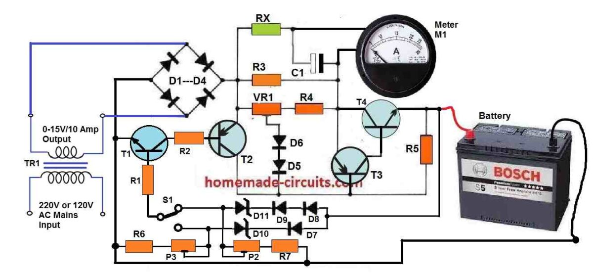
The full charge voltage threshold for 12 V car battery is adjusted using preset P2, and for 6 V motorcycle battery it is set by preset P3.
Circuit Diagram
Parts List
- All Resistors are 1/4 watt 5%, unless specified
- R1, R2 = 1.5K
- R3 = 0.33 Ohms 10 watt
- R4 = 68 Ohms
- R5 = 5.6K
- R6, R7 = 330 Ohms
- P2, P3 = 1K Presets
- VR1 = 100 Ohm 1 watt preset
- Capacitors
- C1 = 330uF/25V
- Semiconductors
- D1---D4 = 6A10 Diodes
- D5---D9 = 1N4007
- D10 =6.8 V 1 watt zener diode
- D11 = 12 V 1 watt zener diode
- T1 = BC547
- T2 = BC557
- T3 = BD140
- T4 = 2N3055
- Transformer = 0-15 V/220 V/ 15 amps
- Meter = 0-25 amps FSD moving coil Ammeter
How the Auto Cut-off at Full Charge Level Works
Overcharging situation is controlled through the following circuit operations.
While the battery charges its voltage level slowly climbs higher, until it reaches its 80 or 90% charge level. This is actually set by the presets P2 or P3 as explained previously.
Now, as the voltage level begins reaching the full charge level, the current begins dropping until it reaches almost the 0 amp mark. This is detected by the current sensor stage built around transistor T1/T2, or BC547/BC557, which instantly conduct and cuts off the bias to the base of T3 (BD140).
This in turn dries off the base bias for the power transistor 2N3055, shutting off the charging supply to the battery.
T3, T4 transistors actually behave like a high gain, high power PNP/NPN Darlington pair for effective transfer of current to the connected battery.
How Current Sensor Works
The current sensor stage using T1, T2, and preset VR1 can be used for setting any current between 2 and 6 amps for charging the relevant car battery. With 6 amp current a 60 Ah car battery can be charged within 12 hours to 80% level which is almost the full charge level of the battery.
How Charging Status is Monitored
The output charging current or the charging status can be continuously monitored through an ordinary ammeter. This could be any cheap ammeter rated appropriately.
The series resistors RX is used for suitably calibrating the meter response to full scale deflection initially, and 0V deflection at full charge.
The capacitor C1 ensures that the meter needle does not vibrating due to 100 Hz frequency from the bridge rectifier.
How the Circuit Prevents Desulfation
It must be noted that no filter capacitor is included in this car battery charger circuit, which helps to implement two factors: 1) cost and space saving, 2) Enhance battery life by minimizing the sulfation chances of the plates. The only single smoothing element in the charger is the car battery itself!
How to Set the Presets
As can be seen the presets P2, P3 are associated with a few rectifier diodes and zener diodes. When the 1K preset setting is at the maximum level, it sets the relevant outputs to 14 V and 7 V for 12 V and 6 V battery charging respectively.
The 1 K presets allow the user to fine-tune the full charge level to the preferred precise value. In case the maximum default value fails to reach the recommended levels of 14.1 V and 7 V, the user may add an additional rectifier diode with the existing D7, D8 or D9 diodes, and then tweak the 1K presets until the exact output full charge level is determined.
How to Set the Current Limit
The output current limit can be fixed by appropriately adjusting the P1 preset in the following manner:
Initially, keep the VR1 slider towards the 68 ohm resistor.
Connect a 10 amp ammeter across the emitter of 2N3055 and ground.
Now, slowly adjust VR1 until the desired maximum current is determined through the meter reading. This will fix the output charging current for the car battery at the required optimal rate.
Reference: Elektor
Fast Car battery Charger Circuit with Automatic Cut-off
Presented below is a dependable car battery charger that ensures faster battery charging compared to the standard four amps.
This enhanced speed is achieved by its ability to transition to a lower charging rate as the battery nears full capacity.
Moreover, it features safeguards against potential damage in cases of incorrect polarity during connection.
How the Circuit Works
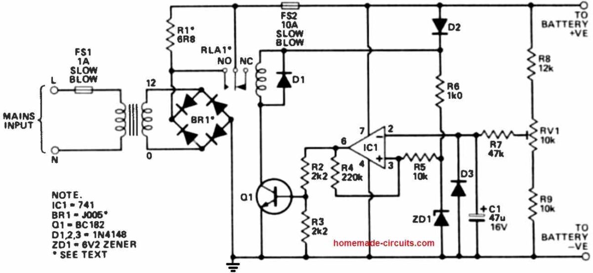
Assuming proper battery polarity, the sensing mechanism is activated through D2.
If the battery voltage is below the predetermined end-of-charge threshold, the relay is activated, directly linking the battery to the rectified transformer output, thereby facilitating rapid charging.
As the battery voltage rises to a sufficient level, the operational amplifier (op-amp) triggers a transition, turning off the relay.
This transition is not influenced by brief peaks in charging current, as the circuit smooths out such fluctuations using components R7 and C1.
D3 provides protection for C1 in the event of reverse polarity.
Following this, the battery voltage undergoes a slight reduction.
The relay, however, remains off due to approximately 1V of hysteresis applied to the op-amp (relative to battery voltage).
This hysteresis, combined with the ongoing lower-rate charging, ensures that the voltage doesn't drop to the critical level required to reactivate the relay.
Should a 24W car bulb replace R1, the bulb will emit a faint glow once the relay disengages. This serves as a visual indicator that the battery has reached its charging capacity.
A recommended practice is to activate the charger after connecting and deactivate it before disconnecting to minimize spark formation and the associated explosion risk.
Transformer Selection
The design doesn't prescribe a specific transformer as constructors can choose a suitable wattage.
For charging large automobile batteries like those in tractors or lorries, a higher current rating is essential.
A transformer with a minimum capacity of 50VA is suggested for this purpose, although it might not achieve an exceptionally fast charging rate.
If a charging current exceeding 10A is expected, a more robust bridge rectifier is necessary. Moreover, the relay contacts must match the maximum anticipated current.
The provided circuitry can be incorporated into existing standard battery chargers to prevent detrimental overcharging or to maintain battery charge during intermittent discharge cycles.
How to Setup
To fine-tune the circuit's cut-off point, a practical method involves connecting it to a well-charged car battery. By adjusting RV1, the relay should activate for two to three minutes.
This interval should be sufficient to raise the voltage to its peak without risking damage. Subsequently, RV1 can be adjusted to achieve relay deactivation.
This procedure should render the unit fully functional.
If the relay tends to reactivate even when the battery is suitably charged, the hysteresis can be slightly increased by reducing R4 to 180k or 150k.
If further reduction becomes necessary, it might indicate that the battery is below standard with potentially high-resistance cells.



Questions & Answers
Hi Swagatam
Thank you for this useful and detailed article.
Can a “Switch-Mode Power Supply” be used instead of the “transformer+bridge rectifier” in these circuits?
Thank you SA, glad you liked the article.
Yes, any power supply which can supply the required amount of voltage and current to the charger will work, so yes, SMPS can be also used for this purpose.
GOOD DAY SIR! PLEASE I WOULD LIKE YOU TO SUGGEST THE BEST AUTO CUT OFF BATTERY CHARGER CIRCUIT. JUST THE AUTO CUT OFF PART I NEED. THE ONE WITH RAPID RESPONSE AT THE CUT OFF VOLTAGE. AT LEAST THE ONE YOU ARE USING OR YOU HAVE USED AND CAN ATEST ITS RELIANCE. I HAVE TRIED SEVERAL ONES BUT THE CUT OFF POTENTIAL AT THE BASE OF THE NPN TRANSISTOR TO TRIGGER THE SWITCHING OF THE RELAY IS WIDE AND INCONSISTENT. FOR INSTANCE I MONITORED A CUT OFF POTENTIAL AT THE BASE OF BC547 TO BE 0.64V AND TRIGGER POTENTIAL TO BE 0.65V – 0.75V. IT TAKES A LOT OF TIME TO GET TO THOSE POTENTIAL AND BY THEN THE BATTERY VOLTAGE HAS EXCEEDED THE REQUIRED CUTOFF MARK. I OBSERVED THE TRANSISTOR STILL REMAINING TRIGGERED AT 0.62V AND UNTRIGGERED AT O.74V. I THINK THERE SHOULD BE ANOTHER TRANSISTOR NETWORK CAN DRY OFF THE BASE POTENTIAL AT A CERTAIN VOLTAGE SENSE.
Good Day Moses,
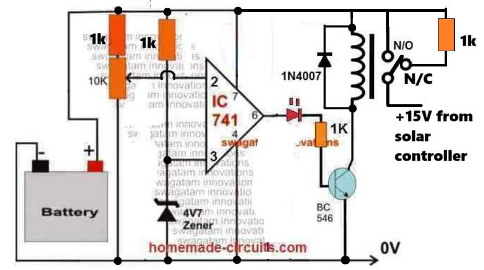
If you transistorized circuit then the triggering will never be accurate, so i would recommend you to go for an opmap based circuit such as the following one. This circuit will be highly accurate with the cut-offs, and will also provide trickle charging for your battery. Please connect a 10uF capacitor between the bse and ground of the transistor to avoid chattering or the relay at the thresholds:
ok thank you sir. what is the essence of 1k resistor between the nc and no of the relay. Does it suppose to connect to a LED as fully charged indicator.
The 1k enables trickle charging once the battery is fully charged and cut-off. You can change the 1k value for enabling any other desired trickle charging current…
Hi Swagatam, I’m designing a battery charger for the below specifications.
Output:
12VDC @ 10A max continuous current
settable voltage: 9V to 18V
settable current: 5A to 10A
settable output voltage trip: 10 to > 18V
Input:
240V AC Nominal(170 to 270V AC, 47 to 63Hz, single phase supply)
Filtering: Conducted emission
SMPS Frequency: 60KHz +/-10%
For these, requirements, can I utilize the part of your design. As I’m a beginner in power supply and battery charger design I needed some guidance on this.
Hi San,
Sure, you can use any of the above designs for customizing as per your specific needs.
Let me know if you face any issues with the application.
However I would recommend the second design from the above article which looks a better optimized circuit design.
Hi Mr Swagatam;
Is it possible to charge two batteries as serial at the same time but one’s current is 60A and others is 145A? Please consider the the condition is if the charging current is about 20A.
good day sir. please look at the relay contacts very well. The com and on contacts seem to be on the same power line even when the relay is not activated.
Moses, in the second circuit diagram, the relay connection is correct, when the N/O contact is not activated, the battery is trickle charged though the resistor R1
Hi Suat,
No, it is not recommended.
First of all 20A is too high for both the batteries if the batteries are lead acid type.
The optimal charging for the 60 Ah battery is upto 6 amps and for 145 AH battery it is 15 amps.
The other issue is the smaller battery will become fully charged much earlier than the bigger battery causing it to become overcharged which is bad.
Hi Mr. Swagatam;
My charger output is of 88,5V and 8,5A capacity. If I would connect the 6 different current capacity batteries as serial to test the charger in a short period, is it possible?
Let’s say; 3 batteries with the 60A capacity,
2 batteries with the 72A capacity
1 battery with the 100A capacity
Hi Suat,
Yes, for the testing purpose you can do it.
Thanks Swagatam. I can limit the period less than 30 seconds or even it may be 10 seconds so is it possible to connect 5 pcs or less of the batteries? Or 88,5V is too high?
Hi Suat, actually the full charging voltage across any battery must not exceed its specified rating even for a short duration of time, so you must take care and be careful of this situation.
Thanks Vahik
??????
Sorry for the confusion. P1 is not there, P1 was actually referred to VR1.
I have now removed the P1 from text, which was wrongly mentioned.
Hello, just finished this charger at the 1st diagram. Have set up the current to 3A by connecting the ammeter to + and – at the output. The same way set up the desired voltage to 14.2V. After connecting the car battery, nothing is happening. The voltage, keeping the battery connected to the output, is 12.56V and not increasing over time.
Hello, It is difficult for me to troubleshoot the first circuit because there are many parts in it and I cannot verify your circuit connections.
Still you can check the following. Remove the battery and check the output voltage with a meter, it should change when you toggle the switch S1.
If this happens then your circuit’s voltage control is good. Now keep VR1 midway and connect a 10 amp or 5 amp ammeter across the output terminals of the circuit and check the current. Adjust the VR1 and check whether this causes the ammeter to show different current ranges or not.
Maybe it will ring a bell what might be wrong.
If I connect the battery and hardwire C with E on T4 (2N3055) it starts to charge. The current is slowly increasing, have left it like this for a few minutes only.
After disconnecting the wire between C and E, the measured voltage is as follows:
a) battery not connected:
Ucb 3.76V / Ube 0V / Uce 4.24V
b) battery connected (have tried 2 different types for 12V)
Ucb 6.26V / Ube 0.68V / Uce 7V
Can please tell your battery Ah specifications, and how much current have you applied for the circuit output?
43Ah, applied 2A and 3A, no difference.
Is the meter showing current when battery is connected? If yes then your battery is getting charged. If the battery consumes 3 amps and the input current is also 3 Amps then the charging voltage should drop initially, and then slowly rise within 10 hours time, as the battery gets full charged.
That is the issue, no current on the output at all when battery is connected.
What happens when you connect an ammeter in place of the battery, or maybe a lamp? If the meter shows current, or if the bulb illuminates then your battery maybe faulty or malfunctioning.
That
s the funny thing. One battery is a few years old, and the 2nd one just removed from the car where it worked for years. I just decided to bough a new one and build a charger to take care about it.s what I have tried when assembled all parts together to check the functionality.The light bulb reacts to Ampere or Voltage changes as expected - that
Please try the following circuit:
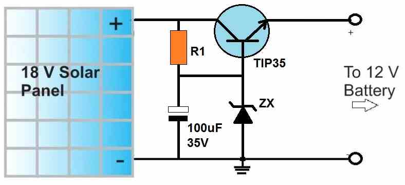
Replace the zener with a 15V zener diode.
For the resistor use a 220 Ohm 1 watt resistor.
You can use a 2N3055 for the transistor, if required.
Now connect your 12V battery and check the response.
If still the battery does not charge then certainly your battery is not good.
Thanks, yes it works exactly as you have described.
Hi, I am interested to build this garage battery charger. I would like to change the supply transformer to 230vac/ 24vac. I assume the two zener diodes will need to be changed and also to include a small panel digital 0 – 30 vdc / 0 – 10 amp dc meter. Anything else that requires changes? The required pot to adjust final cut off supply to battery when fully charged to close to 28 volts dc.
Looking forward to your reply.
Regards Yule
Hi, Yes that’s right. In addition to that you may also have to modify the value of R3.
For R6, R7 you can use 1k 1/4 watt.
However 2n3055 might not be able to handle 10 amp current. You can use a TIP35 instead.
This circuit actually is an overkill, the same results or even better results can be obtained using two or three LM338 ICs in parallel with a current limiter stage.
Hello sir I have already done my but I didn’t used your specs instead the npn trsis I used d882 and the pnp trsis I used h772 please can it be working correctly for me?
Hello Lord,
The transistor numbers must be exactly as shown in the diagram, any other value may cause malfunctioning or other issues.
I love your site and all the great schematics are great. I just have one question is it ok to build the battery charger just as you show it or are there any changes such as mentioned in the comments.
You can build the above battery charger without any changes, however there are much simpler options than the above design using LM338 IC
Can I use a transformer with 24vac of secondary to this charger ?
Yes you can use it.
Hello
is it possible to find the pcb for this circuit? I want to put this circuit in a commercial battery charger
thx
Hi, sorry, unfortunately a PCB design is not available for this project!
Can someone send a pattern of the mounting plate?
Hello.
If memory serves, the scheme from the magazine Elector (1976/7) ))))
Hello, thanks, can you please show me the link of the article? I will do the needful.
Hello.
I attach links, but they are not here .. for some reason?
Can I send it by mail or whatever is convenient for you?
OK thank you, I got the link sent. I will give the attribution through this at the bottom of the article. Will it be OK?
https://www.elektormagazine.com/magazine/elektor-197607/57722
Of course, whichever is more convenient for you.)))
OK thanks very much!
How can I put more transistors in parallel to reduce the dissipation of a single transistor?
You can use TIP35 transistor to increase the output power….
Hi dear, tnk you for your circuit !
I think there is a correction to do in what you wrote about the set to “output voltage regulation”
I.e., where you wrote :
“The full charge voltage threshold for 12 V car battery is adjusted using preset P2, and for 6 V motorcycle battery it is set by preset P1”
…. i think that the correct function of the 3 trimmers is :
VR1: set CURRENT output
P2 : set 12V voltage output
P3: set 6V voltage output
Hi, your assumptions are perfectly correct!
Hello mr. Swag thanks for posting this circuit!
I’m going to build this battery charger for my father to use, he enjoys working with his car.
One question, in the current sensing part of the text it is mentioned that by adjusting VR1 you can set up the charging rate from 2 to 6 amps.
Sometimes my dad prefers to trickle charge his batteries with current as low as 100mA, if i increase P1 resistance value will I be able to reduce current that low?
Hello Fifo, 100mA is too small to be sensed and fixed by the T3 transistor. For trickle charging you can simply connect a bypass resistor across the emitter/collector of the 2N3055 transistor. When this transistor switches off, the trickle charge current starts flowing to the battery via the bypass resistor.
What is value of RX which before the Ammeter?
You will have to find it through some practical experimentation
What could be the value of Rs resistance?
As per the meter specs, higher value if the meter is an uA, lower if it’s a mA
Thank you for the reply.
Greetings, first of all thank you very much for sharing your knowledge with us, your car battery charger project is very interesting, I am currently working on the manufacture of one, but I am only interested in the current sensor part, since I plan to use a controller module charging already prefabricated since it considerably reduces the cost .. could you help me to adapt only the part of the current sensor, so that I can have the option of a fast and a slower charge .. I thank you in advance for a timely response ..
You are most welcome. I think you can add the current control system externally by using the 3rd concept from the bottom, in this article:
https://www.homemade-circuits.com/universal-high-watt-led-current-limiter/
The input supply can be from your existing charger unit, and the load can be replaced with your battery.
Hello, I’m Ari from Brazil, interesting about your projects, I would like you to publish a circuit to balance the charge of 2 batteries of 12 volts in series and solar charger of 24 volts .grateful ARI.lead acid battery balancer circuit.
Hello, I think I already have a 2 battery balancer circuit in this site:
Dual Battery Charger Circuit with Isolator
In this article you will get to know in detail about the regulated car battery charger circuit for the garage. Things to be considering include many options listed in this link. It is very useful article and would suggest others too. I am sure many people will come to read this in future.
Hi, do you have any DC-DC power supplies schematic ?
You can check out the following links and the pages
https://www.homemade-circuits.com/category/ac-dc-adapter/
Hello sir can you tell me that what is the difference of charging between lead acid and lithium ion if i am using auto cutt-off. Plz clear my ambiguity.
Thanks
Hello Adil, the main difference is that, Li-ion battery can be charged with 100% of their Ah value, while the recommended charging rate of lead acid battery is only at 10% of their Ah value. Auto cut off is compulsory for both types if the maximum charging voltage is set at the standard full charge level which are 14.4V for 12V lead acid battery, and 4.2V for 3.7V li-ion
thank YOU SIR FOR REPLYING SIR but what i have read that charging batteries with c/2 is best for lithium ion so if i am making a charger for lithium ion then c/5 rate should be enough for my battery but if i charge my battery at c/2 rate then i think we have to make an intelligent circuit to compensate heat issues.
Sir i am a student and wanted to do some research on batteries and wanted to build a charger for lithium ion of rating 12v 14ah, i have seen many circuit of lithium on your site but they all are on 4.1 v rating but as you can see my rating is so high, So what circuit do you suggest and what changes should be made in your given circuit for my battery rating.
And curiously i was also thinking of making a charger that can charge my both Lead and Li batteries what do you think?
And sir how can i do float charge for my Lead Acid battery?
Thanks
Adil, The main advantage of Li-ion batteries is that, they can be charged very fast through 1C rate current, equal to their Ah rating, which is not possible with a lead acid battery. Although at this rate the battery may warm up significantly and may require an additional temp compensation circuitry attached.
At c/2 the charging will be slow, and the above advantage cannot be exploited.
Nevertheless, charging at slower rate ensures the battery never heats up, so no extra circuitry required, and the battery life is also enhanced due to lower level of stress on the battery.
For your battery you can use a maximum voltage of 12.5V, and this will not require any auto cut off, since it is lower than the full-charge level of 12.6V
You can use the above recommended design for both li-ion and lead acid battery at c/2 rate. For float charge keep a 100 ohm 1 watt resistor connected directly from battery positive to the supply positive
I am a beginner and would like to build the above battery charger from your sketch.
What I do not understand, is the green resistor indicated with RS.
I need a list of components and on this one I have lost you. Could you please advise what this resistor’s value is or how should I describe it to the electronics store?
The RS is a current limiting resistor which must be adjusted to a value that allows the meter to produce a full scale deflection at the maximum current from the battery charger. This will allow the meter to be calibrated right from from 0 to the maximum available capacity of the unit.
….You may have to experiment the value by trying different resistors, until the right one is found which allows the meter to produce a full scale deflection at the maximum load current from the unit
Is this one complete , i want to make one for my personal use. Can any body help me.
yes, it is 100% complete and working.
Thanks sir for replying and answering my questions, sir as you told me that this circuit can charge both lead acid and lithium ion batteries but i think we also need to float charge lead acid battery unlike lithium ion and you told me to use 100 ohm resistor, So sir if i am using this same circuit for lithium ion then my current should be c/2 but this same circuit for lead acid would be required of 1/10 C of rating so how i am gonna do that keeping in view that i want to charge two batteries having different charge methods with the same charger ?
And sir i also read that in lithium ion current should be cutt off at almost 3% of rating C whereas in lead acid i need to keep on float charge, But you told me that cutt off is needed for both batteries, Plz can you explain how?
And at last sir can you give me a circuit for temperature sensing while charging in battery that i can use with this circuit for battery.
Waiting for your reply
Thanks
Adil, you can change the charging rate by adjusting the P1 pot accordingly.
There are no critical rules for charging batteries except having a correctly controlled voltage and current and an auto cut off at full charge.
Float charging is required if you are not using the battery immediately after full charging.
At C/2 charging you may not need a temperature control.
For over 1C you can use the following circuit, and configure the output appropriately for temperature compensation:
https://www.homemade-circuits.com/lm35-circuit/
*.Good morning ENGR. Can this circuit above charge inverter battery 200amps normal?
*.Please can you help me with ferrite core transformer battery charger. For 200A battery
Hello Sunshine yes it is possible if the 2N3055 is replaced with 3nos of TIP142 in parallel.
sorry I do not have a ferrite based design at this moment.
For 12V car battery maybe is better zener diode 13V+2diodes 1n4001 instead zener diode 12V+2diodes and for battery 6V zener diode 6V2+1 diode.
I am a 72 year old mechanical engineer who is thying to learn about electronics.
I built the circuit but I get 10.6 volts on the 12 volt position and 9.4 volts on the 6 volt position.
What should I change to get these numbers closer to 14 volts and 7 volts?
Thank you for trying this circuit, Your input supply voltage must be above 15 V, only then the output will indicate the respective voltages correctly.
If you still have problems, you may try adding a couple of more 1N4148 diodes in series with the existing diodes.
Yes that may be true, I hope the readers will take a note of this.
Hello, Thank you for your work through this site.
Can you please explain how would the transistor BC547 activate? Does it mean that the battery voltage should be about 0.7 + 0.6 + 0.6 + 13 = 14.9 V?
For 12 V battery, the voltage should be 0.6 + 0.6 + 13V = 14.2V. When this voltage is crossed, it will reach the base of the BC547 and trigger it ON, which will switch Off the 2N3055
Is it possible to add reverse polarity protection in this ckt?
It is possible by using a relay stage at the output.
is this battery charger for sale, or is it intended that the whole must be made yourself, in this case, a lot of information is missing
It is for construction purpose, yes there are a few things missing, for example, how to set the presets, and how to calibrate the meter. I’ll try update them soon….
Sir is this circuit as it, IS suitable for Lithium ion and for Lead acid i can use 100hm resistor for Float charge?
and how can i set presets?
And if this circuit can charge both Lead and Lithium ion batteries then why we have numerous circuits separate for individual lead and lithium ion(or what is the differnce between this and other Lithium ion circuits?)>?
Adil, I have already explained you elaborately regarding the differences between the two batteries. Special chargers are created for the layman users who have no idea how to change the charging parameters, and to ensure fastest charging for the respective batteries.