In this post we learn how to build a battery deep discharge protection circuit which can be used for protecting any type of battery from over discharge through a connected load.
Normally, we are mostly worried about battery getting over charged, and forget about a situation where the battery can get over discharged by the load. Although, overcharging a battery may be detrimental to a battery health and appropriate measures must be incorporated, an over discharge or a deep discharge can be also equally dangerous for a battery's health.
In the following paragraphs we will discuss a very simple design for shutting off the battery to the load, as soon as the battery voltage has reached the critical deep discharge state.
The circuit is fully solid-state and uses only transistors for the switching, thus eliminating the need of bulky relays.
Circuit Specifications
The idea was actually requested by one of the dedicated readers of this blog, Mr. Saurav, as explained below:
Looking for some ideas/help/suggestions. I have installed a 2.2 kw off grid solar system, using loom solar panels, excide battery and excide solar inverter. The inverter has this pre-setup priority, first solar, then grid, last battery. I have disconnected the mains supply to the inverter, so for me it is solar then battery. To this overall setup, I have added an ACCL with grid as secondary.
So in the evening, whenever there is no solar and the battery is out of charge, it falls back to grid power.
This setup has one problem. ACCL switches to mains power at night, when the battery is completely drained out or deeply discharged and that's what I don't want.
I want to turn off the battery power, when the battery has 20% remaining power or the battery is at a certain voltage. That way battery life can be better.
Is this something doable? Do we have something readily available for this? Or do we need to build something for this?
The Design
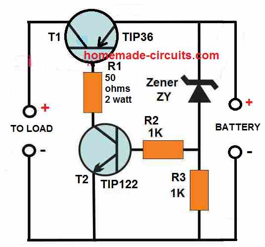
The circuit design for the proposed battery deep discharge protection circuit can be witnessed in the following diagram:


As can be seen, the circuit has a very components, and its working can be understood through the following points:
There are a couple of power transistors coupled with each other where, the base of the TIP36 transistor forms the collector load of the TIP122 transistors.
The base of TIP122 is biased through a resistor/zener diode network, where the zener diode ZY determines the cut off voltage for the TIP122.
The zener diode voltage is selected such that it matches the critical low voltage value of the battery, or any value at which the draining of the battery by the load is required to be stopped.
As long as the battery voltage stays above the zener voltage, or the voltage at which the cut-off needs to happen, the zener diode keeps conducting which in turn keeps the TIP122 in the conducting mode.
With TIP122 conducting the TIP36 gets the required base current, and it also conducts and allows the battery current to pass to the load.
However, the moment the battery voltages reaches or drops below the zener voltage which is also the deep discharge voltage level, causes the zener diode to stop conducting.
When the zener diode stops conducting, the TIP122 base voltage is cut off and it switches OFF.
With TIP122 now switched OFF, the TIP36 is unable to get its base bias current, and it also switches OFF turning off the battery current to the load.
The procedure effectively prevents the battery from further draining and depleting below its deep discharge level.
The indicated load can be any specified load, such as an inverter, a motor, an LED lamp etc.
How to Select the Zener Diode
The zener diode decides at what voltage the battery needs to cut off from the load. Therefore, the zener voltage must be approximately equal to the battery voltage at which the cut off needs to happen.
For example, if for a 12 V battery, the deep discharge cut off value is 10 V, then the zener diode ZY value can be also selected to be 10 V / 1/2 watt.
Using a MOSFET
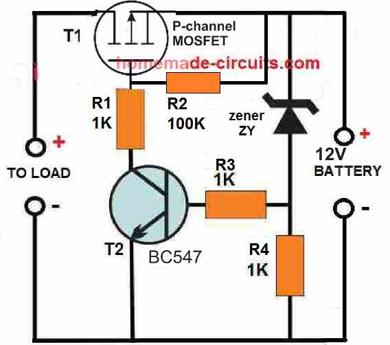
The indicated TIP36 can supply a maximum current of 10 amps to the load. For higher current, the TIP36 could be replaced with a P-Channel MOSFET such as the MTP50P03HDL, which is rated to handle at least 30 amp current.

When a MOSFET is used in place of the BJT TIP36, the 50 ohms resistor can be replaced with a 1K resistor or a 10K resistor, and the TIP122 can be replaced with a BC547.
Adding a Battery Charger with a Single Transistor
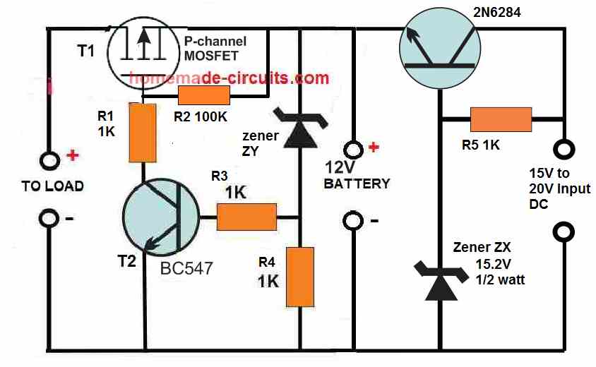
The above discussed concepts are used to handle the over discharge situation of a connected battery. However, if you want the above circuit to also have its own battery charger, then the following circuit can be used for the process effectively.

Here we can see a transistor stage on the right side of the design, which is configured as an emitter follower. The transistor is a 2N6284, which is rated to provide at least 10 amp current to the battery, which means it is able to charge even a 100 Ah battery efficiently.
Since the transistor is a Darlington transistor and configured as an emitter follower, the voltage at its emitter will always lag behind its base voltage by 1 V or 1.2 V.
The zener diode must be cautiously selected so that it compensates the emitter drop of 1.2 V by providing a potential at the base which may be 1.2 V higher than the required emitter voltage.
Since the circuit is designed to charge a 12 V battery, the full charge voltage at the emitter of this transistor must be around 14.1 V. This implies that the base voltage of the transistor must be 1.2 V higher than the emitter, which amounts to a value of around 15.2 V to 15.3 V.
This is exactly why the zener must be rated at the above specified voltage for generating a constant 14. 1 V at the emitter side and across the connected 12 V battery.
While charging the battery when the battery terminal voltage reaches the 14.1 V value, it reverse biases the emitter of the 2N6284, which shuts down the conduction of the transistor, thereby stopping any further charging of the battery, and the battery is safeguarded from over charging.
The above shown circuit thus implements a 2 in 1 procedure of preventing battery over deep discharge and also over charging through the use a just a few transistors, and still is able to control a battery that may be as big as a 12 V 100 Ah battery.
Have Questions? Please Comment below to Solve your Queries! Comments must be Related to the above Topic!!