In this article I have explained a simple low dropout LDO, or zero drop solar charger circuit without microcontroller which can be modified in many different ways as per user preference. The circuit does not depend on microcontroller and can be built even by a layman.
What is a Zero Drop Charger
A zero drop solar charger is a device which ensures that the voltage from the solar panel reaches the battery without undergoing any drop in voltage, either due to resistance or semiconductor interference.
The circuit here uses a MOSFET as a switch for ensuring minimum drop in voltage from the attached solar panel.
Moreover the circuit has a distinct advantage over other forms of zero drop charger designs, it does not unnecessarily shunt the panel making sure the panel is allowed to operate at its highest efficiency zone.
So I have explained how these features could be achieved through this novel circuit idea designed by me.
Simplest LDO Circuit
Here's a simplest LDO solar charger example which can be built in minutes, by any interested hobbyist.
These circuits can be effectively used in place of expensive Schottky diodes, for getting an equivalent zero drop transfer of solar energy to the load.
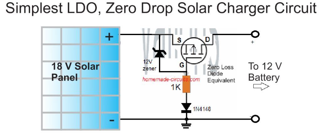
A P channel MOSFET is used as a zero drop LDO switch. The zener diode protects the MOSFET from high solar panel voltages above 20 V. The 1N4148 protects the MOSFET from a reverse solar panel connection.
Thus, this MOSFET LDO becomes fully protected from reverse polarity conditions and also allows the battery to charge without dropping any voltage in the middle.
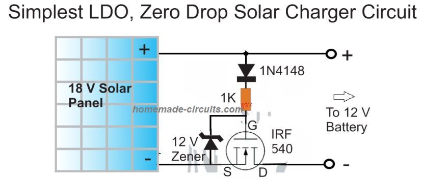
For an N-channel version you can try the following variant.
Using Op Amps
If you are interested to build a zero drop charger with automatic cut off feature, you can apply this using an op amp is wired as a comparator as shown below.
In this design the non-inverting pin of the IC is positioned as the voltage sensor via a voltage divider stage made by R3 and R4.
Referring to the proposed zero drop voltage regulator charger circuit diagram we see a rather straightforward configuration consisting of an opamp and a mosfet as the main active ingredients.
The inverting pin is as usual rigged as the reference input using R2 and the zener diode.
Assuming the battery to be charged is a 12V battery, the junction between R3 and R4 is calculated such that it produces 14.4V at a certain optimal input voltage level which may be the open circuit voltage of the connected panel.
On applying the solar voltage at the shown input terminals, the mosfet initiates with the help of R1 and allows the entire voltage across its drain lead which finally reaches the R3/R4 junction.
The voltage level is instantly sensed here and if in case it's higher than the set 14.4V, switches ON the opamp output to a high potential.
This action instantly switches OFF the mosfet making sure no further voltage is allowed to reach its drain.
However in the process the voltage now tends to fall below the 14.4V mark across the R3/R4 junction which yet again prompts the opamp output to go low and in turn switch ON the mosfet.
The above switching goes on repeating rapidly which results in a constant 14.4V at the output fed to the battery terminals.
The use of the mosfet ensures an almost zero drop output from the solar panel.
D1/C1 are introduced for maintaining and sustaining a constant supply to the IC supply pins.
Unlike shunt type regulators, here the excess voltage from the solar panel is controlled by switching OFF the panel, which ensures zero loading of the solar panel and allows it to operate at its most efficient conditions, quite like an MPPT situation.
The LDO solar charger circuit without microcontroller can be easily upgraded by adding an auto cut off, and an over current limit features.
Circuit Diagram
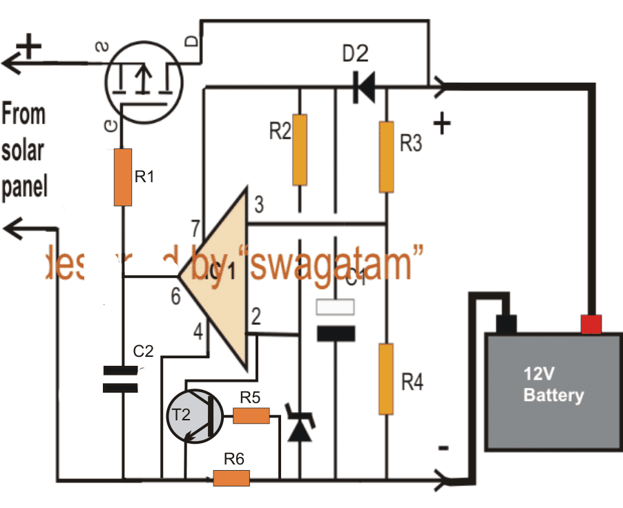
NOTE: PLEASE CONNECT THE PIN#7 OF THE IC DIRECTLY WITH THE (+)TERMINAL OF THE SOLAR PANEL OTHERWISE THE CIRCUIT WILL NOT FUNCTION. USE LM321 IF THE SOLAR PANEL VOLTAGE IS HIGHER THAN 18 V.
Parts List
- R1,R2 = 10K
- R3,R4 = use an online potential divider calculator for fixing the required junction voltage
- D2 = 1N4148
- C1 = 10uF/50V
- C2 = 0.22uF
- Z1 = should be much lower than the selected battery over charge level
- IC1 = 741
- Mosfet = as per the battery AH and the solar voltage.
Using N-Channel MOSFET
The proposed low dropout can be also effectively implemented using an N-channel MOSFET. as indicated below:
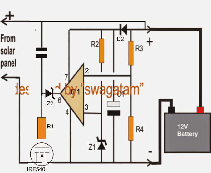
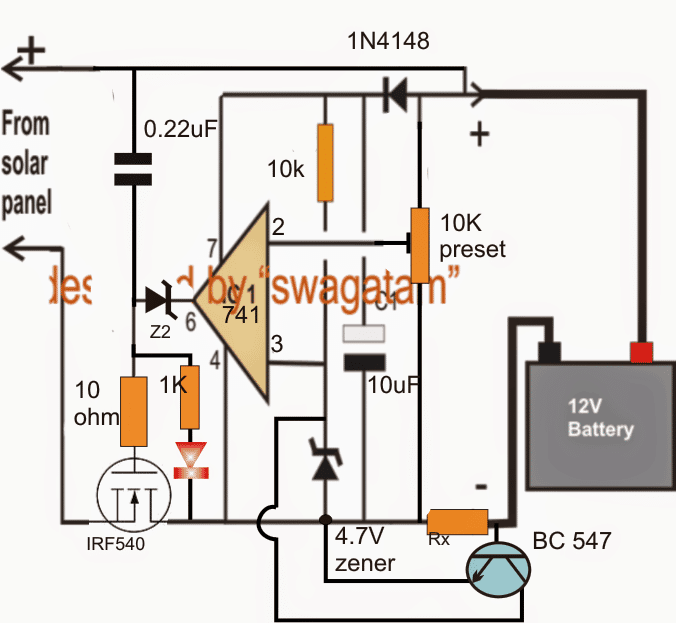
NOTE: PLEASE CONNECT THE PIN#4 OF THE IC DIRECTLY WITH THE (-)TERMINAL OF THE SOLAR PANEL, OTHERWISE THE CIRCUIT WILL CEASE TO WORK. USE LM321 INSTEAD OF 741 IF THE PANEL OUTPUT IS HIGHER THAN 18 V.
Adding a Current Control Feature
The second diagram above shows how the above the design may be upgraded with a current control feature by simply adding a BC547 transistor stage across the inverting input of the opamp.
R5 can be any low value resistor such as a 100 ohm.
R6 determines the maximum allowable charging current to the battery which may be set by using the formula:
R(Ohms) = 0.6/I, where I is the optimal charging rate (amps) of the connected battery.
Finalized Solar zero drop battery charger circuit:
As per the suggestion of "jrp4d"the above explained designs needed some serious modifications for operating correctly. I have presented the finalized, corrected working designs for the same through the below shown diagrams:
According to "jrp4d":
Hi - I've been messing about with Mosfets (voltage control circuits) and I don't think either circuit will work except where the line in voltage is only a few volts large than the target battery voltage. For anything where the line in is much more than the battery the mosfet will just conduct because the control circuit can't control it.
In both circuits its the same problem, with P-channel the op-amp cant drive the gate high enough to turn it off (as observed by one post) - it just passes the line voltage straight thru to the battery. In the N channel version the op-amp can't drive the gate low enough because its operating at a higher voltage than the -ve line in side.
Both circuits need a driving device operating at the full line in voltage, controlled by the op-amp
The suggestion above looks valid and correct. The simplest way to rectify the above problem is to connect Pin#7 of the opamp IC with the (+) of the solar panel directly. This would instantly solve the issue!
Alternatively the above designs could be modified in the manner shown below for the same:
Using NPN BJT or N-channel mosfet:
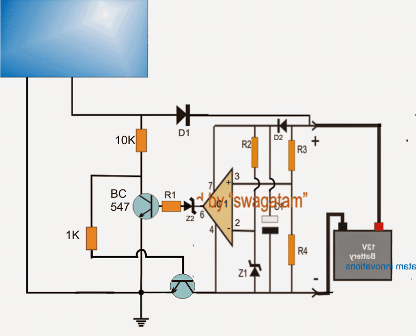
In the above figure the NPN power transistor could be a TIP142, or a IRF540 mosfet .....and please Remove D1 as it's simply not required.
Parts List
- R1, R2 = 10 K
- R3, R4 = use an online potential divider calculator for fixing the required junction voltage
- D2 = 1N4148
- C1 = 10 uF / 50 V
- C2 = 0.22 uF
- Z1 = should be much lower than the selected battery over charge level
- IC1 = IC 741
- Lower Transistor = TIP142 or as per the battery Ah and the solar voltage.
Using PNP transistor or P-mosfet
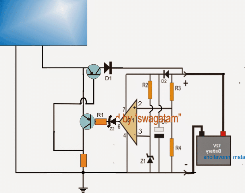
In the above figure, the power transistor could be a TIP147 or a IRF9540 mosfet, the transistor associated with R1 could be a BC557 transistor......and please Remove D1 as it's simply not required.
How to Set up the LDO solar charger circuit
It's very easy.
- Do not connect any supply at the mosfet side.
- Replace the battery with a variable power supply input and adjust it to the charging level of the battery which is supposed to be charged.
- Now carefully adjust the pin2 preset until the LED just shuts off....flick the preset to and fro and check the LED response it should also blink ON/OFF correspondingly, finally adjust the preset to a point where the LeD just shuts off completely....seal the preset.
- Your zero drop solar charger is ready, and set.
You can confirm the above by applying a much higher input voltage at the mosfet side, you'll find the battery side output producing the perfectly regulated voltage level that was previously set by you.


Questions & Answers
Thank you sir for always there as a source of knowledge for everyone of us. May God continue to enrich your wisdom sir.
I wish to ask wether Zener diode(Z²) at pin 6 of the ic must be there or not. If must be there, what is the rated voltage of the zener diode.
my second question, at my location, i could not find LM741 ic but i see UA741. what is the alternative ic to LM741 can you recommend please.
Thank you sir.
Thank you Emmanuel, for your kind words, I am always happy to help!
The zener diode is used to block leakage voltage from the opamp output while it is at logic 0V. Because even while it is at logic 0V, it leaks around 1V to 2V, and the zener diode blocks this voltage. The zener value can be a 3V. You can also replace the zener diode with two 1N4148 diodes in series (anode towards pin6).
LM741 is not compulsory at all. you can easily replace it with any other standard opamp or even with a LM393 comparator…just beware of the pinouts which may be different for different ICs.
Is this the same as an ideal diode? Do you have an ideal diode topic?
Yes, better than an ideal diode…
What is the difference?
Diode is not 100% zero drop, but the transistor versions are almost 100% zero drop…
please how can I reconfigure to do120v input for 10 batteries, with 170 solar input. hope for a favourable response
I made the second to last circuit npn type for a 24v system, it controlled well but when the sun shines for long and it is full, the mosfet gets very hot even with heatsink and fan.
is there anything to do to reduce pressure on the mosfets, I used 10pcs irfp 260 for 150w panels 2 Pcs @ 22.8v
What is your battery Ah rating? Please remove the gate 1k resistor, and check again…
Thanks sir. 100ah batteries
Ok, please remove the 1k from the MOSFET gate…
You can configure the following regulator circuit with each battery separately.
The transistor, R1, and the zener values will depend on the battery specifications.
https://www.homemade-circuits.com/wp-content/uploads/2022/09/solar-regulator-emitter-follower.jpg
Thanks, I don’t understand how this circuit will be connected with each battery and the overall 170v solar input.
please kindly guide, sir
Please tell me how are the 10 batteries connected with the solar panel voltage? And what is the voltage rating of each battery? I will try to solve it.
Thanks sir, the panels are connected in series to get 170v, the batteries each is 12v 40ah.
OK, that means the 10 batteries are also connected in series?
Yes sir
Dan, In that case you can use the previous circuit which I suggested, and connect it between the solar panel and the series battery bank.
Replace the transistor with MJ10022,
Replace the zener diode with a 141V zener diode,
Replace the resistor with a 10k 5 watt resistor.
The mosfet in this circuit will only work when the battery has the lowest internal resistance. Otherwise-overheating and failure.
Mosfet does not have time to give heat to the radiator.
I try 2nd circuit (Simplest LDO N-MOS) but when solar panel voltage drop below battery voltage, then current flow back to solar panel. I want to replace schottky diode with your circuit. How could I do?
Please replace the MOSFET with a BJT and try again. Let me how it goes.
Good day Swag, I designed the second to last circuit for solar controller 3years ago, worked perfectly without fans, but recently I designed same circuit but the mosfets blow without fan. Now I must use fan, please what could be wrong.
Hi Seun, are you referring to the following circuit?
https://www.homemade-circuits.com/wp-content/uploads/2013/08/zero-1.png
I guess you used the mosfet in place of the upper power transistor.
As you can see that the upper transistor has only the battery as the load. If your mosfet is correctly rated to handle the battery current then it should not heat up much.
You can try using a BJT instead of a mosfet and check the results because BJTs are more reliable and predictable than mosfets.
Try using a TIP36 and makes sure the base resistor (ground resistor) is adjusted correctly for maximum current delivery.
Please how can I use one circuit of the n-channel MOSFETs below to control 4 DIFFERENT SOLAR system setups, can it supply adequate voltage to the gate?
Can I modify the circuit for 6V battery, how, Sir?
Thanks
Tinu, I did not understand your question…which circuit are you referring to?
Using the second to the last circuit here, can one circuit used to drive 4 MOSFETs sets, single for 4 different solar systems, e.g say 1kw solar system for 4 different inverter power systems.
Also, how can I modify it for 6v battery?
For 4 different solar panels, 4 different op amp circuits would be required, a single circuit cannot be used for controlling 4 solar panel systems.
6V can be used but only R3/R4 will need to be changed accordingly.
Hi Swagatam. It’s Chris ????
I’ve got two solar panels here and both are 150watt panels.
But the problem here is that their voltages don’t match. One has an open circuit voltage of 23.5v(which even rises to 24v most times) the other panel has open circuit voltage of about 21.2v.
Is there a way to connect them both to my solar charge controller so that I can make use of them both to charge my 100Ah solar battery?
Just a suggestion. I was thinking of building your circuit above but with lm324(where I’d make use of two it’s opAmps) for each panel to lower down their their voltages to a common voltage (let’s say 19v or 20v) then connect them in parallel and feed it to the solar charge controller.
Please if you’ve got any other better ideas please help me. Thanks.
Hi Chris,
Surely you can do that! You can build two of the following circuits and connect their outputs in parallel to feed your controller circuit. Make sure to mount the transistor over a very large heatsink.
Thanks for the response.
1) Please what are the values for R1 and Zx that would give Me the required amount of volts I need for this purpose?
Can I replace TiP35 with TIP41c as this former is not available here, but TIP41C is.
Okay.
1. How about in each Solar panel’s circuit, I connect two TIP41c in parallel(just like MOSFETs in parallel). would it help increase the amount of current each circuit would deliver?
Or can I use MOSFETs in the circuits in place of the the transistors?
You can connect them in parallel, just make sure they are mounted on a common single heatsink, very close to each other.
MOSFET source follower will drop around 5V so that may not be very efficient.
Alright. Mr swag, Thank you so much.
I’d do just that. If I encounter anything else. I’ll be sure to text you.
No problem Chris, all the best to you. Let me know if anything goes wrong.
R1 will need to be experimented to find which value provides the maximum solar panel output current.
TIP41 cannot be used since the 100 Ah battery would require 10 amp current minimum,and each panel would need to deliver 5 amps each….TIP41C cannot handle 5 amps.
Hi Swagatam. I’m kinda new to making circuits.
1) I’m confused on how to setup the circuit. You made mention of using a LED to test the circuit. Where am I going to connect the LED?
2) In your above circuit (after the 5th circuit posted in this page), you made mention that pin 4# should be connected directly to the (-ve) of the solar panel(i.e for the NPN mosfet version). My question Is, should we still connect pin7# directly to the (+ve) of the solar panel as well? Or ignore connecting pin7# directly to +ve of the solar panel but ensure we connect pin4# to the -ve of the panel?
Note: this questions are for the NPN mosfet version.
Thanks.
Hi Chris, The set up procedure is explained for the last two circuits. I am sorry, I forgot to show the positions of the LEDs. Actually in the last two circuits the zener diodes connected at pin#6 of the IC 741 must be replaced with LEDs for the required indications. The polarity of the LEDs will be exactly opposite to the shown polarities of the zener diodes.
2) For the 4rth and 5th circuits using N channel mosfets, the pin#4 can be connected directly to solar negative terminal but nothing needs to be done to the pin#7 because the entire positive line is already associated with the solar panel positive terminal.
Thanks Swags for the quick response. Here’s another question.
I intend building the 5th circuit, but for now i don’t need the current control feature.
1) Could i still build the circuit without including the bc547, then ignore Rx and link it directly?
2) There’s this Shining diode connected to a 1K resistor in the 5th circuit beside the IRF540 mosfet. Is it necessary to include it?
*And if yes, what’s the number of the diode?
* if no, can i just remove both the shining diode and its companion(the 1K resistor)????
Thanks.
You are welcome Chris!
1) Yes if you don’t the want the current limiting feature you can remove the BC547 and RX network from the design. The RX can be replaced with a directly link.
2) The shining diode is actually an LED. You can remove that if you don’t want any kind of indication feature in the design.
Okay Swags.
You said in the last two circuits, its mandatory to replace the zener diode with a LED. I actually want to build the 5th circuit in this page, but the 5th circuit has a zener diode, Z2 at pin 6#. Must i replace the zener in the 5th circuit with a LED too..
If yes, please tell me.
If no, Please what’s the value of the zener diode.
Thanks
Actually, an LED connected at the gate of a MOSFET will not illuminate due to the high impedance of the MOSFET gate, so LED cannot be used in series with a MOSFET gate. You can put a zener diode instead as indicated in the diagram. The LED indication can be put between pin6 of the IC and the ground line, if required.
The value of the of the zener can be a 4.7V zener
Thank you so much Swags.
I really appreciate the quick responses here. When I’m done building this circuit, I’ll let you know.
No problem Chris, let me know if have any further questions.
Hi swag. Its me again????.
My solar panel’s open circuit voltage is 21.2v, and in your instructions, you said we shouldn’t use ic 741 but rather lm321. Stores here don’t have lm321. So please, what other alternative ic can i use?
Can i use lm324? Or maybe lm358?
Sure Chris, you can use LM358 or LM324 op amps for your application, instead of 741