In this post I have explained a battery backup time indicator circuit for monitoring the battery power usage by the connected load and for estimating the approximate remaining backup time of the battery. The idea was requested by Mr. Mehran Manzoor.
Circuit Objectives and Requirements
- I want a circuit which shows remaining time of backup of my computer ups (or battery). Which easily shows time of backup.
- It will be used for computer while working without electricity and knowing the time for doing work.
- The time will be displayed with the help of 7 segment displays.
Using 4 LED Backup Indicator
A 7 segment LED display could make the circuit quite complex, therefore we'll try to implement the design using 4 LED indicators, which can be easily upgraded to 8 LEDs by adding another LM324 comparator stage
Whenever a battery operation is involved for operating a given load, knowing the backup time of the battery becomes an important factor with the system.
However a backup time indicator is mostly never provided even in most of the advanced battery charger units, which makes it impossible for the user to realize the remaining backup power within the associated battery. With such difficult circumstance the user is just left to guess the full discharge time through trial and error methods.
The design of a battery backup time indicator circuit presented here is designed for fulfilling the above requirement so that the user is able to visually monitor the backup time as well as the consumption status of the load connected with the battery continuously.
Circuit Diagram

Circuit Operation
Referring to the diagram above, we can see the design comprising of a couple of stages for the proposed implementation.
The left side of the design consists of a 4 LED battery status indicator circuit using the opamp LM324, while the right hand side is configured around the IC LM3915 which is a sequential LED dot/bar mode driver IC.
The opamps from the IC LM324 are wired as comparators for detecting the voltage levels of the battery with reference to the inverting inputs voltage levels derived from the outputs of the IC LM3915.
For a 12V battery P1 is set for activating the white LED at around 11V, P2 is set to activate the yellow LED at around 12V, P3 is set for illuminating the green LED at approximately at 13V, and identically P4 is adjusted for switching ON the red LED at around 14V.
This implies that at 14V which is the full charge level of a 12V battery at which all the LEDs can be expected to stay illuminated.
Setting up the Presets
The above setting up of the presets is done with reference to a voltage level achieved in a situation where pin#1 of the LM3915 is in the activated state.
Pin#1 is the first output pin of the IC LM3915 which is set in the active state with reference to a minimum voltage at its pin#5, which means that if the pin#5 voltage is increased the sequence of activation is correspondingly shifted from pin#1 to the next pin#18, and then to pin#17, and so on until finally to pin#10 which is last pinout of the IC, signifying the maximum voltage detection range reached at pin#5.
The above actions activate a varying (increasing) reference level from pin#1 to pin#10 due to the series connected diodes and the zener diodes which are appropriately selected for generating a correspondingly increasing voltage drops across the indicated pinouts. These voltage drops can be expected to be between 0.6V and 5.7V across pin#1 to pin#10 respectively.
During the course of the above sequence,the pinout activation jumps from one pin to the next, which means only one pinout stays active at any instant of the detection (make sure pin#9 is unconnected or open for this condition)
Pin#5 can be seen attached with Rx which is a current sensing resistor which is connected in series with the load negative and the battery negative.
Therefore a small potential difference is developed across Rx equivalent to the load consumption, and it increases as the load consumption is increased.
Depending on the load consumption, one of the corresponding output pins of the LM3915 becomes active (logic low), which in turn sets the instantaneous reference voltage level for all the LM324 opamp inverting pins
The LEDs connected with the opamp light up by comparing the volatge of the battery with refernce to the load current, that is with refernce level info achieved to the LM3915 output pin activation.
This helps the opamps to roughly calculate the estimated power of the battery with respect to the usage by the load and indicate the same through the LED illuminations.
As the consumption increases, the LEDs shut down correspondingly indicating higher usage by the load and correspondingly lower back up time left with the battery.
And on the contrary if the load consumes minimal power, the opamps are able to acquire a relatively lower reference voltage level from the LM3915 output pin indicating higher battery backup time left, through the illumination of the relevant LEDs.
How to set up the Circuit
Rx is selected such that the pin#1 of the IC LM3915 becomes active (logic low) at minimal voltage level across Rx, this may be done by attaching a relatively low power dummy load for the load.
The 10K preset associated with pin#5 of the LM3915 may be used for fine tuning the above results.
Next, the higher range can be selected by connecting a load rated to consume a higher current or equivalent to the maximum safe discharging limit of the battery.
Now the 10K preset may be adjusted to make sure that with the above load pin#10 of the IC becomes active (logic low). This setting could affect the earlier setting, therefore some further tuning may be required until a intermediate favorable condition is reached with the results.
The presets of the LM324 may be adjusted as explained earlier in the article, it's simply done with a reference acquired from pin#1 of IC LM3915 and by setting the A1 to A4 presets as per the explanation given in the above sections of the article.
Parts List for the proposed battery backup time indicator circuit.
P1---4 = all are 10k presets
R1----R4 = 1K
R5 = 10K
Z1, Z2, Z3 = 3V zener, 1/2 watt
Z4 = 4.7V zener, 1/2 watt
Z5, Z6 = 5.1V zener
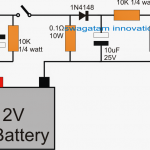
All diodes are 1N4148
Rest of the info is given in the diagram.


Questions & Answers
Please sir, For 9V hi-watt battery
What formula can I used to calculate the battery run time on DC loads.
If the battery is 500mAh, and my load amperage is 20mA and my load power is 200mW. Please sir, what would be the battery run time on idea situation and in practice when 10 – 15% discharge rate is considered?
Thank you
Godfrey, you can get an approximate answer through this software, the formula is also given in the same article:
https://www.homemade-circuits.com/battery-back-up-time-calculator/