In this article we investigate 4 simple yet powerful battery desulfator circuits, which can be used to effectively remove and prevent desulfation in lead acid batteries. The first method uses PWM pulses from a 555 PWM circuit, the second method implements an ordinary bridge rectifier for implementing a 100 Hz frequency based desulfation, the 3rd concept involves high voltage spikes, while the fourth design discusses desulfation using a 555 IC based high amplitude current pulsed circuit.
Sulphation in lead acid batteries is quite common and a big problem because the process completely hampers the efficiency of the battery. Charging a lead acid battery through PWM method is said to initiate desulfation, helping recover battery efficiency to some levels.
What is Sulphation in Lead Acid Batteries
Sulphation is a process where the sulfuric acid present inside lead acid batteries react with the plates overtime to form layers of white powder like substance over the plates.
This layer deposit seriously deteriorates the chemical actions inside the battery while charging or discharging making the battery inefficient with its power delivering capabilities.
Normally this happens when the battery is not being used for long periods and the charging, discharging processes are not done very frequently.
Unfortunately there's no effective way of tackling this problem, however it has been researched that the jammed sulphur deposits over an effected battery may be broken down to some extent by subjecting the battery to high current bursts while charging it.
These high current charging pulses should be well optimized through some control circuit and should be diagnosed carefully while implementing the process.
1) Using PWM
Implementing the method through PWM controlled circuit is probably the best way of doing it.
Here's an excerpt from wikipedia, which says,
" Desulfation is achieved by high current pulses produced between the terminals of the battery. This technique, also called pulse conditioning, breaks down the sulfate crystals that are formed on the battery plates. Short high current pulses tend to work best. Electronic circuits are used to regulate the pulses of different widths and frequency of high current pulses. These can also be used to automate the process since it takes a long period of time to desulfate a battery fully."
https://en.wikipedia.org/wiki/Talk%3ABattery_regenerator
The circuit of a PWM battery charger discussed here can be considered as the best design for carrying out the above desulfation process.
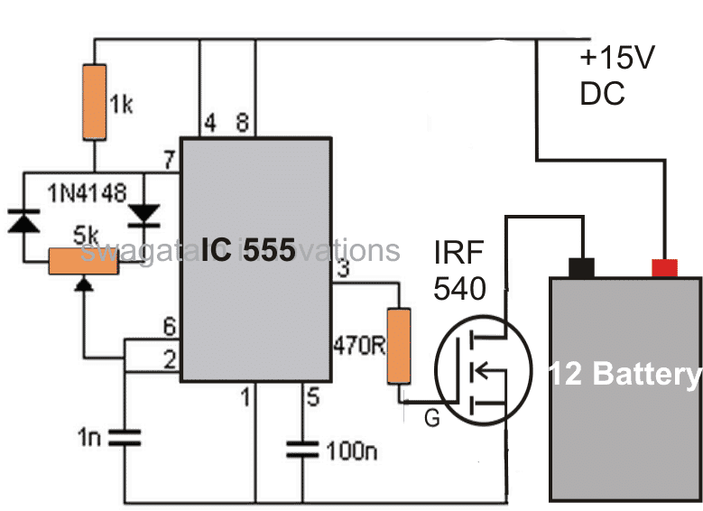
How the Circuit Functions
The IC 555 is configured and used in its standard PWM control mode.
The output from the IC is appropriately amplified through a couple transistors so that it is able to deliver the said high current pulses to the battery which needs to be desulfated.
The PWM control may be set at low "mark" ratio for implementing a desulfation process.
Conversely if the circuit is intended to be used for charging normal batteries, the PWM control may be adjusted for generating pulses with equal mark/space ratios or as per the desired specs.
The controlling of the PWM will solely depend on an individuals personal preference, so should be done correctly as per the battery manufacturers instructions.
Failing to follow the correct procedures may lead to fatal accidents with the battery, due to a possible explosion of the battery.
An input current level equal to the battery AH level may be chosen initially, and reduced gradually if a positive response is detected from the battery.
Important Calculations
Frequency of the 555 Timer
We can see that the circuit operates in astable mode. The frequency is determined by the resistors and diodes connected to pins 6, 7, and 8, along with the timing capacitor.
Formula for Frequency:
f = 1.44 / ((R1 + 2 * R2) * C)
R1 = 1 kΩ
R2: Resistance of the 5k potentiometer adjusted along with the diodes
C = 1 nF (1 nF = 10-9 F)
Duty Cycle Calculation:
The diode configuration alters the charging and discharging paths.
Charging time (ton):
ton = 0.693 * (R1 + R2) * C
Discharging time (toff):
toff = 0.693 * R2 * C
Duty cycle (D):
D = (ton / (ton + toff)) * 100%
Gate Resistor (470Ω)
The 470Ω resistor limits the inrush current to the MOSFET's gate and prevents high-frequency ringing.
Gate charging time constant:
τg = Rg * Cgs
Where:
Rg = 470 Ω (gate resistor)
Cgs: Input capacitance of IRF540 (from datasheet, typical value ~1.2 nF)
IRF540 MOSFET
The MOSFET switches the high-frequency pulses to the battery. Its maximum current and voltage ratings must be selected to be higher than the load.
Power Dissipation:
P = I2 * RDS(on)
Where:
I: Current through the MOSFET (depends on the battery and load)
RDS(on): On-resistance of the MOSFET (typical value ~44 mΩ for IRF540)
Desulfation Pulse
The high-frequency pulse applied to the battery helps to break down the lead sulfate crystals. The frequency and amplitude are the critical aspects for the effective desulfation.
Pulse Voltage:
The pulse amplitude is approximately the supply voltage (15V DC) minus the MOSFETs VDS(on).
Pulse Current:
The peak current will depend on the battery internal resistance and the pulse width.
Capacitors (100nF and 1nF)
100nF (Pin 5): This capacitor Stabilizes the control voltage of the 555 timer and filters noise.
1nF (Timing): This capacitor determines the frequency with R1 and R2.
Notes:
You must choose or measure R2 (adjust the potentiometer for desired pulse frequency).
You can calculate the frequency and duty cycle using the above formulas.
Make sure to verify the MOSFETs current and power ratings against the load.
You can adjust the pulse frequency for the best desulfation results in the range of typically 1–10 kHz...
2) Desulfating with a Transformer and Bridge Rectifier Circuit
To make this simplest yet effective battery desulfator with charger circuit you would just require a suitably rated transformer, and a bridge rectifier. The design not only desulfates a battery, it keeps the new batteries from developing this issue and simultaneously charges them to the desired levels.
At the beginning of this post I have explained how to desulfate using PWM concept, however a deeper research shows that the process of desulfating a battery may not necessarily require a precision PWM circuit, the supply just needs to be oscillating at some given rate, and that's enough to initiate the desulfating process (in most cases)... provided the battery is still within the curing range and is not beyond the reviving state.
So what would you need to make this super simple battery desulfator circuit which will also charge the given battery, and additionally possess the ability to keep the new batteries from developing the sulfation issue?
A suitably rated transformer, a bridge rectifier and an ammeter are all that's needed for the purpose.
The transformer voltage must be rated approximately 25% more than the battery voltage rating, that is for a 12V battery a 15 to 16V supply may be used across the battery terminals.
The current can be approximately equal to the Ah rating of the battery for those which need to be revived and are badly sulfated, for the good batteries the charging current could be around 1/10th or 2/10th of their Ah rating. The bridge rectifier must be rated according to the specified or calculated charging levels.
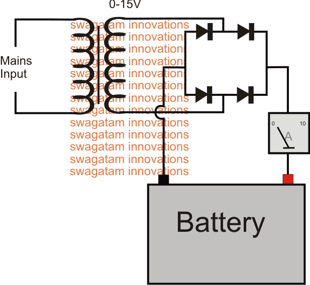
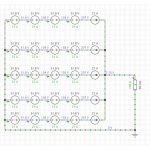
Desulfator Schematic using Bridge Rectifier
How Bridge Rectifier Operates as a Desulfator
The diagram above shows the bare minimum requirement for the proposed battery desulfator with charger circuit.
We can see the most standard or rather crude AC to DC power supply set up, where the transformer steps down the mains voltage to 15V AC for the specified 12V battery.
Before it can reach the battery terminals, the 15V AC goes through the rectification process through the attached bridge rectifier module and gets converted into a full-wave 15V DC.
With a 220V mains input, the frequency before the bridge would be 50Hz (standard grid spec), and after rectification this is supposed to become double that is at 100Hz. For a 110V AC input this would be around 120Hz.
This happens because the bridge network inverts the lower half cycles of the stepped down AC and combines it with the upper half cycles, to finally produce a 100Hz or 120 Hz pulsating DC.
It is this pulsating DC which becomes responsible for shaking-up or knocking down the sulfate deposits on the internal plates of the particular battery.
For a good battery this 100 Hz pulsed charging supply ensures that the sulfation ceases to occur on the first place and thus helps to keep the plates relatively free from this issue.
You can also see an ammeter connected in series with the supply input, it provides a direct indication of he current consumption by the battery and provides a "LIVE update" of the charging procedure, and whether or not anything positive might be happening.
For good batteries this will provide the start to finish info regarding the charging process, that is initially the needle of the meter will indicate the specified charging rate by the battery and may be gradually expected to drop down to the zero mark, and that's when the charging supply needs to be disconnected.
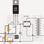
A more sophisticated approach can be employed for enabling an automatic cut-off once the battery is fully charge by employing an opamp based automatic battery full charge cut off circuit (the second diagram).
3) Using High Voltage Pulse
The configuration detailed below provides the most up-to-date methods of desulfating lead-acid batteries. It is a circuit which routinely supplies quick yet intense pulses to the battery, while discharging the battery marginally between the pulses.
This technique, as much as recognized right now, is the best way to knock of undesirable build up of sulphate crystals and to bring back the battery plates into a good condition.
Because the voltage necessary for the high voltage pulses comes from the battery itself (this might appear a little bizarre initially, however the discharge of the battery is likewise a part of this technique), it is advised to hook up a charger in parallel with the battery and desulfator once the battery has not much capacity remaining.
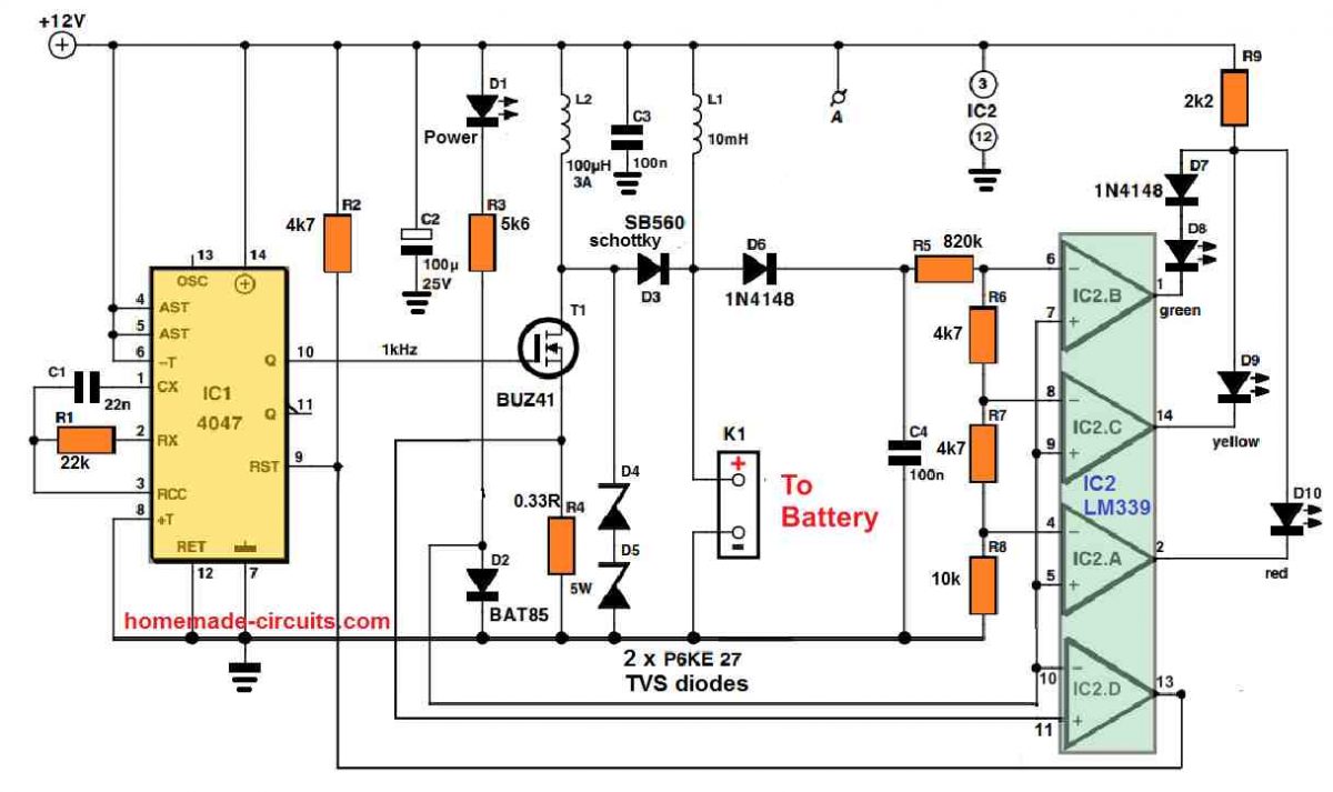
Pulse generator
It could be noticed in the circuit diagram that the parts needed for the desulphator tend to be extremely humble. The circuit consists of a couple of stages: a high voltage generator constructed using IC1, IC2d and T1, that generates the charging pulses, and an indicator circuit which involves not more than 3 op amps (IC2a, b, c) and three LEDs, that indicate exactly what condition the battery is in.
Let’s go through the pulse generator initially. Just like the other parts of the circuit, its supply voltage is obtained from the battery itself through K1. Although we’re discussing the supply voltage, this must have a pretty consistent voltage and should be devoid of any spikes (except those produced by the circuit itself).
Inductor L1 works like a suppressor, and is included in order to eliminate undesirable voltage spikes, along with C2 and C3 which work like smoothing capacitors.
LED D1 illuminates as soon as the supply voltage is switched ON. To proceed with the pulse generator, IC1 (a 4047) produces a square wave having a frequency of 1 kHz and a duty cycle which typically is 50 PERCENT. When the Q output of IC1 turns high, FET T1 switches ON. This results in a (discharge) current to move through the battery by means of L2, that boosts linearly until the voltage across R4 is approximately 0.35 V; the current can now be around 1 A.
At this instant comparator IC2d changes state, triggering IC1 to be reset and T1 to become switched off. The stashed magnetic energy inside L2 now gets converted to a voltage spike, which is inflicted to the battery through D3. How big the spike is can be determined by the condition of the battery.
If the battery is in a decent condition and its internal resistance is rather small, in that case the spike voltage level may also be reduced (under 15 V). In case the battery has a high internal resistance then the peak level of the spike could be as huge as 50 V. Its highest magnitude will be restricted and equal to the value of the two series connected zener diodes, D4 and D5.
LED Indicators
Considering that the health of the battery could be dependent on how big the charging pulses are, we have included a straightforward LED circuit which indicates the optimum value of the pulses. The 3 comparators IC2a-c evaluate the peak value inside C4 and changeover at voltages of 15, 20 and 30 V correspondingly.
Therefore in case the battery is in a reasonably good shape, the green LED (D8) illuminates, with a under-performing battery, the yellow LED (D9) lights up, and with an incredibly bad battery the red LED (D10) glows.
We have an information that needs to be pointed out regarding the indicator circuit: in order to prevent all three LEDs from illuminating simultaneously in response to a high peak voltage, they are attached in parallel to a single common series resistor (R9).
Since the red LED carries a smaller voltage drop compared to yellow LED, they may in no way illuminate together. But the yellow and green LEDs have got a identical voltage drop, so a similar technique will not do the job here, which explains why the green LED comes with an normal diode (D7), hooked up in series with it.
You will find three alternative methods through which the desulfator may be used. The first is to apply it within an existing system (inside a car as an example) to avoid sulphation from taking place inside a battery having minimum sulphation.
The advanced desulfator circuit is built-in with the system by hooking it up straight to the battery using shortest possible cabling. Because the circuit could be kept connected forever, absolutely nothing more needs to be done.
The current consumption is approximately 20 mA, therefore the battery might discharge in case it is not charged up from time to time. Recovery of batteries which have previously sulphated can be carried out in a couple of techniques. The first method would be to charge the battery, eliminate the charger and after that hook up the desulfator circuit.
Since the power for the charging pulses is derived directly from the battery itself, it is going to gradually discharge. This technique needs to be observed carefully because a completely discharged battery must be recharged quickly.
Most likely in real life many charge/discharge cycles will probably be necessary before a terribly sulphated battery could be restored to life. Since the approach described above needs a great deal of attention and has a danger that the battery could be left in a discharged condition unnecessarily (which can be extremely harmful to a lead acid battery!), another method can be perhaps much better.
The battery is coupled to the desulfator circuit, using a trickle charger hooked up in parallel. This implies, no chargers must be integrated that supply a current of 7 A or higher, yet one that provides a optimum of 1 or 2 A. This could be left coupled to the battery endlessly with no issues.
4) Using High Amplitude Pulsed Current from 555 Boost Circuit
We are not going to offer you a solution that will magically solve all the problems with lead batteries. However, the battery desulfator that we will describe in the following lines has proven its effectiveness, mainly in the United States for now, and the measurements we have been able to make on our model have been very promising. As it costs less than twenty euros, which is negligible compared to the price of a new high-quality battery, why not try it out and see for yourself?
Understanding Battery Chemistry
As you may know, a lead-acid battery involves a chemical reaction that can be written as follows during the discharge process:
Pb + 2H2SO4 + PbO2 -> PbSO4 + 2H2O + PbSO4
In other words, the porous lead of one electrode and the porous lead dioxide of the other are transformed, in contact with sulfuric acid, into lead sulfate and water.
Conversely, during charging, the chemical reaction that occurs is as follows:
PbSO4 + 2H2O + PbSO4 -> Pb + 2H2SO4 + PbO2
In other words, lead sulfate and water are transformed, under the effect of electric current, into lead, lead dioxide, and sulfuric acid.
The reaction is theoretically perfectly reversible, and that is why a battery of this type can be charged and discharged many times.
Unfortunately, over time and especially due to incomplete or poorly done recharges, the "reverse" reaction, i.e., the one that transforms lead sulfate into lead, is incomplete and leaves lead sulfate present on the surface of the battery electrodes or plates.
The phenomenon is unfortunately cumulative because, as this lead sulfate is a poor conductor, it tends to thicken where it has started to deposit, which only worsens the problem.
When the sulfation of a battery has reached a sufficient level, no traditional recharge process can overcome it.
Indeed, due to the poor conductivity of lead sulfate, the internal resistance of the battery increases, reducing its charging current and therefore the effectiveness of the charging chemical reaction, leaving even more lead sulfate present on the electrodes.
The resistance of the battery eventually becomes so high that it cannot hold a charge, meaning it can no longer supply significant current due to its excessively high internal resistance.
The Working Concept
This phenomenon has been known for a long time, and there is a chemical process that can be used to eliminate lead sulfate from a battery before it's too late.
However, it's delicate to implement and relatively dangerous due to the chemicals involved. In fact, the battery must be emptied of its electrolyte (corrosive!) to fill it with the cleaning product (also corrosive), and once this operation is complete, the battery must be refilled with fresh electrolyte.
The approach we propose is different and comes from various studies conducted in the United States on the influence of high-amplitude pulsed currents applied to a lead-acid battery.
According to these studies, and provided that very brief but high-amplitude impulses are applied to the battery, the lead sulfate crystals would gradually be broken down by the resulting ionic agitation occurring at the level of the plates and electrolyte of the battery.
This phenomenon is very slow, but since it can be achieved by simple electrical means, this process doesn't pose any particular problems as no manipulation is necessary on the battery being treated.
Circuit Description
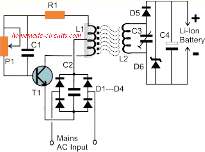
The diagram that we propose is widespread on the internet on the other side of the Atlantic and, as far as we could verify, is attributed to Alastair Ocup. As you can see from in the following figure, it is relatively simple and has many similarities with a boost-type switching power supply.
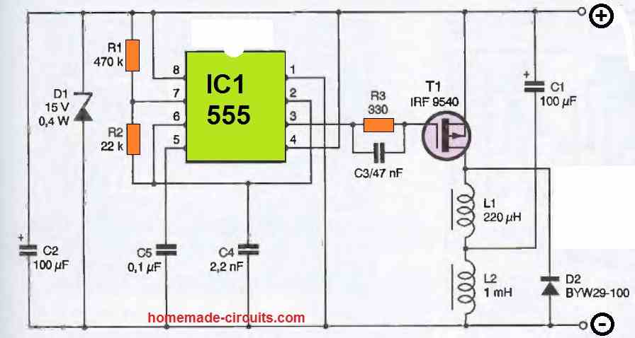
IC, which is nothing other than a classic 555, is configured as an astable oscillator operating at a frequency of around kHz. It produces very short duration pulses on its output available at pin 3.
When the level of these pulses blocks T1, capacitor C1 charges to the value of the battery voltage via inductor L2.
When T1 is made conductive, which only lasts for a brief moment due to the duty cycle of the pulses produced by IC1, capacitor C1 discharges abruptly across T1 and L1 since it is almost short-circuited by these components.
As soon as T1 is blocked again, the current generated by this discharge cannot abruptly cancel due to the presence of inductor L1. It is therefore sent to the battery via diode D2.
If capacitor C1 is of good quality and if the connection between the circuit and the battery is short and made of a suitable diameter wire, a current peak of the order of 5 to 10A can be obtained with a moderately sulfated battery.
Given the operating frequency of the 555 and the duty cycle of the signals it produces, the circuit's consumption remains relatively low and does not exceed an average value of 40mA
Questions & Answers
Hello sir..
i have 13 plate tubular battery 180ah 4 years old only + cell side of the battery is sulfated can i use 555 circuit to de-sulfate it?
sorry for my english..
can you guide me how much amp and voltage and frequency to achieve good results ?
Hi Happie,
Yes you can try the last 555 based circuit. Make sure to increase the C1 value to 470uF/100V or 1000uF/100V and use 2mm thick wire for the inductor…
hai pak
saya sedang melakukan experimen desulfator baterai SLA, menggunakan 555 apakah saya perlu menambahkan pengaturan frekuensi pada rangkaian berbasis 555, agar dapat menyesuaikan keadaan sulfasi baterai yang berbeda-beda
Hi Mahmud, yes you can add a frequency adjust pot to experiment with different battery conditions…
one more question which one is power inductor ?
L1 L2 ? or both need to wind with thick copper wire ?
L1 is the power inductor according to me, but I would recommend using 1mm wire for both the inductors…
This takes too much time, but progress is noted. Is there any other desulfator that powerfully knocks out sulfate crystals and reduce sulphation
Thanks for the feedback…desulfation process will be always slow, ….and it is always, slower the better…
PLS CONTACT MIERAJ 9920233666 WE WANT TO BUILD BLESS CIRCUT DIAGRAM WHICH IS AROUNF 555 IC , WE WANT TO USE IT IN STAND ALONE BATTERY LEAD ACID FLOODED BATTERY,HOW CAN YOU HELP US TO DEGSINE
Yes, I did use a 100uF capacitor instead of the 100nF one and is connected between P1 and P2 and now it measures 165.5kHz
You must change the 1nF at pin6/2 to higher value for testing the frequency.
And please reply to the same thread, otherwise it becomes difficult to track the question…
I had suggested this circuit, there’s no P1, P2 in this diagram. Replace the 1nF with 100uF and check the pin#3 with LED/1k to verify if your circuit is oscillating or not.

Please connect an LED + 1k at the 555 output and check its response, by changing the capacitor value to 100uF…that will tell you whether the 555 oscillating or not…
But I get 10V as my output that goes into the battery. Isn’t that harmful for the battery itself, provided the battery (4V 0.5Ah lead-acid) charger only provides 4.8V 150mA
If your supply voltage is 12V, then with PWM ON the DC output should be much less than 10V, maybe around 5V.
How are you measuring the output voltage?
The 12V will be in short bursts of pulses, not continuous 12V DC.
• How long do I need to leave the battery for to reduce sulphation in it?
• Should I get ~ 5kHz as the output?
• Should I also have ~2V at the output (Input 12V)?
• Which voltage is the best to use in the range of 6-12V?
All these will need to be monitored and experimented by trial and error until the most optimal value is found…
Hello Swagatam
As I understand, desulfation is based on applying pulses of higher than 2.45 volts to each cell.
Can “SLA (sealed lead acid) batteries” be desulfated in this way without reducing their electrolyte?
Hi SA,
Yes, but still it will require some trial and error experimentation, until the right specifications are attained.
According to me SLA batteries can be also desulfated.
It is not a matter of right specifications. The matter is that applying higher than 2.3 volts to a fully charged lead-acid cell will cause it to gas. Because SLA (sealed lead acid) batteries are sealed, their electrolyte cannot be added after gassing.
What do exactly mean by “SLA batteries can be also desulfated”? Do you mean that you experimented one of the above desulfation methods on “SLA batteries” and you observed that their electrolyte did not reduced?
When any battery gets sulfated that means it is almost dead and inactive, so to revive it we have to test through some trial and error method until the right PWM, voltage and current specifications are know….we can do this through a series meter connected.
Narrower PWM is better, but you will have to test and verify the results practically.
What is the 5k pot for? And can I replace it with a 4.7k pot if it is necessary
The 5k pot is for pulse width control, you can use 4.7k, or 10k, or 22k…
Try the 1st 555 circuit, use 6V to 12v as the input.
Can you make a desulfator circuit for a 4V lead-acid battery??
You can use the last circuit design…
Good evening Sir
I am an undergraduate student and I am having a bit of difficulty as to selecting a project topic for my mini project. I came across your website in the process of searching and wondered if you could be of help to me. My project has to involve a transformer and a rectifier and I dont want it to involve anything that has to do with smart detection or IoT. I await a positive response. Thank you for your cooperation
Hi Chizulum,
If your project needs to involve a transformer and a rectifier, that means it can be simply a standard transformer based power supply…you can try any one of these circuits, as explained in the following article:
https://www.homemade-circuits.com/how-to-design-power-supply-simplest-to/
hi Swag
how is the desulphation circut by AListair ocup powered if battery to be desulphated is flat
Hi Wayne,
It is difficult to judge if a flat battery would respond to a desulphation pulses, it will depend on the age and internal condition of the battery. Only a practical test could tell us if that’s possible or not.
In that case the bridge rectifier based design looks more effective to me…since it can deliver higher amounts of current.
I need a lead acid battery Desulfator complate cirkit. need things price .
Please can I use 150hz battery charger to charge lithium battery?
Do you mean charging the battery with a 150Hz frequency? Yes, that’s possible, but Li-ion batts don’t have sulfation problem I guess?
Yes to charge, won’t it affect the battery or cause fire
150 Hz won’t cause any harm to your battery, you can use it according to me, although it is not required. You should use a constant DC instead.
Thanks for the information it’s definitely useful.
Please don’t misunderstand but I would like to share some of the methods that I have used which works satisfactorily.
I used a charger that gives 17Volts @5Amp for 150AH Battery. Only important thing is that the caps/indicators have to be kept open because the water inside the battery starts boiling. This boiling water clears the sulphanation and it dissolves internally.
Another method I had used was I removed little acid from the battery. Then I prepared a solution by adding dissolving Epsom salt (Magnesium sulphate) in warm distilled water so that it dissolves quickly. I then top-up this solution to cover up the plates and then kept the battery for charging. This also refreshes the battery.
One more way is to drain out the battery. Pour into it hot boiling water, close the caps, shake well the battery for several times and drain the water. Doing this 3-4 times clears up the sulphanation. Then remove some acid from a healthy battery and add it to this battery and charge it normally. This method is also useful. I have refreshed many SMF batteries also by this method.
Finally one important point to remember is that the internal plates physical condition should also be better. Better meaning not damaged, else no method will work
The information you have provided is extremely valuable, and I hope the other readers will also find it very useful and effective.
Thank you so much for this contribution! It is much appreciated!
Hello, on the third circuit, I’m looking to build it but I don’t have all the exact components. 2 things, Can I replace the mosfet BUZ41 with FQPF4N90C? what are the main requirements for the mosfet? The other thing is the two P6KE 27 TVS diodes in series, can I replace them with SMAJ54? Likewise, in series?
Thank you.
Hi, FQPF4N90C is an ok replacement for BUZ41 if your current spikes does not go over 4 amps and if you use a good heatsink.
SMAJ54 in series will work but it will allow more voltage spike than 2x P6KE27, so it is less safe. Better to use 2x SMAJ27 instead for closer match.
Alright. Thank you.