A DC cell phone or mobile phone charger is a device which charges a cellphone from an available DC supply source. The device converts the unregulated DC source into a constant current and constant voltage output which becomes safe for any mobile phone charging.
In this article I have explained how to build DC to DC cell phone charger circuits using 6 unique concepts. The first concept concept uses the IC 7805, the second concept works with a single BJT, the third idea uses a IC M2575, in the fourth method we try LM338 IC, the 5th circuit shows how to charge multiple mobiles from a single source while the last or the 6th technique shows us how to use PWM for implementing an effective charging of a mobile phone.
Warning: Although the concepts are all tested and technically correct, the author does not take any responsibility of the results, please do it at your own risk.
Introduction
A simple DC cell phone charger circuit is one of those mates of cell phone that cannot be ignored because a cell phone would be dead without a charger.
Normally a DC cell phone charger circuit come as an integral part of a cell phone package and we use it in conjunction with our AC mains supply.
But what happens if your cell phone gasps for power in the middle of a journey, probably when you are driving or biking away on a middle of a highway?
How it Functions
A very simple yet reasonably effective DC to DC cell phone charger circuit is discussed in this article, which can be easily built at home even by a layman.
Though the proposed charger circuit won't charge your cell phone at the rate equal to a normal AC to DC charger, nevertheless it will complete the function without fail and won't betray you for sure.
The proposed DC cellphone charger circuit can be understood with the following points:
We all know the general specs of a cell phone battery, it's around 3.7 volts and 800 mAH.
It means the cell phone would require at around 4.5 volts for initiating the charging process.
However a Li-Ion battery which is employed inside cell phones are pretty sensitive to bad voltages and may just blow off causing serious life and property issues.
Keeping this in mind the cell phone internal circuitry is specifically dimensioned very strictly.
The parameters just won't permit any voltage which may be even slightly out of the range of the battery specifications.
The use of the versatile IC 7805 in the circuit answers the above issue just perfectly, such that the charging voltage at its output becomes ideally suitable for charging the cell phone battery.
A high wattage resistor connected at the output of the IC makes sure that the current to the cell phone stays well within the specified range, though this might have not been a problem anyway, the cell phone would just refuse to charge if the resistor was not included.
1) Circuit Diagram of the DC cellphone charger
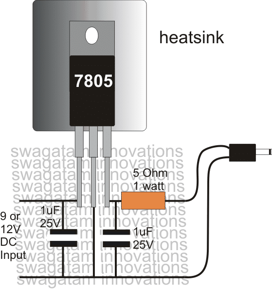
Pictorial Diagram
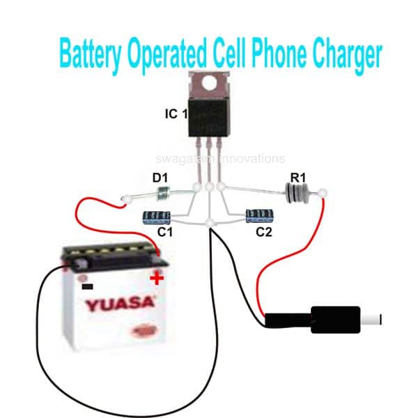
You can use this DC cellphone charger circuit for charging you cell phone during emergencies when there's no mains AC outlets, the circuit may be powered from any 12 volt lead acid battery or similar DC power source
Parts List
R1 = 5 Ohm, 2 Watt,
C1, C2 = 10uF/ 25V,
D1 = 1N4007,
IC1 = 7805, mounted on a heatsink,
Battery, any 12 volt automobile battery
Using LM123/LM323
In the above concept a 7805 IC is used for charging, which can deliver a maximum of 1 amp. This current may not sufficient enough for charging smart phones, or cellphones with bigger mAH rating in the range of 4000 mAh. Since these high current batteries may require current up to 3 amps for charging at reasonably fast rate.
A 7805 might be completely useless for such applications.
However, the IC LM123 is one candidate which can fulfill the above requirement, by providing a precision 5 V output with a good 3 amp current. The input can be from any 12 V source such a car/motorcycle battery, or a solar panel. The simple 3 amp mobile phone charger diagram can be seen below:
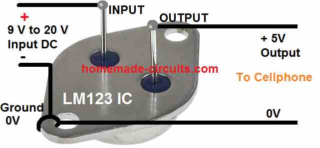
As can be seen above the 3 amp charger circuit requires no external components for implementing the procedures, and yet is extremely precise with its output voltage and current regulation, and is virtually nondestructive due to it many internal protection features.
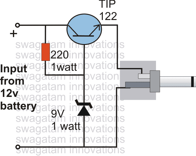
2) DC Cell phone Charger using a Single Transistor
The next design explains a DC cell phone charger using a single BJT is probably the simplest in its forms and may be built very cheaply and used for charging any standard cell phone from a DC 12 volts external source.
Circuit Operation
The circuit diagram illustrates a rather straightforward design incorporating very few components for implementing the proposed cell phone charging actions.
Here the main active part is an ordinary power transistor which has been configured with another active part, the zenet diode for forming a nice little DC to DC cell phone charger circuit.
The resistor is the only passive component other than the above couple of active parts which has been associated in the circuit.
So just three component is to be used and a full fledged cell phone charger circuit is ready within minutes.
The resistor acts as the biasing component for the transistor and also acts as the "starter" for the transistor.
The zener has been included to inhibit the transistor from conducting more than the specified voltage determined by the zener voltage.
Though, a cell phone ideally requires just 4 volts for initiating the charging process, here the zener voltage and subsequently the output voltage has been fixed at 9V, because the current releasing ability of this circuit is not very efficient and presumably the power should be dropping to the required 4v level once the cell phone is connected at the output.
However the current may be decreased or increased by suitably increasing or decreasing the value of the resistor respectively.
If the cell phone "refuses" to get charged, the resistor value nay be increased a bit or a different higher value may be tried for making the cell phone respond positively.
Kindly note that the circuit was designed by me based on assumptions only and the circuit has not been tested or confirmed practically.
Circuit Diagram
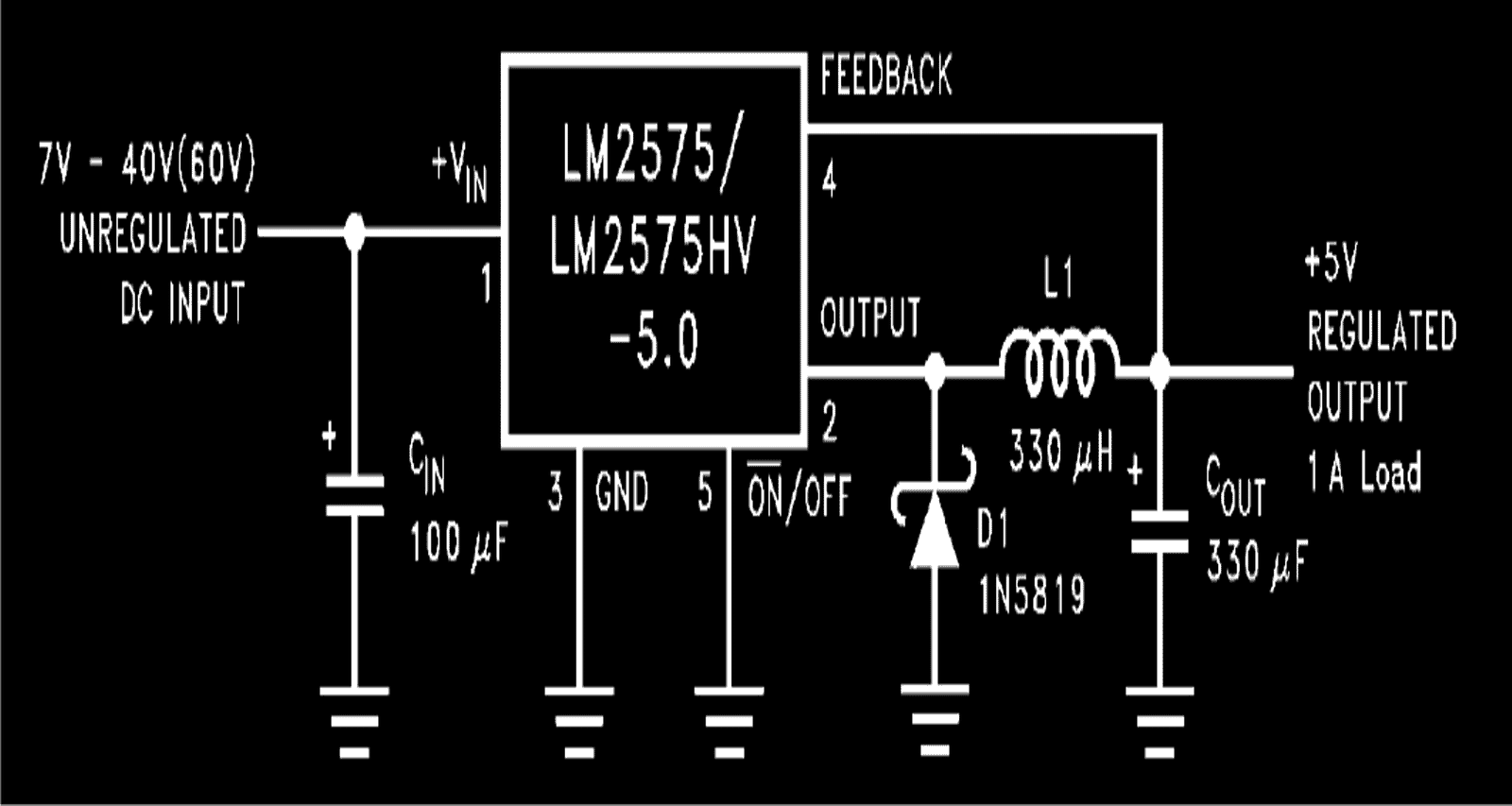
3) Using 1-A Simple Step-Down Switching Voltage Regulator
If you are not satisfied with a linear regulator charger, then you can opt for this 1 A simple step-down switching voltage regulator based DC cell phone charger circuit which works with a switched buck converter principle which enables circuit to charge a cell phone with great efficiency.
How it Works
In one of my previous posts I have explained about the versatile voltage regulator IC LM2575 from TEXAS INSTRUMENTS.
As can be seen, the diagram hardly utilizes any external components for making the circuit functional.
A couple of capacitors a schottky diode and an inductor of all that is needed to make this DC to DC cell phone charger circuit.
The output generates an accurate 5 volts which becomes very much suitable for charging a cell phone.
The input voltage has a wide range, right from 7V to 60V, any level ma be applied which results the required 5 volts at the output.
The inductor is introduced specifically for obtaining a pulsed output at around 52 kHz.
Half of the energy from the inductor is used back for charging the cell phone ensuring that the IC remains switched only for half the charging cycle period.
This keeps the IC cool and keeps it effectively in working even without using a heatsink.
This ensures power saving as well as efficient functioning of the entire unit for the intended application.
The input may be derived from any DC source like an automobile battery.
Courtesy and Original Circuit: ti.com/lit/ds/symlink/lm2575.pdf
4) DC Double Cellphone Charger
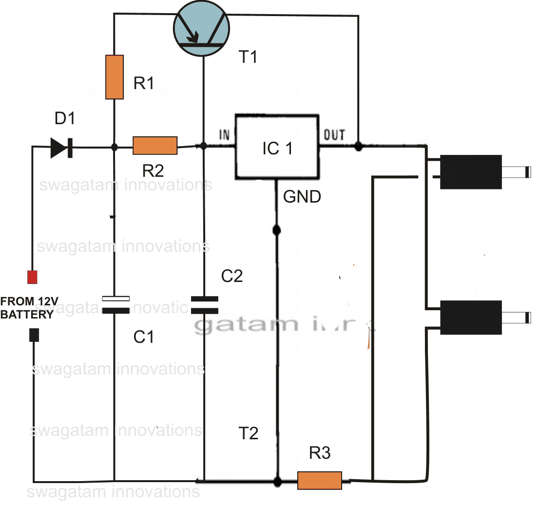
A recent request from one of my followers Mr. Raja Gilse (via email), prompted me to design a DC double cellphone charger circuit that is able to facilitate charging of many cell phones simultaneously, I have explained how to make the circuit.
I have already explained regarding a couple of DC to DC cellphone charging circuits, however all these are designed for charging a single cell phone. For charging more than one cell phone from an external DC source like an automobile battery, requires an elaborate circuit.
Technical Specifications
Dear sir. Please tell me that what alterations should i do, to charge two mobiles at a time from your "12V BATTERY OPERATED CELL PHONE CHARGER CIRCUIT".(from bright hub) I am using the circuit from last 8 months, it's fine. Please post that article in your new blog also.
Dear sir, i tried so many time to post this comment in your blog in the "simple dc to dc cell phone charger circuit" but in vain. Please answer here~ Sir, i used another 10 ohm 2 watt resistor in parallel with the existing one, as i don’t have the higher watt resistor. It’s working fine. Thank you very much, i have one doubt, earlier, in bright hub in the same article you told to use 10 ohm resistor, but here it is 5 ohm which is suitable ?
I have another question out of this article; please guide me could I use three 1N4007 silicon diode instead of one 1N5408 silicon diode? My aim is to allow 3A current in only one direction. But i don’t have diode of 3A i.e. 1N5408. As 1N4007 is of 1 amps capacity could use three 1N4007 in parallel and like wise for 5A five 1N4007 in parallel, because i have number of 1N4007
rajagilse
Solving the Circuit Request
Hi Rajagilse,Use the following DC double cellphone charger circuit given below:
Hi Raja,
As you increase the limiting resistor value, the charging becomes slower, therefore a 5 Ohm resistor would charge the cell phone faster than a 10 Ohm, and so on. I'll check the problem with the commenting in my blog...however other comments are coming normally as usual! Let's see. Thanks and Regards.
Parts List
- R1 = 0.1 Ohms 2 watt,
- R2 = 2 Ohms 2 Watt
- R3 = 3 Ohms 1 watt
- C1 = 100uF/25V
- C2 = 0.1 discT1 = BD140 D1 = 1N5408
- IC1 = 7805
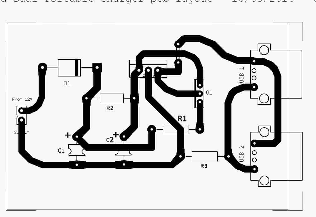
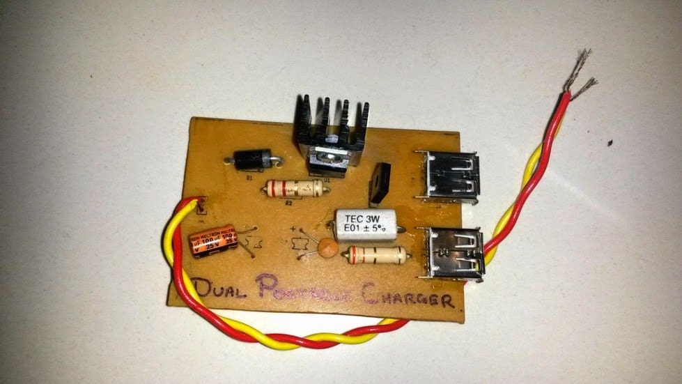
PCB Design
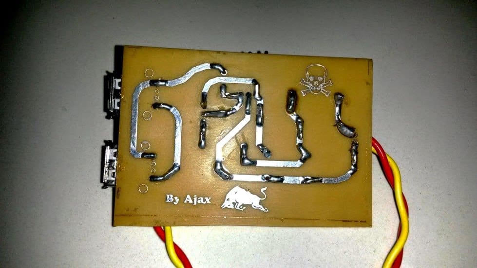
The circuit of the double DC cell phone charger was successfully tried and built by Mr. Ajay Dussa over a home designed PCB, the following images of the PCB layout and the prototype were sent by Mr. Ajay.
5) LM338 Based Cell Phone Charger Circuit
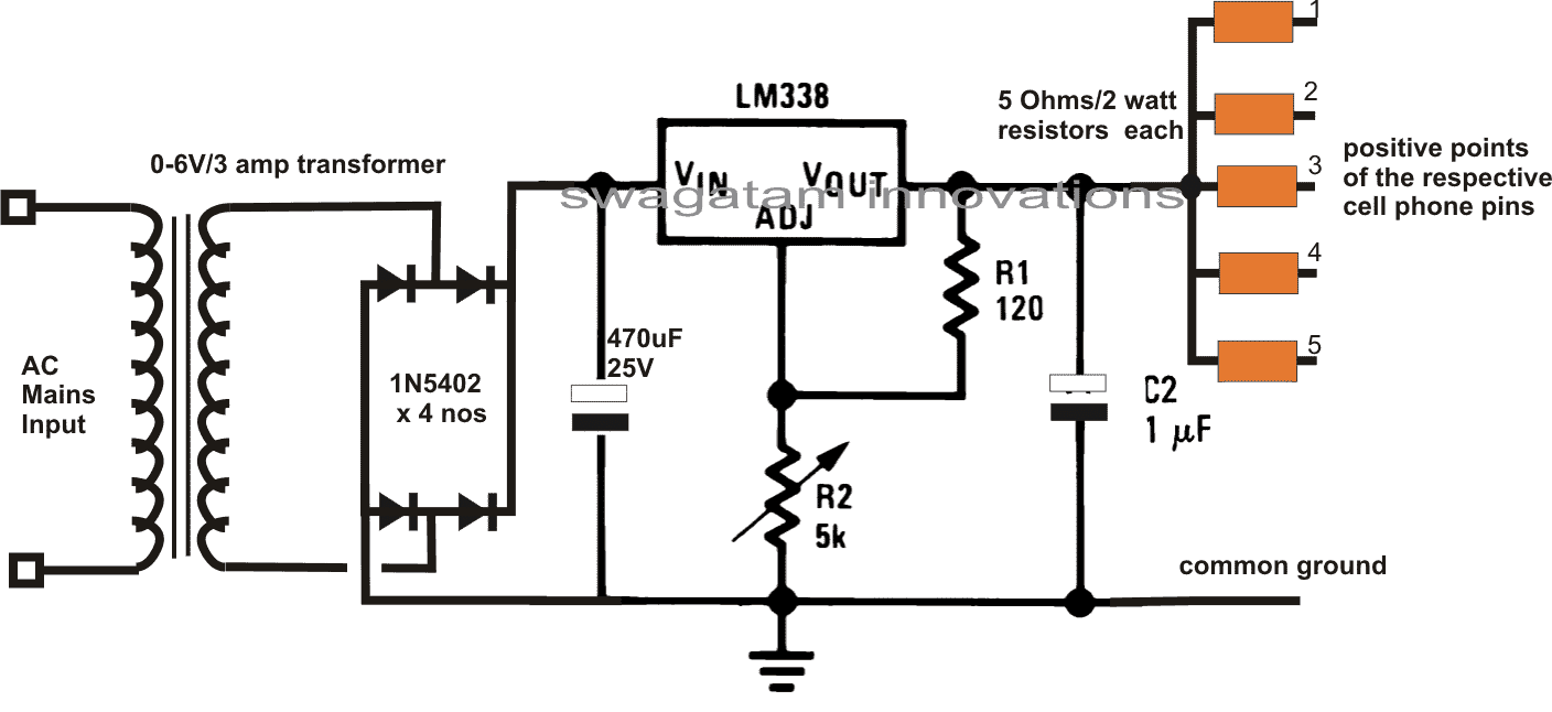
The following circuit can be used for charging as many as 5 cell phones at a time. The circuit employs the versatile IC LM338 for producing the required power. The input is selected to be a 6V but can be as high as 24V. A single cell phone can also be charged from this circuit.
The circuit was requested by Mr. Ram.
Multiple Cellphone Charger Circuit using IC 7805
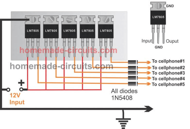
Any desired number of cellphones can be charged by using IC 7805 in parallel as shown the following figure. Since the ICs are all mounted on the same heatsink the heat among them is uniformly shared ensuring a uniform charging across all the connected multiple cellphone devices.
Here 5 ICs are used for charging by medium sized cellphones, more number of ICs could added to accommodate more number of cellphones in the charging array.
6) Using PWM For Charging Cellphone Battery
This circuit can be easily made at home by any school kid and used for displaying in his science fair exhibition. The circuit is a simple cell phone charger that may be operated in conjunction with any DC source, from a car or a motorcycle battery or from any ordinary 12 V AC DC adapter.
Nowadays we find most of the vehicles have their in built cell phone battery charger units which surely becomes very handy for travelers who mostly remain outdoors travelling in their vehicle.
The proposed cell phone charger circuit is as good as the conventional chargers which come fitted inside the cars and bikes.
Moreover the circuit can be simply integrated to ones own vehicle if the feature is not originally available in the vehicle.
Alternatively one may think of manufacturing the present unit and selling them in the market as an automobile cell phone charger and earn some hard bucks.
Circuit Operation
Cell phones as we all know are highly sophisticated gadgets by nature and when it comes to charging cell phones the parameters no doubt also needs to be of very high standards.
The AC/DC cell phone chargers which come with the cell phones are all SMPS based and are extremely good with their outputs and that’s why the cell phone gets so efficiently charged by them.
However if we try to make our own version, it may fail altogether and the cell phones may just not respond to the current and display a “not charging” on the screen.
Cell phone battery cannot just be charged by supplying DC 4 volts, unless the current is optimally dimensioned the charging won’t initiate.
PWM vs Linear
Using voltage regulator IC for making a DC to DC charger, which I have discussed in one of my earlier article is a good approach, but the IC tends to become too hot while charging the cell phone battery and therefore requires adequate heatsinking for remaining cool and operative.
This makes the unit a bit bulkier and moreover some significant amount of power is wasted in the form of heat, so the design cannot be considered very efficient.
The present PWM controlled DC to DC cell phone charger circuit is outstanding in its respect because, the involvement of PWM pulses helps to keep the output very suitable to the cell phone circuitry and also the concept involves no heating of the output device, making the entire circuit truly efficient.
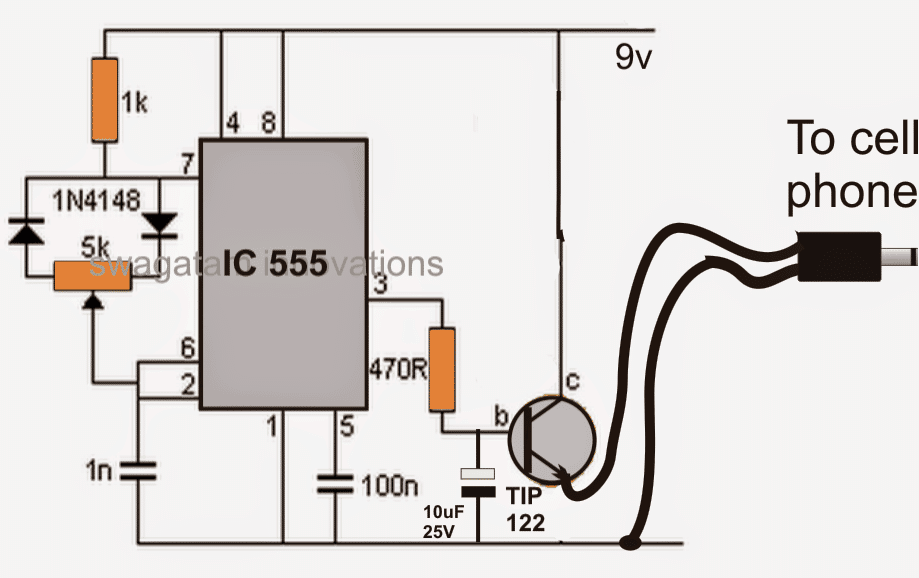
Looking at the circuit we find that again the work horse IC 555 comes to our rescue and performs the important function of generating the required PWM pulses.
The input to the circuit is supplied through some standard DC source, ideally from an automobile battery.
The voltage powers the IC which instantly starts generating the PWM pulses and feeds it to the components connected at its output pin #3.
At the output the power transistor is used for switching the DC voltage at its collector directly to the cell phone.
However only the average DC voltage is finally fed to the cell phone due to the presence of the 10uF capacitor, which effectively filters the pulsating current and provides a stable, standard 4 volts to the cell phone.
After the circuit is built, the given pot will need to be optimized perfectly so that a well dimensioned voltage is produced at the output which may be ideally suited for charging the cell phone.
Circuit Diagram



Questions & Answers
diode is placed only for safeguarding the circuit from accidental reverse input connection. You can remove it but be sure you connect the input polarity correctly then.
thanks sir
sir can you tell me how much time required for charging a mobile???
& sir i have project about bicycle dynamo. sir if you don't mind can you send me an easy diagram to make bicycle dynamo/bicycle generator??
2 to 3 hours will be required.
you can connect the dynamo output to the above circuit via a bridge rectifier stage and start charging the cell phone as explained above.
it help me alot.THANKS SIR…
sir app bta skte ha k ak battery ktne dair run kr skti haa??
i mentioned it in the previous comment, 2 to 3 hours.
welldone you are great sir you can done this job I have learned a lot from this can i get your number please give me whatsapp number
Thank you Zohaib, you can discuss your queries through comments here, I will try to help!
sir can i connect this circuit with motorbike battery and car battery??
if yes ,so will there any problem of input & outout current because automobile battery's current is very high??
i know voltage is not a problem.. what about current.
THANKS FOR YOUR ALL PREVIOUS HELP SIR…..
As long as the input voltage is within 24V, current will not mater, so you can use it freely with your motorcycle battery also.
THANKS SIRRR
THANK YOU…!!!
sir please tell me if you have any knowledge about any softwere about circuit designing in which bicycle dynamo ,d.c motor or other mechanical equipments present????
No, sorry I don't have any such software.
you can use the same circuit which is shown above.
Hello Omar, just replace the 7805 with a LM123 and it will become suitable for the required application.
sir,this condition ok…the 12v continuously going at 7805 and step down to 3v…normally example you take mobile charger,u have charging mobile, charging and the battery is full….and automatically disconnect the charger….
in this project,only charging the battery not getting the charge is full condition automatically disconnect condition..how to get automatically disconnect after the batter full..plz give me the circuit and information………
Dear Sir ,
I would to know , can I use this circuit to power up mobile phone without battery attached.
Thanks in advance.
Nope! the circuit will require an input source, otherwise it won't work
Dear Sir ,
Can i use your diagram to power up my cell phone without attached the battery to the phone?
Thanks
mobile chargers do not have auto shut off feature, rather cell phones have auto cut off feature in-built, therefore it's safe because the cell phone in-built circuit would cut off as soon as its battery gets fully charged.
If it's 4V then it would charge your cell phone when hooked directly, anything less than 4V would make the charging inefficient and sluggish.
You are welcome!
No changes would be required, use the same circuit for 6V input.
yes you can.
can i use mobile charger to start motor?
motor = 0/6.0 v
charger = output – DC 6.0 v
can i use mobile charger to start motor?
motor = 0/6.0 v
charger = output – DC 6.0 v
yes you can
HELLO SIR..
SIR MJHE UNI PROJECT K LIA AK CIRCUIT CHAHEA JISME 2 IC lm714 US HO..SIR PLEASE KOE HOMEMADE PJOJECT KA LINK SEND KR DIJEA..
I WILL BE THANKFUL TO YOUU…………….
Hello Abdul,
You can try the first circuit given in this link:
https://www.homemade-circuits.com/2011/12/how-to-build-electronic-spy-bug-circuit.html
….sorry, the above circuit uses a single 741, try the following one, replace the LM324 opamps with two IC741:
https://www.homemade-circuits.com/2012/04/make-this-simple-motion-detectorsensor.html
Sir, I want to build a cell phone charger which input is 220 V AC. When cell phone charging is completed then charger should be switched off automatically to save / conserve the elctricity. The reason is that when cell phone is charged fully and charger will not switch off automatically. Then two problems occures. One is over charging which can damage the cell phoe circuit. Second charger it self may be burn out. Please provide me full guidance. Thanks
Khan Baig, All cell phones have in-built auto cut off, so the battery will never get over charged. Still if you wish to switch OFF the circuits presented above automatically, to reduce power consumption, I’ll surely do it soon and update the same.
thanks sir.
but I m student of 3rd semester. this schemetic is little bit complex
for me.so sir please send me an easy schematic. so I can make it .
thank u sir for helping me a lot… …
Hi Abdul,
I don't have any simpler circuit than this at the moment, I'll try to find it and tell you soon.
HELLO SIR……..
SIR APNE JO SEND KIA THA LINK ME WOHE BNA RHA HUU..
MENE APKE BLOGES ME RELAY CONNECTION PARHA . KCH SMJH AYA SIRF YH BTA DE AP K JO RELAY KI 5 PINS HA WO KHA KHA CONNECT HA???
N/C & N/O KHA CONNECTED HA:COIL TERMNALS KHA CONNECTED HA??
AUR JO PICTURE ME 12 VOLT K UPAR BLUE LINE HA WO KHA CONNECT HORAE HA.
SIR I HAVE ONLY 3 DAYS TO MAKE IT .
THANKSS…..
The square box named 'relay" is the coil of the relay, among the contacts the upper circle is the N/C and the lower circle is the N/O, the central link is the moving pole of the relay.
THANKS SIR.. YOU CLEARED MY CONCEPTS.
BS MJHE YH BTADE N N/O, N/C & MOVING POLE OF THE RELEY CIRCUIT ME KHA CONNECTED HAIN????AK TO YH RELAY ME CONNECTED HA LEKIN YH CIRCUIT ME KHA CONNECTED HA YH NAE PTA CHAL RAHA..
N/O, N/C and the pole are not connected to the circuit, they are connected to the load or an alarm via AC mains, there's no connection with the circuit.
If you are using a DC alarm then you may connect it with the circuit 12v supply.
ok sirr
sir jo 12 volt dc alarm ha iska koe link send krde. mjhe zehan me idea nae arha..
project bhht acha lga ha mjhe iSlia yhe bnana cha hu.complex ha but i will try my level best.
aur relay ki 3 wire jo alarm se connect HA uska be lnk btade
THANKS SIR…….
sir mjhe dc alarm ka idea nae ho rha. plz send me link about dc alarm. aur is circuit me sensor knsi chez ha jaha se motion indicat hogi aur alarm on hoga
don't make the aarm, buy it from the market, you can use a car musical horn or a 12v musical door bell.
relay connection:
pole to 12V(+), N/O to alarm (+) wire and (-) of alarm to circuit ground or supply negative.
THANKS SIR..
sir yh jo diagram me A1 HA ISKI Pin 1 to led k sth aur pin aur pin 2 potentiometer k sth ha but confusing pont is k pin 1 & pin 2 k bech me se ak point upar 12 volt aur resister k sth node bna rha ha. yh ks pin se nkal k upar ja rha ha.aur sirf A1 KI 3 PIN CONNECTED ha bki kia ground krni ha???
and same question for A2 .usme be pin 5 & 7 connected ha aur bech mese ak wire jake grounded ha.yh knsi wire ha???
SIR IS THERE ANY WAY TO CONNECT WITH YOU & YOUR KNOWLEDGE DIRECTLY????
BECAUSE SOMETIMES I WANT QUICK ANSWERS AND FROM BLOGS, I HAVE TO WAIT 1 DAY. KINDLY TELL ME ANOTHER WAY SO THAT I CONNECT WITH YOU DIRECTLY ..
THAKNS SIR..
It's the supply pins of IC324….positive line goes to pin4 and the ground pin goes to pin11.
I am sorry you can contact only through this blog.
SIR………
datasheetoo.com/datasheet-application/automotive/electronic-siren-circuit-diagram-using-741-op-amp-ic.html
THIS IS ELECTRONIC SIREN . SIR I WANT TO ASK THAT SPEAKER IS PRESENT THERE,WHERE I CONNECTED INPUT SOUND SO SPEAKER CAN AMPLIFY???
THANKSS SIR FOR HELPING ME A LOT…
I did not understand your question, what are you trying to make?
Sir please tell me connection of relay with dc alarm . I am using dc alarm for output.
Secondly, if I want to check the circuit that it is working or not without an alarm, how I check it???
Actually mjhe teacher ko check krwana ha without alarm.
relay connection:
pole to 12V(+), N/O to alarm (+) wire and (-) of alarm to circuit ground or supply negative.
The red leds will be shut off after setting up, and when a motion is detected across any of the LDRs the relevant red LED will light up indicating a motion.
This means sir that N/0 does not use in this circuit.??
And pole se phir 12 volt p connect krna ha?? I can't understand. Please send any diagram from which I understand.
THANKS….
pls read the connections again, N/O is connected to (+) of alarm circuit, N/C is blank, not connected anywhere.
(-) of alarm circuit is connected to supply negative
relay pole is connected to supply positive
I UNDERSTAN SIR..
SIR IN MY CIRCUIT,ONLY ONE LDR IS WORKING ,WHEN I DISCONNECT ONE LDR,OTHER LDR WORK AND OTHER PROBLEN IS THAT IT WORKS IN OPPOSITE FORM MEANS WHEN IT DETECTS ANY MOTION,LED OFF OTHERWISW IT ON ALL THE TIME.
AND SIR TELL ME HOW I SET P1 & P2???
THANKSS….
you may have connected the pinouts wrongly, i have tested this circuit it works superbly.
when correctly set both LEDs will switch off completely and illuminate only when a shadow is detected across any of the LDRs.
I have explained the set up procedures in the article.
sir kindly tell me the connection of potentiometer?? like it's first leg is connected to 10k resister ,i m confused about second & third pin connection.tell me the connections for both , P1 AND P2.
THANKS FOR HELPING ME ALOT..
use the center pin and any one of the other pins, that's all…
center pin is compulsory, the other one can be any of the remaining two.
I have made some changes in the diagram, please do it in your circuit also, it will give better results, and pls comment on motion sensor article, not on this page.
will depend on the AH rating of the battery and the phone.
Ravinder Kumar from Indigenous Home made Tech is here -Dear sir i used u r given circuit (with C1,C2= 10uF/25V )BUT by using diode and resistance does not work ,so i have removed diode and resistance now its charge but not 100% it charges the cell phone only to 70% by using 6volt 4.5Ah Battery ,
Request you please suggest to increase charging efficiency limit to 100% .
I am sorry the above circuit cannot be upgraded any further. You can use an LM338 design and adjust the voltage to suit the cell phone needs. You may refer to the first circuit in this link:
https://www.homemade-circuits.com/2012/04/ic-lm338-application-circuits-explained.html
hello sir!!!!
can u please tell me what is the function of capacitors in the above circuit ???
Hello Danish,
It's there for filtering noise and voltage spikes.
You are welcome, Pukhrambam!
hello sir
sir mujhy 12v bike ki battery sy mujhy 15v out chahey or internet device chalane hai
or woh bhe atomatic yane k lite jae to auto battery per ajae plz plz plz plz plz sir help me…………plz plzp plz.
hello faizan,
make this circuit first for 12v to 15v conversion:
https://www.homemade-circuits.com/2012/09/led-emergency-light-circuit-using-boost.html
then i'll tell you what to do next.
Heloo Dear sir
I like your response and advise and bless you!!
My question is is it good to use 5v,1w solar panel for the above circuit application with out 7805??What about 6v ,1w solar panel with 7805????
Hello Alealu
Thanks!
with a 5V solar panel you don't have to use any IC at the output, you can connect your cell phone directly with the panel via a 5 OHM/ 1 watt resistor….it will start charging.
……same with a 6v panel.
Thank you,and what about the fluctuation of the sun,it cant affect the battery?
bic the output from the sun is not constant,
when you say it's a 5V panel it signifies the peak value at peak sunshine, so technically it cannot exceed this level.
But anyway you can use the above circuit in conjunction with it for better safety.
I mean, even if it is 5v peak this voltage do not exceed 5v but may goth below 5V ,so the voltage may be 5,4,3,2…..v depending up on sunshine,As a resale,is such low voltage is safe for mobile battery life????
Thank you
The cell phone will stop charging once the voltage reaches below 4V.
Lower voltages will not harm the cell phone.
sir meray pas12v 2.5amp dc bttry hy or mujay 9v aor 1amp output ke zarurat hay,,,,plz Circuit Diagram share krday,,,,,
You can use a 7809 IC at the output, it will give you a 9V/1amp output from your 12V battery.
The connections will be same as in the above 7805 design
hello sir.. i have a samsung galaxy duos gt i9082 the battery is 3.8V Li-ion, 2100mAh
can i charge it in my motorcycle using the above circuit?
Hi Jhud, you can do it, but use two 7805 ICs in parallel for getting a better current gain and quicker charging rate. Make sure that both the ICs are mounted on a common heatsink. also reduce R1 to 3 ohms/5 watts
good day sir… i did loved your blog.. bcoz its very usefull here in our place this time becauze we have no electricity… so i did make your circuit but i got an error in my cellphone.., bad contact of charger… i did use 2 10uf, and 5ohms 2 watt.. pls help.. thnx..
thanks charles, try 10 ohms in place of 5 ohms or some higher value and check the result
tnx sir… i'll try as soon as i can buy 10 ohms or higher…
—–
sir, i have here a 9v dc solar panel.. i only get around 5.5v-8v dc (not stable) if its not so sunny… can i still use this circuit?
yes, you can safely use the above circuit with your solar panel.
Hello sir.
Sir I want some help from your side. Sir I have project regarding computers logic design. Topic is:
DESIGN AND IMPLEMENT A CIRCUIT THAT COULD GLOW A LED WHEN 3 OF THE AVAILABLE 7 TANKS NEED A REFILL.
Sir I want circuits or if u have idea, so tell me.
THANKS SIR………
Hello Abdul,
You will have to provide me with full details regarding the application need, only then I would be able to come up with something suitable
HI sir can i use this circuit on my 3.8v 1500mah battery?
yes you can, just reduce the resistor values from the shown 5 ohm to 1 ohm
Helol Abdul,
Where will these tanks be used, what kind of liquid will be used in these tanks?
Dear sir can I use old cellphone batteries as a cellphone power bank if yes then how plz give a simple circuit
sir using different gates,i have to make circuit . there are 7 tanks available,when 3 0f them are empty so led which is connected at output is glow. A combination of gates is using here.what logic is using sir??
hello sir,
sir what if I remove the diode,capacitors and the resistor in the circuit and just connect the wires directly to its places connected to the IC? Will it still work?
hello kazuto, the resistor is compulsory, the capacitors can be removed, and it will still work provided the input is a pure DC
Sir,
Plz tell me how to control 24watt energy sever for remote control.
hello sir can i use 4.7 ohm resistance at output side instead of 5 ohm
and can this circuit charge my android phone also
plzz ur rply is very important for me
yes 4.7 ohms will do.
It will charge your android phone also, the 4.7 ohm may need to be reduced for making the charging a little quicker.
Hi Sir..
Your blog gives a lot of knowledge about charger circuit… thanks for this ideas as will as the circuit you shared to us… i would like to make a 48 v 1+ amp supply, can i use the above circuit with IC??? or what should be the value of R=?,C=? and the IC number=? … thanks a lot Sir…. God Blesses you always…
Thanks Marque,
48v cannot be achieved using fixed voltage regulator ICs, you will have to make a transistor regulator circuit as given in the following post:
https://www.homemade-circuits.com/2012/01/how-to-make-versatile-variable-voltage.html
Sir normally mobile phone charger have lot of components so mobile battery life is well.but in this circuit have simple few components how to trust this and what about mobile battery life after charged this circuit?plz ans me sir.
Jacob, the above circuit also has many many components all hidden or embedded inside the 7805 IC, so it's also sophisticated and absolutely safe, moreover your cell phone has a built-in overcharge cut-off protection so there's no danger of the battery getting over charged.
Hi sir. Im thinking about using piezoelectric sensor to be used as the input supply for the mobile charger. Do you think it is possible?
Hi Yoshin,
you would require a 1000 piezos in series/parallel and a lot of sound pressure to create a valid charging voltage for the cell phone.
Oh i see..sir i also would like to ask you about hardware implementation for speed control of DC drive by mobile phone. The mobile key in the amount of duty cycle and send the signal to the chopper, connected to the dc motor. Speed changes by duty cycle. Do you have any idea on how to make the circuit since no software is needed. I mean how we key in the amount of duty cycle in the mobile phone? Thanks..
sorry, I do not have any easy idea for this, it could possibly be done through DTMF but will consume phone balance.
Ok sir..tq for ur comment
Hello sir, i am utkarsh . Sir, i am try to make cell phone charger by lm 7805 resiser diode and the capacitor . All the components are same as you mention except capacitor(it is 63v 1micro f) .
But sir i have a proble my phone shows charging but it take more than 10 hours to charge and then i replace all componet then charge it by only ic but i did not get any gain. I also try to vary resistor value but no effect . Please help me soon to make charging fast and also the above circuit could not able to charge nokia 1600 and 2626 … Thank you sir… Please reply soon at my mail (rudresht2@gmail.com) thankyou…
Hello Utkarsha,
what is the input current that you have used? It should be minimum 1amp rated.
If you want an smps version you may try the following design, it will charge all your phone battery quickly:
https://www.homemade-circuits.com/2014/02/220v-smps-cell-phone-charger-circuit.html
Hi sir,
Above mobile charging ckt is working fine but charging time taking more with battery 12V/7Ah I mean its not charging normally using charger as my Samsung Mobile charger specs out put is 12V/0.7A so kindly suggest me how to reduce long charging time.
From Siddhalingesh
Hi Siddu,
the above circuit will not charge your phone quickly, if we try to increase current the phone may refuse to take the charge…..however you can try decreasing the 5ohm resistor to 3 ohm or 2 ohm and check the difference.
dear sir
can i use (100uF and 220uF) 25volt capacitors on above circuit and IC ctc13651?
it will work properly ?
dear Dev, such big value caps are not required for the above 7805 circuit, you can use smaller caps, I am not sure about ctc13651 circuit because i have not seen it
Hello Sir,
I made that charger and its working but theres slow charging rate for Samsung mobiles, it takes many hours. can i fix it by modifying the circuit? and i want to put an LED indicator light in that circuit, where do i fix it?
THANX!
Hello Dev, try reducing the 5 ohm resistor to 2 ohm and check the response….for getting an LED indication connect a LED with a series 1 k resistor across the 2 ohm or the 5 ohm resistor
Hi sir
i made this circuit. but when i am connecting diode IT DOESN'T WORK. BUT WHEN I DISCONNECT DIODE IT'S WORK. KINDLY SIR PLEASE TELL ME IS THERE ANY PROBLEM IF I NOT CONNECT DIODE IN THIS CIRCUIT?
Hi Muhammad,
the diode is not crucial you can simply remove it and connect the battery directly with the 7805
Hi Swagatam!
I did it but i am facing one more problem. it is outputting 4.5v dc i need 5vdc proper voltage for charging my android phone. and run my usb portable speaker i removed resistor . but it's not working. by this circuit my phone is charging just 4% in hour. it is too slow,
Hi Muhammad,
a 7805 will give 5V precisely, your IC could be duplicate, check it.
For fast charging you may need to build a PWM charger as shown here:
https://www.homemade-circuits.com/2013/03/how-to-convert-12v-dc-to-220v-ac-using.html
just modify the coil for generating 6 to 10V instead of the proposed 220V in the diagram.
helllo sir, i am using a 18650 battery hat i have extracted from my laptop cell. NOw please provide me a circuit that can provide an ouput of 5v 2amp, while im giving an input of 4.1 volts.
hello Vivekanand,
it's not possible to get 2amp current from a 18650 battery.
But, I have purchased a power bank recently and when i opened it apart i have found the same battery lying inside the power bank. The output of the power bank is 2 amps.
2amp may be OK at 3.7V but not at 5V, anyway you can try the following circuit:
https://www.homemade-circuits.com/2014/11/boost-charger-circuit-for-super.html
use 5.1V zener for Z1.
can i use solar panel as a 12v supply for this circuit…tnx for the answe..
yes you can do it.
Good Day Sir,
I follow the circuit that you given sir, but i use other value of components sir. D1= 1n4007, C1= 100uF/16v, R1= (Brown, Block, Brown, Gold= 10 x 1= 10 ohms [5%]), C2= 100uF/25v. Is it ok sir?
Good day raymond,
the 10 ohm resistor should be rated at 2 watt, rest are all OK.
Sir can u plz tell us how u chose the specs of parameters. And help us to know the purpose of each and every components used in the circuit plz. And finally Shall we use 50v capacitors instead of 25 V capacitors? Thank u.
Ahmad, since a cell phone normally requires around 4.5 to 5V as the charging input therefore I selected 7805 IC for regulating the input to 5V. The capacitors are just for filtering any residual noise in the DC and are not so crucial, the limiting resistor acts like a buffer so that the all types of cell phones become compatible to the output from the charger, and the current gets adjusted accordingly through the resistor.
…50V capacitors will also do…
Thank u very much sir. I thought this post was outdated so u may not reply. Happy to see ur reply. And does the value of output current differs wen we use differently rated batteries. If it so then different current values don't affect th mobile phone battery?
You are welcome Ahamad,…..nothing is outdated in my site, everything's LIVE and updated regularly with my expertise.
output current does not matter because the voltage is constant, so you can use any mobile with this circuit which uses 3.7V cell, it will start charging immediately….but bigger cellphones will take much longer time to get charged than smaller phones
Sir wat is polar and non polar. Plz
capacitors that are marked with (+) or (-) sign for their leads are polarized and ones that are without this are non-polarized….for example all ceramic capacitors are non-polar while all electrolytic caps are polar, unless specified
SIR
WHAT WILL HAPPEN WHEN THE PHONE IS FULLY CHARGED….
DOEST IT STOP CHARGING
( IS OVERCHARGE PROTECTION FEATURE THERE IN MOBILE PHONES)
Sudhee, yes all cell phones have an in-built highly accurate over charge cut off circuitry, so there's never a danger of an over charge to the connected cell phone even if it remains permanently connected with a switched ON charger……
Hi sir,i am surya can i increase the watts of the R1 to10w it will work or damage the cellphone
Hi Suriya, yes you can do it, it will not affect the cellphone or the charging of the cellphone
sir my model is shoe mobile charger can i use the circuit of battery opperated mobile charger in my model
Ajay, can you provide more details about the shoe charger, regarding its concept and voltage?
if the output from it is above 5V in that case you can employ the above shown circuits.
Hi.. sir I have Samsung Galaxy duos Gt I9082
Battery 3.8V Li-ion
2100mAh
can i charge it in my motorcycle battery using the above Circuit?
thanks in advanced.
Hi Jhud, you can do it, but use two 7805 ICs in parallel for getting a better current gain and quicker charging rate. Make sure that both the ICs are mounted on a common heatsink. also reduce R1 to 3 ohms/5 watts
…also add one 1N5408 diode in series with the output positive line, this will cut down the output to 4.3V approx…making it perfectly suitable for charging the 3.7V Li-ion cell.
However please remember that the circuit does not include an over charge protector so make sure to monitor it manually and remove it as soon as it gets fully charged.
Hi Jhud, you can use it with a 1 ohm 2 watt resistor instead of the shown 5 ohm….but still the the charging time could be much prolonged with this IC.
Hi sir, Using 6V battery to charge mobile battery can I use as a 7805 as a 5v regulator…?
Hi Ravin, with a 6V input, a 7805 can be avoided….just use two 1N5408 diodes in series with the positive…that will do the job.
but if you prefer a 7805 you can try it as a 5V regulator.
I am getting 5 volts out put clearly (Input 6V battery) but mobile indication showing like decreasing slowly…is it possible to decreasing…?
after connecting the mobile should indicate "charging"…if this not happening that means your mobile is not accepting the input charge.
Sir in communication unit is their any chance to damage if short circuit happens..?
And is their any protection circuit…and it dint switched ON.
what is a communication unit, are you referring to a cellphone? with a 7805 IC there cannot be any danger…
Hi sir this is Ravin Kumar.
what we have discussed about 7805, I was used 7805 as a Voltage regulator for mobile battery charger using 6V battery.
what is the problem I was facing is mobile in display showing charging symbol and connect sound ….!
But its charging % indication looks like decreasing condition…
I dont know what is the problem in that….!
Hi Ravin, when you connect the charging input to your mobile it should immediately acknowledge by showing the "charging" indication….the battery symbol should start showing a sequencing response….if this not happening then you can be sure that your mobile is not accepting the charge input.
do not use the mobile while it's being charged,, otherwise the charging level will start decreasing.
sir ,Is it possible to build a circuit to charge a laptop using 6v solar panel,
if yes plz provide the link
Nitin, you can try the following design:
https://www.homemade-circuits.com/2014/11/12v-car-laptop-charger-circuit-using.html
you can use 6V panel as the input but make sure it's rated at 3 amps minimum
hello sir
can u provide me a circuit to charge a laptop using 6v solar panel,
hello jyotiba,
you can try the following circuit:
https://www.homemade-circuits.com/2014/11/12v-car-laptop-charger-circuit-using.html
here you can use 6V as the input
Dear sir can I use old cellphone batteries as a cellphone power bank if yes then how plz give a simple circuit
Rehan, no that's not recommended because old batteries may have different voltage and health conditions so they cannot be put in parallel for implementing the power bank.
sir mene ye circuit 12v 7amp dry battery me connect kiya but it does not work,,
just charging hoti rehti hy jese hi pin remove karo cell se to charging wohi ki wohi hoti hy:(
will u help me?????
this will not charge your mobile quickly, it might take 3 to 4 hours,
reduce R1 to 2 ohms and check whether it helps or not…
Dear sir
i wanna made a dc mob battery charger but , my mob display show battery power,decreaseing
plz send your views,
or contact no,
my self DHARMENDRA KUMAR ,I ALSO WANNA BE ELECTROLOGIST,
PLZ GIVE YOUR CONTACT NO , OR SEND AT erdharmendra30@gmail.com
Dear dharmendra, reduce the value of the resistor to 2 ohm and check
Hello sir,
If we will used this ckt for long time then it will occur damage in the mobile battery and mobile components. Waiting for your answer sir ,thank you sir
Hello sir,
My question is if we will used this ckt for long periods then it will occur damage in the mobile battery and mobile components pls give me the answer , thank you sir
Hello Jignesh,
No, there will not be any problem even if you connect the charger permanently with the cell phone because the cell phone internally has an over charge protector…which will instantly cut off the current as soon as the battery gets fully charged…however it's always a good practice to disconnect the charger through a visual monitoring….
can i use usb for charging
Sir in the diagram you show C1 and C2=1uF But in parts list you write 10uF.which is right.You also write 5 ohm =1 watt but in parts list you write 2 watt pllzz guide me which is right..
Salman, C1, C2 values are not critical, you may use any capacitor in that place, the resistor could be 1 watt…. but 2 watt will provide even better cooling…so it's up to you to choose
Can this circuit charge a phone with a 3000mAH battery?
My phone's charger outputs 5V , 2.1A . Though this will output max current till 1.5A and the charging will be a tad slower.
If you are having a 5V charger then I don't think the above circuit would be required…you can use the 5V charger directly to charge the cellphone.
about cell phone charger
Dear sir. Please tell me what alterations should i do, to charge two mobiles at a time from this circuit.Could i give the parallel connection with the existing mobile charging pin. As ic 7805 is capable of giving 1A out put. Please let me know
you can try the first circuit from here:
https://www.homemade-circuits.com/2012/05/dc-to-dc-double-cell-phone-charger.html
hi swagatam,
thanks for all ur valuable comments.
as u said cell phone will accept 5V only but how its possible may if we gave >5Volts also accepting because i have seen practically example motorola cell phone battery buldge or bad condition if you use long period using with compatible charger ERD charger. if i use original charger branded one then battery become good condition this thing i have observed long time by comparing both things so can u clarify me why my cell battery become buldge or bad what are reason ?
Hi Siddu,
all cell phones have internal overcharge protection and sophisticated voltage regulator circuitry, so what you are saying can NEVER happen unless you have used a duplicate battery inside the phone…..so the problem may be not in the charger but the battery used in the phone….or may be the cellphone itself could be a duplicate MOTOROLA, not an original motorola. 5V input is well handled by any cellphone, and if at all it anticipates a incompatibility the phone will simply stop charging.
sir . i have 4 1.2 v ,1800amh battery, i want to make a power bank.I make it,but it charge only my nokia,samsung(old verson phone).it can not charge my redmi2 phone. redmi2 input voltage is 5v 1A. how can i make it.please help mw to solve it out.
Sobhan, try the bigger batteries instead of the AAA type…and check the response.
.
Sir my mobile battery is a 5000mah. what adjustment should I do on your diagram to charge my battery more faster. Im using a 5volts with 1amp dc power.
emman, you can try connecting a transistor current booster with the IC 7805, and replace the 5ohm resistor with a 0.5 ohm resistor.
you can refer to the first diagram from the following article to learn how the transistor and the associated resistors need to be configured:
https://www.homemade-circuits.com/2012/05/dc-to-dc-double-cell-phone-charger.html
Sir I have made this circuit.my out put voltage is 5.20.but my cell phone charges only 2% or 3%.then it stays connected(charging) but percentage of charging not increases…like it shows very very slow charging.what is the problem and how I can solve this
Umair, try lower value resistor for the 5 ohm and check the response, initially you can try 3 ohms and see how it works.
Sir I have made this circuit…Output voltages are 5.45V..charging speed is so high,10% in just about 10 minutes…but when disconnected..same case that discharging was so high…then steady at the same where from I start charging…
Umair, you must keep it connected until the cell phone indicates "battery full", if you remove it in the middle then it could drop quickly.
Ok..but sorry…this circuit just charge few percent(5-10%) very fast in first time connection..then stops and keep stops for many hours until I remove connection…no exceeding further…I check the voltages in USB port..these are good in between 475-520…but charging not increase.i have changed many input 12V batteries…what will be the problem…?
you can try the following circuit:
https://www.homemade-circuits.com/2012/01/how-to-build-simple-pwm-controlled-dc.html
but the pot will need to be adjusted very carefully for initiating the charging process…I have tested this circuit and this could charge a small cellphone within an hour
what will happen if i use 7809 instead of 7805
It will still work
Sir…I will make the circuit mentioned by u in near future…One thing I want to ask…can i use 9V,3w solar panel as input source….?
you mean to say without 7805? It can be done by suitably increasing the 5 ohm resistor
Umair,you can use any value between 1 and 5 ohms which suits your mobile the best in terms of quick charging
I mean ….can I use 9v,3w solar panel as input in this circuit?..I m using this..but output voltages are exact 4.50volts and ampereges are 1.70A…my cell phone charges few percent only..then stops charging but connection keeps there(charging)…
without load the output from a 7805 should be around 4.9 to 5.1V with a 9V input….if it's showing 4.5V then the IC could be duplicate or bad in quality.
and make sure the IC is not hot while charging the phone…use a large heatsink to avoid this
Hi
Can I use 4pcs 1.2v 2000mah rechargeable batteries in series to charge the cell phone battery directly, if yes then how the rechargeable batteries to be charged
Hi, please refer to the following article for more:
https://www.homemade-circuits.com/2012/11/homemade-cell-phone-emergency-charger.html
Sir my battery is decreasing … Why ? … It supposed to be charged bur it isn't . 🙁
Sir I want to make a mobile phone charger using transformer, bridge retifiers and capacitors as well as zener diode restriction is that there is no use of IC can u plz help me in finding the circuit and components I shall be very thanksful to you ..
Muhammad, you can do it by using 0-3V/500mA or a 0-4.5V/500mA transformer and rectifying its output with bridge/capacitor network. A zener diode will not be required for this, but make sure to add a current limiting resistor such as a 2ohm or 3 ohm 1 watt resistor.otherwise the cellphone might just refuse to accept the supply
you will have to experiment with the resistor to get the right current….or calculate it using Ohms law formula
Dear sir what is there d1 c1 c2. Etc tell me about this
What is there. D1 C1 C2 R1
This circuit work to possible high variation speed bike (45 kmph to 90 kmph)
Dear sir
im using below circuit but im not using 5ohm R im using 4.7ohm resistance but my mobile was silly charging but not changing charging levels its constant please help me sir whats problem in my circuit
Govinda, you can try reducing the value to 1 ohms and see if that helps
testing
please specify the panel voltage??
Hi sir..hi do tho circuit..sOme mobiles can charge..my Lumia 720 couldn't get charged..how I modify the circuit?.. It's battery spec. is BP-4GW 20mah 3.7v 7.4WH Lithium polymer max 4.2
Hi Bibin, reduce the value of the 5 ohm resistor some lower value and check…
Hai sir,
I made this circuit and my phone is charging, but its very slow and my phone battery is drawing around 250 mA.Is it working properly and what is the importance of 5ohm 1watt resistor. Also regulator ic is getting hot i am using a heat sink also i connected a cooler fan ( 12v) at the input pin of 7805. I am using an old 12v 7 AH battery. Plz guide me sir
Hi Sandeep,
you can try reducing the 5 ohm to some lower value for increasing the current and improve the efficiency….this resistor acts like a buffer and limits the current to an acceptable level, otherwise the phone circuit might refuse to accept the charge….
If you attach a large heatsink, then I don't think a fan cooling would be required.
sir,
what was the out put Volts of that diagram sir?
It is safe, because all cell phones have in-built automatic full charge cut-off circuitry
you can use the circuit with a car battery without issues
what is the use of GND in 1805?
hi firstly one if the best learning electronics sites ever, thank you sir for sharing your knowledge with us appreciated. Sir i was wondering can i use lm7806 to make a power bank for charging a cell phone, because when i check a cell phone's charger with a multimeter the DC voltage is 6volts and not 5volts, i am new to electronics so i don't want to cook my cell phone, so any help will be greatly appreciated. Thank you.
Hi Lima, even with 10V your cell-phone will not fry because it has an internal voltage control protection.
however 5V is the correct recommended voltage for charging a cell phone. the 6V which you are seeing is due to the absence of load, as soon as you connect the cell phone, you will find it dropping significantly….so I would recommend you to use 5V and not 6V for the operations.
…and thank you for liking my site
Hi, i am new to electronics, i was wondering, can i use a lm7806 not lm7805, because when i check the DC output with a multimeter of a cell phone's charger, the DC voltage is not a 5volts its 6volts, i don't want to cook my cell phone, so any help will be greatly appreciated. Thank you.
Thank you very much sir, i totally forgot, when ever there is a load on a SMPS/Transformers etc there is a voltage drop. Thanks much.
you are welcome!!
Will the charger work if value of resistor is decreased?
What would happen if I use a 1K ohm resistor??will the charger work?
can i get 1 amp current from 7805 battery
yes you can, provided the IC is mounted on a large heatsink
Hi I recently checked your circuit..
But I saw my mobile battery percentage can't be increased up..
Please give me a suggestion
Hi, please try reducing the resistor value to 1 ohm or 2 ohm and check the response
Hi sir charging done but not ingress battery level
Dear Sir,
Is it applicable for all smart phone having different mah battery ?
yes it is, just change the 5 ohm resistor with 1 ohm…and use a large heatsink on the IC
good day sir, i would like to know what part shou;d i replace if im going to mount it in a Electronic bike with a 48volts? ty in advance & more power
gigi, this circuit won't work with a 48V input, instead you can try the following concept:
https://www.homemade-circuits.com/2016/08/0-60v-lm317-variable-power-supply.html
Sir, how can add an led indicator in this circuit…
shaan, connect an LED in parallel with the 5 ohm resistor, with its anode towards the output side…put a 22ohm resistor in series with it.
Sir,
Can you suggest a simple circuit to charge an android smart phone using a 9V PP3 battery…. I have tested one in which 5 V is taken using 7805 with the battery.. but the phone takes a lot of charging time.. even for charging 1 % it takes more than 15 to 20 minutes.. so is there anything to do with the D+ AND D- terminals of the usb to make it a fast chargeable one… and also there is a lot of wastage of battery power due to the conversion from 9V to 5V by 7805…
so please suggest a circuit in which all these problems can be compensated but utilizing a 9V PP3 battery is a must
RT, you can try any suitable buck converter circuit for the purpose…you will find many if you do an online search
Can I usethe back emf of DC motor as a Input???
yes you can
Good day sir! You have a great work sir. I would like to ask your suggestion of what should I do to have an output of 5 volts 2 amperes on this circuit you’ve made. Thank you sir!
Thanks Rolan, you can connect two or three 7805 ICs in parallel to get 2 amps.
However make sure that you mount all the ICs over a single common large heatsink.
Hi, may I know what is the ouput power of the circuit? the voltage and current output? im trying to make this one for our project and im planing to connect it to the load side of a charge controller with 12v output. thank you.
The max output power will be 5 to 6 watts 5 x 1amp = 5 wats
Good day sir, for #2 circuit, with 24v input supply, how can I use it to charge a smart phone because #1 circuit was too slow. Thanks
Dayo, what is the input current of your 24V supply?
Current is from 24v battery supply
Good evening Sir Swagatam,
Thanks for the post.
I did the last circuit with the 555. In the tests with adjustable source, I raised the voltage up to 13.5V / 750mA. I kept the preset at 6V, the maximum I got on the smartphone was 500mA and the TIP122 got very hot.
I adjusted the source to 9V / 660mA the transistor was good temperature, but only got 460mA (with loss of 200mA). Will changing the resistor value from 470R to 330R from the transistor base increase the circuit current? (I intend to use this circuit on a 12V / 12Ah battery.
Hug
Thanks Marcelo for trying the PWM circuit. Appreciate it a lot!
I don’t think it’s a good idea to supply 13V to a 5V cell phone. Although the cellphone has an internal regulator, still it’s not advised.
The current consumption is decided by the phone battery, and not by the charger. So we can’t force current into the phone, and this can be dangerous.
Moreover, the output from the IC is PWM so what you are measuring is the average value from the ON/OFF cycles. The actual ON time current could be much higher.
The TIP122 has a gain of 1000 that’s very high and a 470 ohm is quite low to drive ample current. Still you may try reducing it to 100 ohm. But make sure to mount the TIP on a large heatsink, and keep the supply at 9V.
Hello sir,
I have 20v DC source can I make as a series connect with two or three 7805 ic to get for two or three charging points.
Mohammad, you must connect the ICs as shown in the second last image in the above article.
Hi, sir i have done this series connection. but i want to discuss about with the circuit diagram, how can i send this diagram to you.
Mohammad, it is not series connection, it’s parallel connection. You can upload the diagram on any free image hosting site and send the link to me here through comment.
https://drive.google.com/file/d/1-FVNl-Mi27fANIaD4_R0J38jWAiJNHix/view?usp=drivesdk
Did you check it practically? please check it practically
https://drive.google.com/file/d/1-j33i28v_glo7RReAnvOcFu-LN_4PKuE/view?usp=drivesdk
HI,
Can you tell me how to convert 19v 10.5 amps to 12v 10.5 amps using LM7812c?
Hi, you can try the concept explained in this article;
https://www.homemade-circuits.com/high-current-transistor-tip36-datasheet/
you can ignore the diodes connected with its center pin, and connect the center pin directly to ground
Sir I’m using a 21v 550mAH solar panel.. How can I connect it to a phone charger without making use of 7805 ic please? Because I don’t know where to get the 7805 ic from.. Please..
Francis, you can try the transistorized circuit concept using TIP122.
Hello sir I am making mobile charger from Wind turbine as project Ill be using DC greared motor with 60- 100 rpm but I want a good and efficient circuit to charge smartphone or power bank having 5v dc and around minimum 1 amp current and also it should not heat up so much. Even if size is big that’s okay for me.
Hello Vishal, it is important first know the output voltage and current specification of the windmill, please provide the details I’ll try to suggest an appropriate solution.
Sir I’ll be using 12 v dc motor and i dont know how much output voltage and current. But i need at least 1 amp current Also tell me should i use12v dc motor for this project ?
Vishal, you will have to check and specify the current and voltage outputs from the motor, only then the circuit can be suggested. It is the motor that will generate the current, no the circuit.
You will need a 12V dynamo or an alternator for charging a phone….
I’ll be using 12v dc motor as generator but I don’t know how much current it will generate. Is there any way to know that or you suggest which one i should use for best result
You will need to connect a 3 amp bridge rectifier across the motor wires, and connect an ammeter at the bridge output. Then rotate the motor hard to check the maximum current capacity from the motor.
Hello sir,
Thanks for your help.
I’m here with a problem which I know you will help me. I constructed 3.7v lithium battery charger and I want to add indicator(LED) that will show when the battery (load) is connected and when not connected and as well when fully charged . Can you please help me on this.
Hello Martins,
Which circuit are you referring to? Please provide the circuit diagram, I will try to solve it for you..
Hello sir khalid here how are you sir hope you are fine.i did the above circuit with 338 but problem is when i connect the phone after 1 minute it shows disconnected and after 1 minute again itself shows connected but the percentage slowly goes down not up every minute it hapoen same i changed the resister from 5ohms to 1 ohm same problem then i changed resister to 1.2 ohm quarter watts same problem then i put 1 more 1.2 ohm quarter on series same problem .so i need your help please your help will solve the problem i will be waiting reply thankyou very much i will back with tesult take care.
Hello Khalid,
The mobile phone internal circuitry has a strict regulator which follows strict criteria for the charging, therefore even a slightest variation will cut off the charging operation.
So make sure the current limiting resistor is correctly calculated, you may increasing the value and see if that helps
Also Replace the R2 pot with a fix calculated resistor such that the output is a fixed 5 V.
And put the LM338 over a large heatsink, otherwise the IC will shut down automatically inhibiting the charging process.
Thanks so much for putting us through this. I am working on a charging hub where up to 30 phones can be charged at a time using a 12V battery of 100Ah. I don’t want to convert the DC to AC, I want to use it directly to charge the phones using voltage regulators to lower the voltage to 5V. Kindly help with the best circuit to use, Thanks a lot.
If you use a 5V regulator 30% to 50% of the battery power will be lost in heat. Instead you can try using mobile phone in sets of two in series, and check the result.
Sir can u draw the circuit for charge the Li. Poly battery 5v5100mah
Amar, use a 78L05 IC and use it for charging your cell…
Sir how can I full charge a 5,000 mAh of mobile phones using 12v Dc motor?
You can do it through a shunt regulator like this one
Sir how can identify the image so that I can understand it. and sir what materials do I use including a dc motor 12 v?
Hello please, I have a problem with my phone, it has not been able to charge since it went off. I plug it and nothing happens. Someone said it could be the charging ICU that got burnt. Please help me clarify this, thank you.
Hello, that seems to be a battery problem. Try the charger with some other phone, if the phone charges then definitely it is battery problem for your phone…
Dear Mr. Swagatam receive a cordial greeting from me, along with my thanks for your generous and selfless dedication.
I am not an expert, I have just begun to study in a self-taught way a little about this fascinating world of electronics, nothing to do with the extensive knowledge that you handle in the various topics, so I would like to ask you two things. Of course, if you consider it appropriate.
The first one is to know if it would be possible for you to send me the PCB board design of one or another circuit that I would like to assemble, and as I have already mentioned, I am a curious beginner, and all possible help will always be necessary to complete a successful learning.
The second concern I have, has to do with the application of these principles to solve a persistent problem in my home, and it has to do with incandescent, energy saving or led bulbs. The problem is, that in my country the electrical supply that arrives by the network, more specifically in my area of residence, the voltage (Voltage) can fluctuate between 115V and 138V, where the normal is that it stays close to 129V to 134V, when it should be 125V máx. This causes that the appliances must be permanently protected, which I do, but not so with the luminaires, that are exposed to these high loads, which drastically reduces the useful life. I have thought of putting a 12V transformer connected to the mains to force the drop to a constant lower level, I also thought of a voltage divider made with resistors, but I am not sure if the latter will work.
I am thinking of something simple and straightforward that can be connected right at the mains outlet and before connecting the bulb socket, the transformer works but it is too bulky for the space available.
According to your extensive knowledge, what would you do to solve a problem like this in the most economical way possible, and of course simple?
Thank you for the time you have dedicated to me, again I express my admiration and respect for your generosity.
Best regards
Adrian.
P.S.
About 40 years ago, I remember there was a device a little smaller than a 1 euro coin and a little taller, which was placed at the bottom of the bulb socket, and then the incandescent bulb, was placed. This device notably increased the useful life of the bulb, giving it 7 or 8 times more duration, I imagine that it was a kind of resistance generator that by reducing the tension and the intensity that circulated towards the bulb, brought as a result the increase of the useful life.
I can remember that it was a circle (like a coin) made of resin with a metallic center that was aligned with the central contact of the base of the bulb.
Translated with http://www.DeepL.com/Translator (free version)
Thank you Mr. Adrian, for writing to me, and trusting my knowledge. However, I am sorry, providing PCB designs may be difficult for me since it takes a lot of time to design a pCB and I may not be able to do it due to the current work load that I have to face.
For your second query, it seems a simple remedy can be a PTC thermister, connected in series with the LED lamp.
More information can be found in the following article:
https://product.tdk.com/en/techlibrary/applicationnote/howto_ptc-limiter.html
Hope this helps!
Hello Swagatam.Am a newbie in basic electronics. I was given a 5v 2A 4 channel s power supply as my year 3 project. Haven read through many of your circuit post, Am thinking of using a 555 pwm circuit rather than a buck converter module. Am gonna be using a 8 li-ion cells (4 pairs) each being 3.7v(2200mah). Each pair would be connected in series to give 7.4 volt(2200mah). Each of the pairs would then have their own pwm circuit which would help step down the 7.4volt to 5v…For the charging circuit, am thinking of hacking an already made SMPS circuit like one from a mobile phone charger which would supply me at least a constant 8.5v( 8800mah or 9000mah) output…what do you think about this sir??..do you think my idea is feasible or may be too crude?
Hello Ola, the PWM will make the average DC supply lower, but the peak pulses in the PWM will be always equal to 8.5V which can be harmful for the battery. Moreover you will need an auto cut off system for ensuring the battery does not over charge. Instead of PWM using a couple of 1N5402 diodes to drop the supply to 7.4V looks a better option.
Thanks for your urgent response sir, but I don’t really get you sir. I never knew your reply would be so soon. I tried setting up a pwm circuit like the one in this post yesterday. I made it one whose voltage output could be varied using a 50k pot. I was able to tune out a 5v output from a TIP41c while supplying the circuit an input voltage of about 8.5volt from a lithium battery. My phone indicated charging when the voltmeter read a little above 5v. Now the problem is that, although my phone indicated charging but even after leaving for long minutes the battery percent wasn’t increasing and only charged about 1% for over 30 mins. The second problem I noticed was that whenever I tune the pot to around 5.0 v and connect my phone for charging the Voltage from the transistor goes up above 5v (like 6v). I expected that since a load was being connected, there should be a drop in voltage…or do u think I should just get a buck converter module, if I won’tind the cost
And again, how do make a charging circuit for the batteries..pls help me sir
Thank you Ola, if you are using the circuit to charge a mobile then a PWM with 8.5V DC will not have any problems, since the phone internally has a sophisticated over voltage and over current cut off circuitry.
I think your phone is charging slowly due to low current. Instead of PWM you should try using a 7805 or an LM338 circuit set at 5 V and 5 amp current and then check the response….I am sure that will allow the phone to charge relatively faster.
Yes a buck converter would be best option in this situation.
Please sir, which charger circuit can I use with 9V Hi-watt battery to output 5V, 2A for charging phone?
Godfrey, 9V hi watt battery is a dry cell, it cannot be charged, moreover 2 amp or 1 amp is not possible to get from this battery.
Hello sir,
can you recommend a circuit component or part number for a breadboard that represents the output connector (to plug a phone cord into) for your simple design #1 with 7805 regulator and 1A, 5V output?
I apologize if you have already answered this question, but with almost 270 comments already present when I read your designs I was hoping to avoid reading them looking for the answer.
thanks!
Hello Dave, the output connector shown in the first diagram is not critical. It is actually an old and obsolete NOKIA phone connector….you can replace it with today’s any modern phone connector such as the Micro USB Type B 5
thank you sir. On your diagram for the first circuit you have 1 microfarad in the pic but 10 microfarad in your parts list, and a 1-watt resistor in the pic but 2 watts in parts list. I am going to purchase parts according to your list, not the pic, unless I hear otherwise. BTW, can you describe why you need the specific capacitance chosen for this system? What is the formula you used to figure that 1 (or 10) microfarads is needed?
thanks very much
Hello Dave, the capacitors are not critical at all. you can use any capacitor above 1uF/25V
Hi Sir,
Hello
please give the circuit or information for ac 230v or dc 12 or 24v input but i want variable output from 2v to 20v …
for example : if i connect laptop or mobile or any other should device should charge or run in the same output terminal…
please give the information on this…
Hi Avinash, you can build separate circuit modules using the following configuration:
The zener diode will decide the maximum output.
After this, you can connect the supply DC to the inputs of all these modules and use their respective outputs for the desired applications.
Thank you Sir.
along with variable voltage current will also important.
what i want to say is….
for Ex: if i connect cell phone it should give the required voltage and current ,if i connect laptop it should provide required voltage and current…..Etc/
like C-type.
what C-type will do…depending upon load it will provide the output….in that logic i want.
please help me in that.
You are welcome Avinash,
You can try the 3rd or 4rth diagrams from the following article, and use it for your specific applications:
https://www.homemade-circuits.com/how-to-design-a-stabilized-bench-power-supply-circuit/
Good day sir
Please how possible to manufacture a 12volt to 5 volt phone charger that has an outlet of 40 charging port?
Hi Victor,
You will need a buck converter design for this.
You can try implementing the designs explained in the following article with some modifications.
https://www.homemade-circuits.com/5v-pwm-solar-battery-charger-circuit/
I really appreciate you for the update
Please the above circuit of PWM requires more elaboration on how cell phone voltage of 4v is obtained from 9v supply without a reliable regulator.
4V is the average DC of the PWM, the peak will be 9V
Looking for transformerless version . 120vac to 5v charger.
Hello sir please which circuit should I try here that will output 5v 2A from a 3s lithium battery
Audu, you can try the tip122 circuit. Make sure to use a large heatsink on the transistor and use a calculated zener diode to get the precise amount of voltage on the emitter of
Of tip122, for your battery
Dear Sir: I have purchased a 12vdc – 5vdc Buck converter module and intend to use the (former) cigarette lighter.supply for power. That line is fused at 15A which I am keen to reduce to a safe level. The Buck module is rated Max 15W (5V @ 3A) but it is intended to draw only 1A in operation. I noticed none of your designs show fusing, and wondered how to protect the module & subsequent circuitry if something goes south? My thought is to focus on W not A and go for 12v/ 1A or 12W fast blow, if such a fuse exists. Your thought please?
Many thanks for the fine work,
ldervish
Hello Idervish,
In DC circuits fuse is not crucial, because fuses are not accurate and if something goes wrong your circuit component can burn even before the fuse blows. On the other hand most modern ICs today have built-in over current and short circuit protections.
For your application, if you want to safeguard your load from an over current situation you can simply select a fast blow fuse rated at the peak current which you consider unsafe for your circuit.
Hello sir
I want to construct a mobile phone charger that can charge my phone, its battery capacity is 5000mah.
Hello Martin, you can try the last circuit from the following article. Make sure to adjust the output zener diode value to suit the charging of your mobile phone optimally:
https://www.homemade-circuits.com/how-to-make-simple-12-v-1-amp-switch/
Hello sir,
How can I know the accurate rating of amps and watt of a mobile phone charger that I construct?
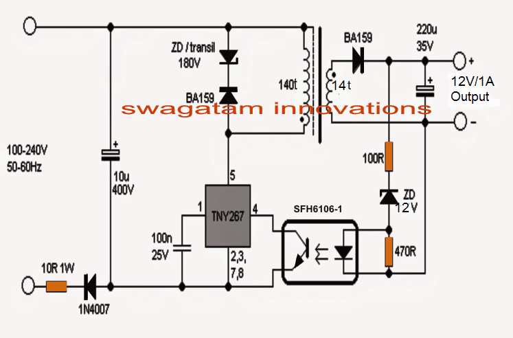
Martins, the wattage of the following mobile charger circuit will be 5 * 1 = 5 watts, if the zener diode is adjusted to 5V or 6V:
I have a problem. I an trying to build a cell phone charging battery bank for my wife. I will do a few things. I have used a few over the counter circuits to connect to get what I want. I can not get a cell phone charging circuit that will run on 4.5v. they all need 5v. its has 3 Ni-MH 1.2v Id I put 1 4th battery to get it to the 5v range the charging circuit stopped working.
Please measure the output voltage from the battery after connecting to the cellphone, it should be 5V or slightly above 5V. If not, then your cellphone will reject the charging and the charging supply will not be accepted.
I am very impressed with your work and will want to learn from you. I am new in it but passionate about electronic design. Thank you.
Sure, you can ask your questions here, and I will try to solve them asap…
Hello sir,
I was trying to construct a charging indicator circuit. I want the circuit to work like this: when a load (output) is connected, I want it to change the indicator from the initial colour (LED) to a different colour and vice versa.
Martins, which charging circuit are you using for interfacing the mentioned indicator? Please provide me the charger circuit then I will tell you how to integrate the LEDs in it…
Good day Sir.
I wish to find out if it’s okay to replace the pnp transistor on the last circuit of number. 4 with an npn?
Connecting the collector of the npn to R1, and the emitter to output of 7805
Thank you
Good Day Godwill,
No, it should be NPN only, configured as emitter follower, so that the average voltage at its base is exactly fed to the mobile charger battery also, which can happen only with this NPN configuration..