In this post I have explained the construction of a simple emergency charger pack using Nicket Cadmium (Ni-Cd) batteries for your cellphones and smart phones for emergency charging of your cellphone, so that next time you are never stuck on a highway with a full discharged dead cellphone battery.
Circuit Concept
It often happens, our cell phone goes into a low battery condition right in the middle of an important conversation, and even worse it happens while we are travelling or situated in some remote outdoor location where there's no charging facility available.
No matter what, this little pack will give your cell phone an immediate refill every time it tends to get flat outdoors.
We all know that at 3.7 V DC, a cell phone battery is considered to be fully charged.
For charging it at the above level a charging source needs to provide around 4 to 5 volts to the discharged cell phone battery.
Since here we are discussing an energy transfer from one battery to the other or rather from some power source to the cell phone, we need to have some sort of chargeable battery pack which would generate the required 4 volts and which could be used anytime for charging a flat cell phone simply by integrating the two together.
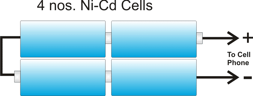
The above emergency battery pack can be very easily made by putting four Ni-Cd cells in series.
I have explained how to do it.
Materials you will Require
It's not difficult, you would require four 1.2V Ni-Cd AAA penlight cells, a four cell holder assembly and a 1 Ohm 1 watt resistor.
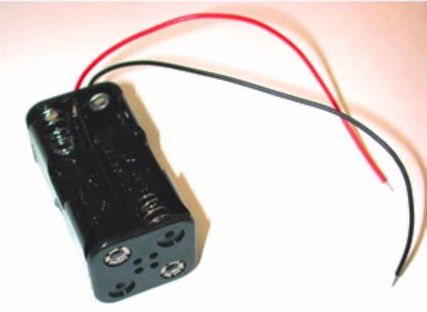
How to Build the Cellphone Battery Bank
The above holder would generate a voltage of about 4.8V at its wire terminals with four AAA 1.2 Ni-Cd attached to within the given slots correctly.
The 1 Ohm resistor can be connected at the center of the red wire by cutting the red wire at the center and bridging the resistor terminals such that it comes in series with the red wire. The resistor should covered under a plastic tubing or sleeving.
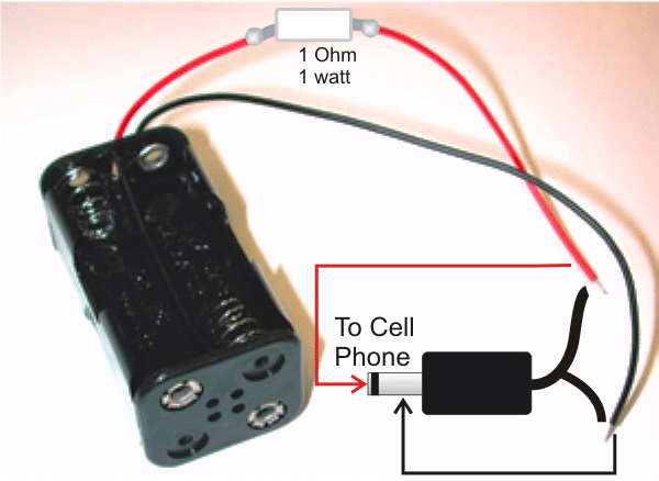
The red and the black wires of above assembly should be terminated with a suitable cell phone charger-pin so that it can be easily inserted into the cell phone charging socket whenever required.
Now I have explained how we can charge the above emergency battery pack at home.
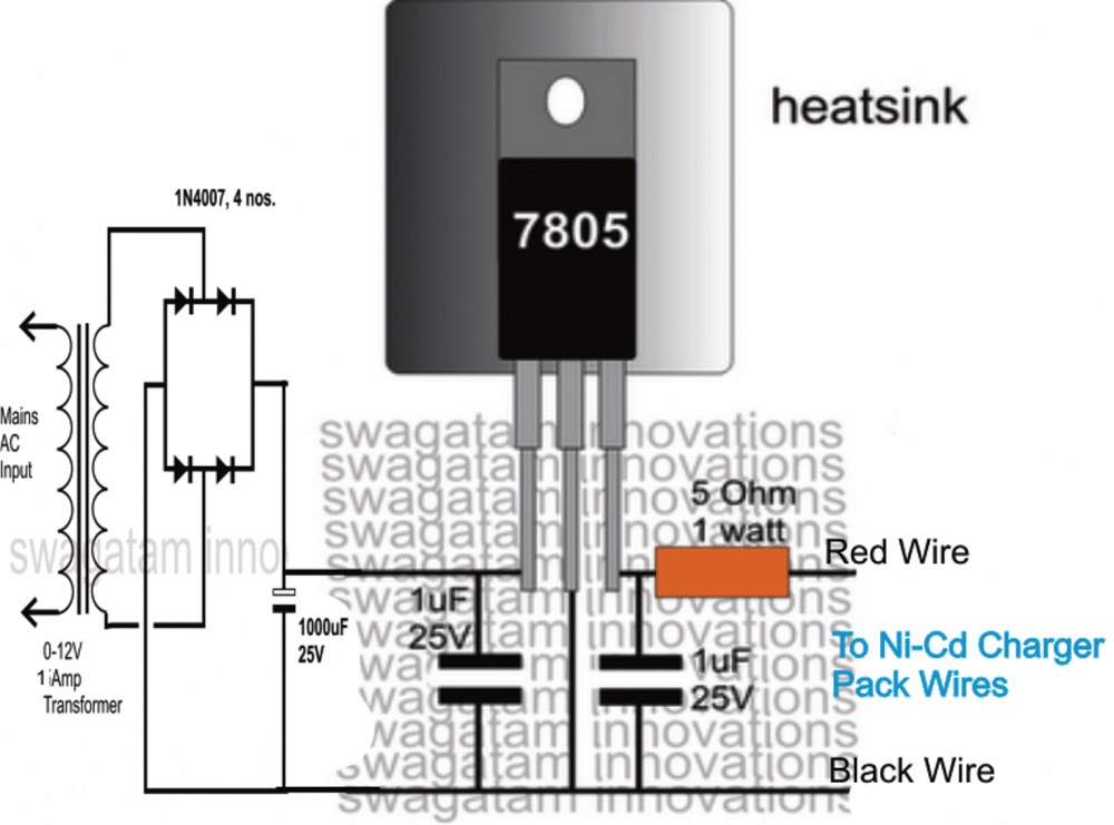
Ni-Cd cells can be charged safely for about 10 to 14 hours using a constant voltage charger at C/10 rate. The very useful 7805 voltage regulator IC can be used here for charging the Ni-Cd battery pack.
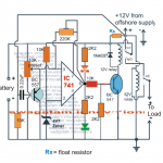
The following diagram shows a very simple Ni-Cd charger circuit which can be used for charging the above battery pack so that it remains in a standby position and can be taken outdoors in the form of an emergency cell phone charger unit.

Questions & Answers
I want to design a portable laptop power bank that can last for 24hours. how do I do please my engineer.?
Hi Aliyu, you can refer to the following post for more information:
https://www.homemade-circuits.com/laptop-power-bank-circuit/
For 24 hour backup you will have to upgrade the Ah rating of the charger battery accordingly.
Can you help me. I live where there is no electricity grid in Brazil. For almost 4 years with the limitation of electricity by not knowing the electronics. You are looking to learn and sell in alternative alternatives, but I have the financial limit.
Generally available from a stationary 12v / 12Ah battery and some 3.7v Lithium batteries. Fueled by a 12v / 20w solar plate, mini 12v hydroelectric generator and I’m trying to make a three-phase wind turbine and other small ones with printer motors.
All knowledge and help are welcome.
Do you have an email that I can share some of your knowledge and remove some doubts?
Tanks
Marcelo, I’ll try to help you, but I would prefer discussing it here through comments so that other readers are also able to benefit from our conversation.
Thank you for your attention and response.
I experimented with a modulus xl6009 DC-Current Continuous Boost Buck Adjustable Step Up and I was able to charge a cell phone and another li-ion battery.
I made the joule thief with a ceramic capacitor 103 and a 1k resistor at the input, a toroid (2×12 turns), TIP 31c, a diode 1N5148 and electrolytic 1000uF / 25v, but I can not even recharge another battery, even having 6v at the output .
Could you change this setting to try loading?
Can you please tell what supply input did you use for the mentioned module? The module has a specilaized IC so the output will be much efficient. 12 turns is quite less…try 20 turns at least and check the response…and use 7805 IC after the 1000uF for stabilization. In my case the battery wasn’t strong enough to sustain the smartphone charging current…if possible I’ll try to use a bigger battery as the input and check the response.
OK! No problem, just thought if there is need to send you some photo or circuit design. Can you do this around here?
I understand about xl6009. It adjusts output according to requirement. Right?
I used a 3.7v and 1200mAh Lithium cell phone battery, marking 4.2v.
My problem is to lose a little of the charge of the batteries they power.
Tanks
Good afternoon sir.
Thanks for the site and tips.
Could I use a single 1800mAh cell phone battery in a joule thief to power a cell phone via usb?
Because I have 6 v, but I can not even charge another battery of 3.7 v and 1000 mAh?
Please help me
Thanks Marcelo, Do you mean you want to charge your phone through a 1800mAh cell using joule thief and USB connector? It will depend on the phone actually, when I tried, my phone did not accept the charge due to voltage drop issue each time I tried to connect the cord. So it’s better to use two cells instead of one and use a 7805 for regulating the output to 5V, as shown here:
Sir can u give me a circuit which has output 1.5-2.0 amp and 5v to charge my 3000mah battery 2 times…please…
Thanks in advance…
Abhijit, you can make the following circuit….make sure to replace LM317 with LM338, otherwise you might not get above 1.5 amps
https://www.homemade-circuits.com/p/lm317-calculator.html
next, calculate the R1, R2 from the software to get 5V at the output and then you can use it for your purpose
Sir can you give me a circuit according to my requirements … Please…..Sir..
Abhijit, make a LM338 circuit and supply 12V/2amps, adjust the circuit at 5V and then you can use it for your smart phone.
Sir what is the output ampere and voltage of this…
without resistor it's around 1 amp
voltage is 5V, and the ampere depends on the value of the resistor.
Sir can I use this circuit for charging my 3000mah battery
Thanks in advance….
Abhijit, you can use the 7805 circuit for charging your 3AH battery but it will be quite slow…
Hi Swagatam,
Can I use nokia BL5C battery
(3.7v-1020mAH) as power bank to charge a smart phone?
you will need two of those in series, and a calculated resistor in series at the positive while charging the smart phone
Dear Sir
I need 4200ma polymer battery charger circuit after 3 min minimum 20% quick charge
I am try many circuit but all of circuit component very hot and burn sum time.
I try 5V out put and 3A Charge circuit this 3 min charge OK but all component vary hot .i thing this circuit not a nap pl z.. help me
My Email ID-giashsmart@gmail.com
Dear Giash, Lipo batteries normally require a balanced type ofcharger, what is your exact requirement? please specify.
hi SWAGATAM , how can i modify that circuit to charge a 9.6V Ni-cd battery pack
Hi Davis, you can do it by replacing the 7805 IC with a 7812 IC
Sir I have 2 18650 2200mah cells I want to charge my android requiring. 5v@1amp how should I proceed any simple circuit with only 2-3 components
you will require a 5V/2amp adapter for this, without an adapter charging cannot be done.
Hello sir
I have 3. 7 v battery i want to make a power bank can you please tell me how do i make it i also want a circuit diagram
Thanks
Sir,can i use this charging circuit for charging Alkaline Batteries?
Mehran, you can use it for charging all types of batteries, just make sure to switch OFF power as soon as the full charge level is reached.
hello Sir,
i want to known that can i charge a single nicd 1.2volt cell from 5v mobile charger.
hello Muhasin, you can do it by employing the following circuit and the mentioned modifications:
https://www.homemade-circuits.com/2012/08/simplest-dc-cell-phone-charger-circuit.html
replace the output with your battery terminals, input supply from charger, replace 9V zener with 3 1N4007 diodes in series ….but cathodes pointing towards the ground line.
and make the 220 resistor into 1K
Thanx sir
Hello sir the last circuit indicate as the charger…………….. bt how to know that cells are fully charged any indication for that we can add to the circuit
Hello Basit, you can add an LED with 1K resistor in parallel with the 5 ohm resistor…it'll stay illuminated as long as the battery is charging and will slowly shut off as it gets fully charged
Please tell me about 4V Dc To 5V converter.
Thanku sir once again. I wank to ask one question sir,that is can i make solar inverter with very low budjet like 500 or 600
Karthick, It is possible without solar panel and battery, you can buy a cheap Chinese inverter and check how it was possible for them to make so cheaply.
Thanku sir, can i use the breadboard for the charging circuit?
you can try it.
Thank u sir. I bought this ckt sir it is working good.but my question is how many hours i hav to charge those cells if the cells discharged
You can keep it connected for 5 to 6 hours for making the cells fully charged.
Thank u for ur reply sir.how can i charge those cells using ac power in my home .
The circuit has been provided at the end of the above article, please check it.
hai sir can i make a simple inverter circuit for my home with in 500 rupees
at Rs.500/- it's not possible to build a reasonably sized inverter circuit
hai sir i am often visiting your site it is really wonderful .i just want to ask a one doubt in this emergency circuit package which is"is the ni-cd can be rechargable or not".please reply me soon sir.
Hi Karthick, thanks for visiting my blog!
yes, Ni-Cd cells are always rechargeable types, and needs to be charged when fully discharged
hello this one is good
Hi uel,
you can make a dual adjustable power supply circuit using a LM317/LM337 ICs, Google it, you will find plenty.
set the voltages as per your requirement and use it for the application.