A DC cell phone or mobile phone charger is a device which charges a cellphone from an available DC supply source. The device converts the unregulated DC source into a constant current and constant voltage output which becomes safe for any mobile phone charging.
In this article I have explained how to build DC to DC cell phone charger circuits using 6 unique concepts. The first concept concept uses the IC 7805, the second concept works with a single BJT, the third idea uses a IC M2575, in the fourth method we try LM338 IC, the 5th circuit shows how to charge multiple mobiles from a single source while the last or the 6th technique shows us how to use PWM for implementing an effective charging of a mobile phone.
Warning: Although the concepts are all tested and technically correct, the author does not take any responsibility of the results, please do it at your own risk.
Introduction
A simple DC cell phone charger circuit is one of those mates of cell phone that cannot be ignored because a cell phone would be dead without a charger.
Normally a DC cell phone charger circuit come as an integral part of a cell phone package and we use it in conjunction with our AC mains supply.
But what happens if your cell phone gasps for power in the middle of a journey, probably when you are driving or biking away on a middle of a highway?
How it Functions
A very simple yet reasonably effective DC to DC cell phone charger circuit is discussed in this article, which can be easily built at home even by a layman.
Though the proposed charger circuit won't charge your cell phone at the rate equal to a normal AC to DC charger, nevertheless it will complete the function without fail and won't betray you for sure.
The proposed DC cellphone charger circuit can be understood with the following points:
We all know the general specs of a cell phone battery, it's around 3.7 volts and 800 mAH.
It means the cell phone would require at around 4.5 volts for initiating the charging process.
However a Li-Ion battery which is employed inside cell phones are pretty sensitive to bad voltages and may just blow off causing serious life and property issues.
Keeping this in mind the cell phone internal circuitry is specifically dimensioned very strictly.
The parameters just won't permit any voltage which may be even slightly out of the range of the battery specifications.
The use of the versatile IC 7805 in the circuit answers the above issue just perfectly, such that the charging voltage at its output becomes ideally suitable for charging the cell phone battery.
A high wattage resistor connected at the output of the IC makes sure that the current to the cell phone stays well within the specified range, though this might have not been a problem anyway, the cell phone would just refuse to charge if the resistor was not included.
1) Circuit Diagram of the DC cellphone charger
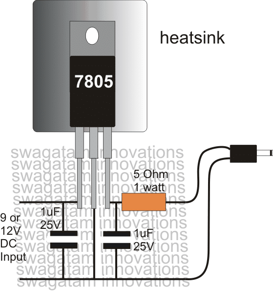
Pictorial Diagram
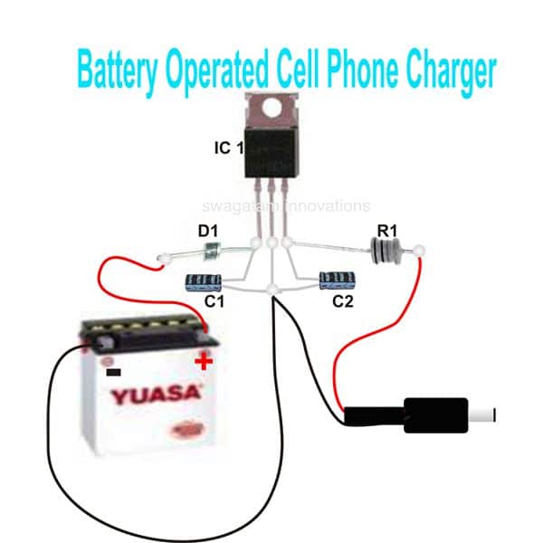
You can use this DC cellphone charger circuit for charging you cell phone during emergencies when there's no mains AC outlets, the circuit may be powered from any 12 volt lead acid battery or similar DC power source
Parts List
R1 = 5 Ohm, 2 Watt,
C1, C2 = 10uF/ 25V,
D1 = 1N4007,
IC1 = 7805, mounted on a heatsink,
Battery, any 12 volt automobile battery
Using LM123/LM323
In the above concept a 7805 IC is used for charging, which can deliver a maximum of 1 amp. This current may not sufficient enough for charging smart phones, or cellphones with bigger mAH rating in the range of 4000 mAh. Since these high current batteries may require current up to 3 amps for charging at reasonably fast rate.
A 7805 might be completely useless for such applications.
However, the IC LM123 is one candidate which can fulfill the above requirement, by providing a precision 5 V output with a good 3 amp current. The input can be from any 12 V source such a car/motorcycle battery, or a solar panel. The simple 3 amp mobile phone charger diagram can be seen below:
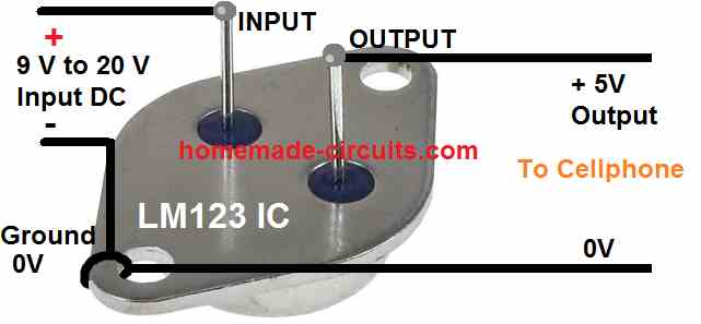
As can be seen above the 3 amp charger circuit requires no external components for implementing the procedures, and yet is extremely precise with its output voltage and current regulation, and is virtually nondestructive due to it many internal protection features.
2) DC Cell phone Charger using a Single Transistor
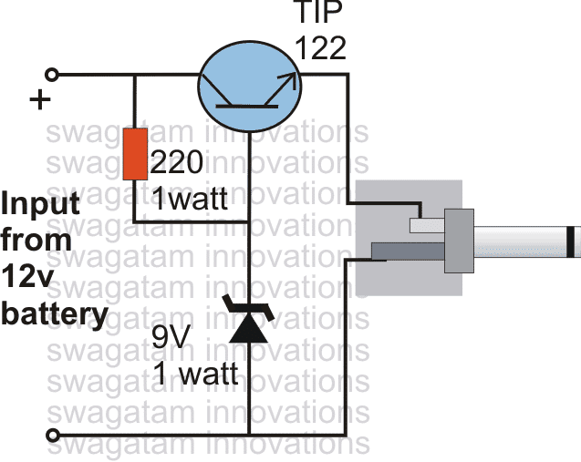
The next design explains a DC cell phone charger using a single BJT is probably the simplest in its forms and may be built very cheaply and used for charging any standard cell phone from a DC 12 volts external source.
Circuit Operation
The circuit diagram illustrates a rather straightforward design incorporating very few components for implementing the proposed cell phone charging actions.
Here the main active part is an ordinary power transistor which has been configured with another active part, the zenet diode for forming a nice little DC to DC cell phone charger circuit.
The resistor is the only passive component other than the above couple of active parts which has been associated in the circuit.
So just three component is to be used and a full fledged cell phone charger circuit is ready within minutes.
The resistor acts as the biasing component for the transistor and also acts as the "starter" for the transistor.
The zener has been included to inhibit the transistor from conducting more than the specified voltage determined by the zener voltage.
Though, a cell phone ideally requires just 4 volts for initiating the charging process, here the zener voltage and subsequently the output voltage has been fixed at 9V, because the current releasing ability of this circuit is not very efficient and presumably the power should be dropping to the required 4v level once the cell phone is connected at the output.
However the current may be decreased or increased by suitably increasing or decreasing the value of the resistor respectively.
If the cell phone "refuses" to get charged, the resistor value nay be increased a bit or a different higher value may be tried for making the cell phone respond positively.
Kindly note that the circuit was designed by me based on assumptions only and the circuit has not been tested or confirmed practically.
Circuit Diagram
3) Using 1-A Simple Step-Down Switching Voltage Regulator
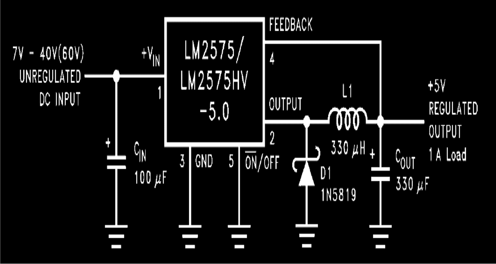
If you are not satisfied with a linear regulator charger, then you can opt for this 1 A simple step-down switching voltage regulator based DC cell phone charger circuit which works with a switched buck converter principle which enables circuit to charge a cell phone with great efficiency.
How it Works
In one of my previous posts I have explained about the versatile voltage regulator IC LM2575 from TEXAS INSTRUMENTS.
As can be seen, the diagram hardly utilizes any external components for making the circuit functional.
A couple of capacitors a schottky diode and an inductor of all that is needed to make this DC to DC cell phone charger circuit.
The output generates an accurate 5 volts which becomes very much suitable for charging a cell phone.
The input voltage has a wide range, right from 7V to 60V, any level ma be applied which results the required 5 volts at the output.
The inductor is introduced specifically for obtaining a pulsed output at around 52 kHz.
Half of the energy from the inductor is used back for charging the cell phone ensuring that the IC remains switched only for half the charging cycle period.
This keeps the IC cool and keeps it effectively in working even without using a heatsink.
This ensures power saving as well as efficient functioning of the entire unit for the intended application.
The input may be derived from any DC source like an automobile battery.
Courtesy and Original Circuit: ti.com/lit/ds/symlink/lm2575.pdf
4) DC Double Cellphone Charger
A recent request from one of my followers Mr. Raja Gilse (via email), prompted me to design a DC double cellphone charger circuit that is able to facilitate charging of many cell phones simultaneously, I have explained how to make the circuit.
I have already explained regarding a couple of DC to DC cellphone charging circuits, however all these are designed for charging a single cell phone. For charging more than one cell phone from an external DC source like an automobile battery, requires an elaborate circuit.
Technical Specifications
Dear sir. Please tell me that what alterations should i do, to charge two mobiles at a time from your "12V BATTERY OPERATED CELL PHONE CHARGER CIRCUIT".(from bright hub) I am using the circuit from last 8 months, it's fine. Please post that article in your new blog also.
Dear sir, i tried so many time to post this comment in your blog in the "simple dc to dc cell phone charger circuit" but in vain. Please answer here~ Sir, i used another 10 ohm 2 watt resistor in parallel with the existing one, as i don’t have the higher watt resistor. It’s working fine. Thank you very much, i have one doubt, earlier, in bright hub in the same article you told to use 10 ohm resistor, but here it is 5 ohm which is suitable ?
I have another question out of this article; please guide me could I use three 1N4007 silicon diode instead of one 1N5408 silicon diode? My aim is to allow 3A current in only one direction. But i don’t have diode of 3A i.e. 1N5408. As 1N4007 is of 1 amps capacity could use three 1N4007 in parallel and like wise for 5A five 1N4007 in parallel, because i have number of 1N4007
rajagilse
Solving the Circuit Request
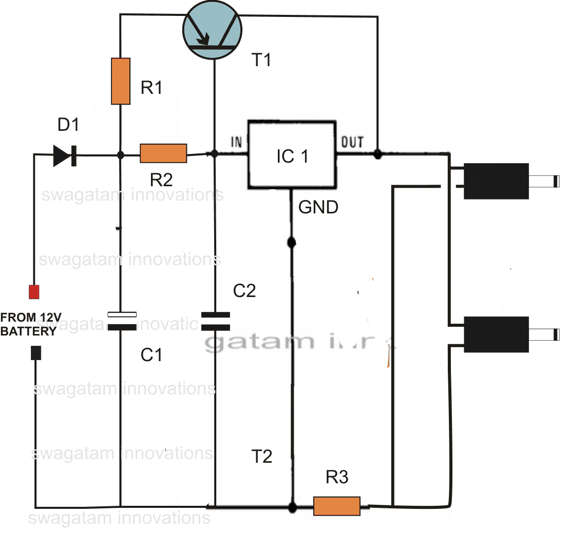
Hi Rajagilse,Use the following DC double cellphone charger circuit given below:
Hi Raja,
As you increase the limiting resistor value, the charging becomes slower, therefore a 5 Ohm resistor would charge the cell phone faster than a 10 Ohm, and so on. I'll check the problem with the commenting in my blog...however other comments are coming normally as usual! Let's see. Thanks and Regards.
Parts List
- R1 = 0.1 Ohms 2 watt,
- R2 = 2 Ohms 2 Watt
- R3 = 3 Ohms 1 watt
- C1 = 100uF/25V
- C2 = 0.1 discT1 = BD140 D1 = 1N5408
- IC1 = 7805
PCB Design
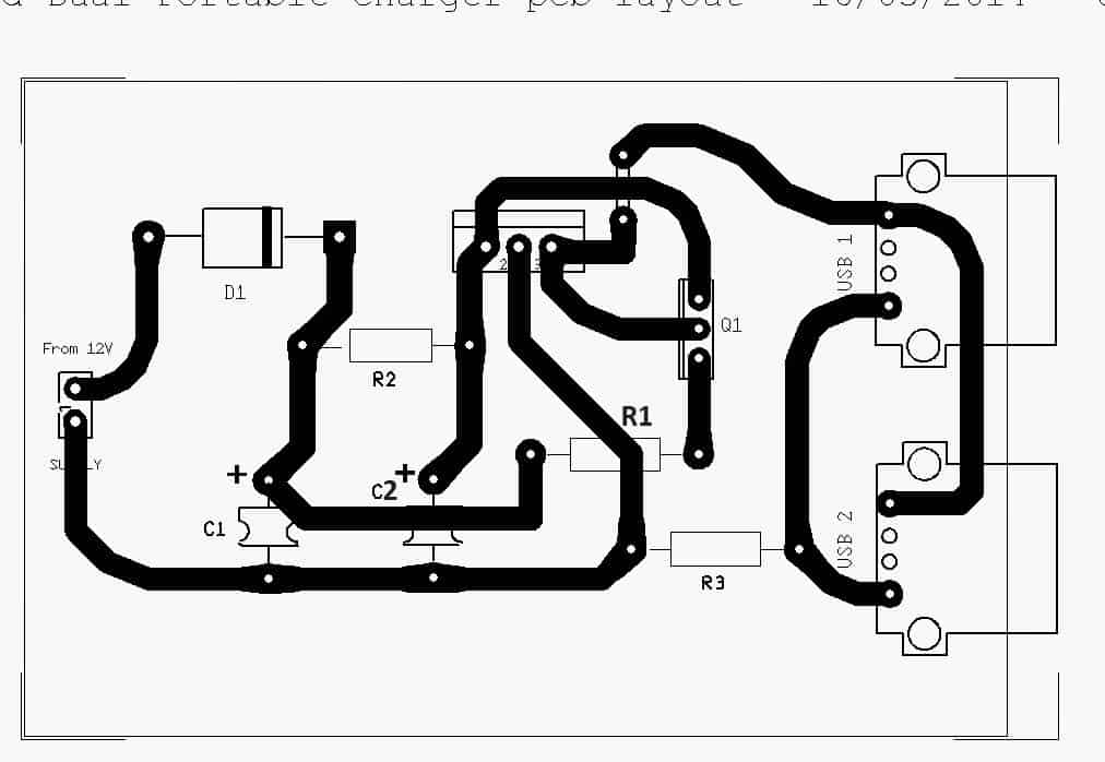
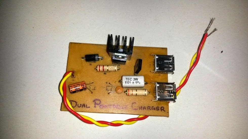
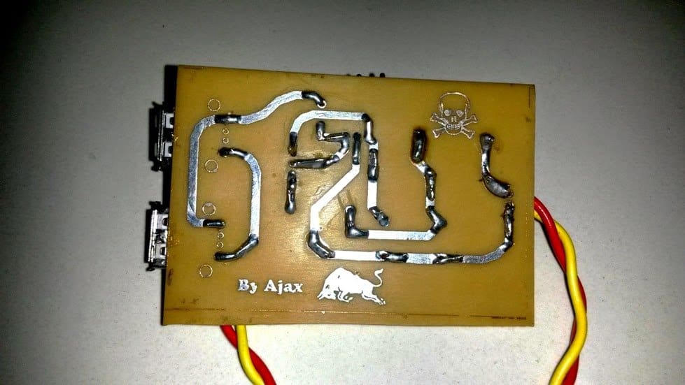
The circuit of the double DC cell phone charger was successfully tried and built by Mr. Ajay Dussa over a home designed PCB, the following images of the PCB layout and the prototype were sent by Mr. Ajay.
5) LM338 Based Cell Phone Charger Circuit
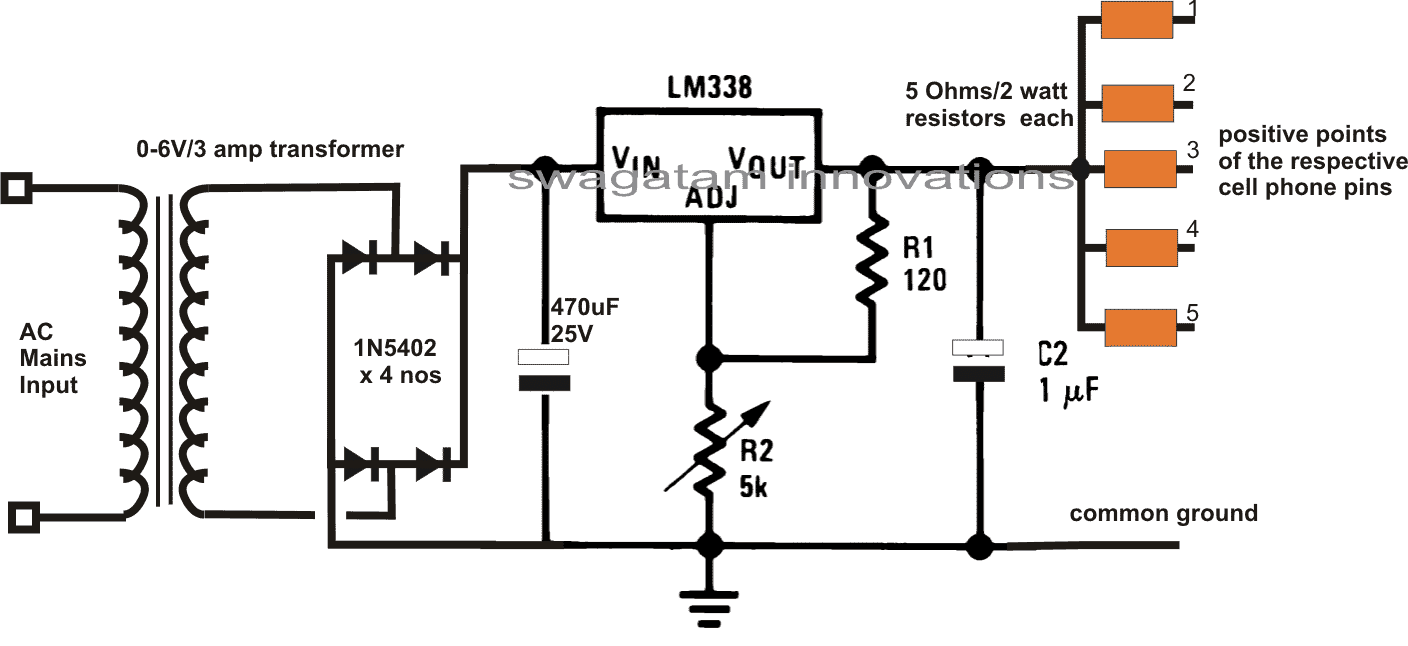
The following circuit can be used for charging as many as 5 cell phones at a time. The circuit employs the versatile IC LM338 for producing the required power. The input is selected to be a 6V but can be as high as 24V. A single cell phone can also be charged from this circuit.
The circuit was requested by Mr. Ram.
Multiple Cellphone Charger Circuit using IC 7805
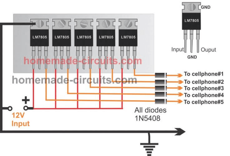
Any desired number of cellphones can be charged by using IC 7805 in parallel as shown the following figure. Since the ICs are all mounted on the same heatsink the heat among them is uniformly shared ensuring a uniform charging across all the connected multiple cellphone devices.
Here 5 ICs are used for charging by medium sized cellphones, more number of ICs could added to accommodate more number of cellphones in the charging array.
6) Using PWM For Charging Cellphone Battery
This circuit can be easily made at home by any school kid and used for displaying in his science fair exhibition. The circuit is a simple cell phone charger that may be operated in conjunction with any DC source, from a car or a motorcycle battery or from any ordinary 12 V AC DC adapter.
Nowadays we find most of the vehicles have their in built cell phone battery charger units which surely becomes very handy for travelers who mostly remain outdoors travelling in their vehicle.
The proposed cell phone charger circuit is as good as the conventional chargers which come fitted inside the cars and bikes.
Moreover the circuit can be simply integrated to ones own vehicle if the feature is not originally available in the vehicle.
Alternatively one may think of manufacturing the present unit and selling them in the market as an automobile cell phone charger and earn some hard bucks.
Circuit Operation
Cell phones as we all know are highly sophisticated gadgets by nature and when it comes to charging cell phones the parameters no doubt also needs to be of very high standards.
The AC/DC cell phone chargers which come with the cell phones are all SMPS based and are extremely good with their outputs and that’s why the cell phone gets so efficiently charged by them.
However if we try to make our own version, it may fail altogether and the cell phones may just not respond to the current and display a “not charging” on the screen.
Cell phone battery cannot just be charged by supplying DC 4 volts, unless the current is optimally dimensioned the charging won’t initiate.
PWM vs Linear
Using voltage regulator IC for making a DC to DC charger, which I have discussed in one of my earlier article is a good approach, but the IC tends to become too hot while charging the cell phone battery and therefore requires adequate heatsinking for remaining cool and operative.
This makes the unit a bit bulkier and moreover some significant amount of power is wasted in the form of heat, so the design cannot be considered very efficient.
The present PWM controlled DC to DC cell phone charger circuit is outstanding in its respect because, the involvement of PWM pulses helps to keep the output very suitable to the cell phone circuitry and also the concept involves no heating of the output device, making the entire circuit truly efficient.
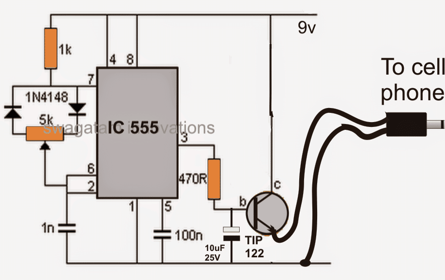
Looking at the circuit we find that again the work horse IC 555 comes to our rescue and performs the important function of generating the required PWM pulses.
The input to the circuit is supplied through some standard DC source, ideally from an automobile battery.
The voltage powers the IC which instantly starts generating the PWM pulses and feeds it to the components connected at its output pin #3.
At the output the power transistor is used for switching the DC voltage at its collector directly to the cell phone.
However only the average DC voltage is finally fed to the cell phone due to the presence of the 10uF capacitor, which effectively filters the pulsating current and provides a stable, standard 4 volts to the cell phone.
After the circuit is built, the given pot will need to be optimized perfectly so that a well dimensioned voltage is produced at the output which may be ideally suited for charging the cell phone.
Circuit Diagram


Questions & Answers
diode is placed only for safeguarding the circuit from accidental reverse input connection. You can remove it but be sure you connect the input polarity correctly then.
thanks sir
sir can you tell me how much time required for charging a mobile???
& sir i have project about bicycle dynamo. sir if you don't mind can you send me an easy diagram to make bicycle dynamo/bicycle generator??
2 to 3 hours will be required.
you can connect the dynamo output to the above circuit via a bridge rectifier stage and start charging the cell phone as explained above.
it help me alot.THANKS SIR…
sir app bta skte ha k ak battery ktne dair run kr skti haa??
i mentioned it in the previous comment, 2 to 3 hours.
sir can i connect this circuit with motorbike battery and car battery??
if yes ,so will there any problem of input & outout current because automobile battery's current is very high??
i know voltage is not a problem.. what about current.
THANKS FOR YOUR ALL PREVIOUS HELP SIR…..
As long as the input voltage is within 24V, current will not mater, so you can use it freely with your motorcycle battery also.
THANKS SIRRR
THANK YOU…!!!
sir please tell me if you have any knowledge about any softwere about circuit designing in which bicycle dynamo ,d.c motor or other mechanical equipments present????
No, sorry I don't have any such software.
you can use the same circuit which is shown above.
Hello Omar, just replace the 7805 with a LM123 and it will become suitable for the required application.
sir,this condition ok…the 12v continuously going at 7805 and step down to 3v…normally example you take mobile charger,u have charging mobile, charging and the battery is full….and automatically disconnect the charger….
in this project,only charging the battery not getting the charge is full condition automatically disconnect condition..how to get automatically disconnect after the batter full..plz give me the circuit and information………
Dear Sir ,
I would to know , can I use this circuit to power up mobile phone without battery attached.
Thanks in advance.
Nope! the circuit will require an input source, otherwise it won't work
Dear Sir ,
Can i use your diagram to power up my cell phone without attached the battery to the phone?
Thanks
mobile chargers do not have auto shut off feature, rather cell phones have auto cut off feature in-built, therefore it's safe because the cell phone in-built circuit would cut off as soon as its battery gets fully charged.
If it's 4V then it would charge your cell phone when hooked directly, anything less than 4V would make the charging inefficient and sluggish.
You are welcome!
No changes would be required, use the same circuit for 6V input.
yes you can.
can i use mobile charger to start motor?
motor = 0/6.0 v
charger = output – DC 6.0 v
can i use mobile charger to start motor?
motor = 0/6.0 v
charger = output – DC 6.0 v
yes you can
HELLO SIR..
SIR MJHE UNI PROJECT K LIA AK CIRCUIT CHAHEA JISME 2 IC lm714 US HO..SIR PLEASE KOE HOMEMADE PJOJECT KA LINK SEND KR DIJEA..
I WILL BE THANKFUL TO YOUU…………….
Hello Abdul,
You can try the first circuit given in this link:
https://www.homemade-circuits.com/2011/12/how-to-build-electronic-spy-bug-circuit.html
….sorry, the above circuit uses a single 741, try the following one, replace the LM324 opamps with two IC741:
https://www.homemade-circuits.com/2012/04/make-this-simple-motion-detectorsensor.html
thanks sir.
but I m student of 3rd semester. this schemetic is little bit complex
for me.so sir please send me an easy schematic. so I can make it .
thank u sir for helping me a lot… …
Hi Abdul,
I don't have any simpler circuit than this at the moment, I'll try to find it and tell you soon.
HELLO SIR……..
SIR APNE JO SEND KIA THA LINK ME WOHE BNA RHA HUU..
MENE APKE BLOGES ME RELAY CONNECTION PARHA . KCH SMJH AYA SIRF YH BTA DE AP K JO RELAY KI 5 PINS HA WO KHA KHA CONNECT HA???
N/C & N/O KHA CONNECTED HA:COIL TERMNALS KHA CONNECTED HA??
AUR JO PICTURE ME 12 VOLT K UPAR BLUE LINE HA WO KHA CONNECT HORAE HA.
SIR I HAVE ONLY 3 DAYS TO MAKE IT .
THANKSS…..
The square box named 'relay" is the coil of the relay, among the contacts the upper circle is the N/C and the lower circle is the N/O, the central link is the moving pole of the relay.
THANKS SIR.. YOU CLEARED MY CONCEPTS.
BS MJHE YH BTADE N N/O, N/C & MOVING POLE OF THE RELEY CIRCUIT ME KHA CONNECTED HAIN????AK TO YH RELAY ME CONNECTED HA LEKIN YH CIRCUIT ME KHA CONNECTED HA YH NAE PTA CHAL RAHA..
N/O, N/C and the pole are not connected to the circuit, they are connected to the load or an alarm via AC mains, there's no connection with the circuit.
If you are using a DC alarm then you may connect it with the circuit 12v supply.
ok sirr
sir jo 12 volt dc alarm ha iska koe link send krde. mjhe zehan me idea nae arha..
project bhht acha lga ha mjhe iSlia yhe bnana cha hu.complex ha but i will try my level best.
aur relay ki 3 wire jo alarm se connect HA uska be lnk btade
THANKS SIR…….
sir mjhe dc alarm ka idea nae ho rha. plz send me link about dc alarm. aur is circuit me sensor knsi chez ha jaha se motion indicat hogi aur alarm on hoga
don't make the aarm, buy it from the market, you can use a car musical horn or a 12v musical door bell.
relay connection:
pole to 12V(+), N/O to alarm (+) wire and (-) of alarm to circuit ground or supply negative.
THANKS SIR..
sir yh jo diagram me A1 HA ISKI Pin 1 to led k sth aur pin aur pin 2 potentiometer k sth ha but confusing pont is k pin 1 & pin 2 k bech me se ak point upar 12 volt aur resister k sth node bna rha ha. yh ks pin se nkal k upar ja rha ha.aur sirf A1 KI 3 PIN CONNECTED ha bki kia ground krni ha???
and same question for A2 .usme be pin 5 & 7 connected ha aur bech mese ak wire jake grounded ha.yh knsi wire ha???
SIR IS THERE ANY WAY TO CONNECT WITH YOU & YOUR KNOWLEDGE DIRECTLY????
BECAUSE SOMETIMES I WANT QUICK ANSWERS AND FROM BLOGS, I HAVE TO WAIT 1 DAY. KINDLY TELL ME ANOTHER WAY SO THAT I CONNECT WITH YOU DIRECTLY ..
THAKNS SIR..
It's the supply pins of IC324….positive line goes to pin4 and the ground pin goes to pin11.
I am sorry you can contact only through this blog.
SIR………
datasheetoo.com/datasheet-application/automotive/electronic-siren-circuit-diagram-using-741-op-amp-ic.html
THIS IS ELECTRONIC SIREN . SIR I WANT TO ASK THAT SPEAKER IS PRESENT THERE,WHERE I CONNECTED INPUT SOUND SO SPEAKER CAN AMPLIFY???
THANKSS SIR FOR HELPING ME A LOT…
I did not understand your question, what are you trying to make?
Sir please tell me connection of relay with dc alarm . I am using dc alarm for output.
Secondly, if I want to check the circuit that it is working or not without an alarm, how I check it???
Actually mjhe teacher ko check krwana ha without alarm.
relay connection:
pole to 12V(+), N/O to alarm (+) wire and (-) of alarm to circuit ground or supply negative.
The red leds will be shut off after setting up, and when a motion is detected across any of the LDRs the relevant red LED will light up indicating a motion.
This means sir that N/0 does not use in this circuit.??
And pole se phir 12 volt p connect krna ha?? I can't understand. Please send any diagram from which I understand.
THANKS….
pls read the connections again, N/O is connected to (+) of alarm circuit, N/C is blank, not connected anywhere.
(-) of alarm circuit is connected to supply negative
relay pole is connected to supply positive
I UNDERSTAN SIR..
SIR IN MY CIRCUIT,ONLY ONE LDR IS WORKING ,WHEN I DISCONNECT ONE LDR,OTHER LDR WORK AND OTHER PROBLEN IS THAT IT WORKS IN OPPOSITE FORM MEANS WHEN IT DETECTS ANY MOTION,LED OFF OTHERWISW IT ON ALL THE TIME.
AND SIR TELL ME HOW I SET P1 & P2???
THANKSS….
will depend on the AH rating of the battery and the phone.
Ravinder Kumar from Indigenous Home made Tech is here -Dear sir i used u r given circuit (with C1,C2= 10uF/25V )BUT by using diode and resistance does not work ,so i have removed diode and resistance now its charge but not 100% it charges the cell phone only to 70% by using 6volt 4.5Ah Battery ,
Request you please suggest to increase charging efficiency limit to 100% .
I am sorry the above circuit cannot be upgraded any further. You can use an LM338 design and adjust the voltage to suit the cell phone needs. You may refer to the first circuit in this link:
https://www.homemade-circuits.com/2012/04/ic-lm338-application-circuits-explained.html
hello sir!!!!
can u please tell me what is the function of capacitors in the above circuit ???
Hello Danish,
It's there for filtering noise and voltage spikes.