In this article I have explained how to build a digital voltmeter and a digital ammeter combined circuit module for measuring DC volts and current through different ranges, digitally.
Introduction
Electrical parameters like voltage and current are inherently associated with electronics and with electronic engineers.
Any electronic circuit would be just incomplete without appropriate supply of voltage and current levels.
Our mains AC supply an alternating voltage at the potentials of 220 V, for implementing these voltages in electronic circuits we incorporate DC power adapters which effectively step down the mains AC voltages.
However, most power supplies don't include power monitoring systems in them, meaning the units don't incorporate voltage or current meters for displaying the relevant magnitudes.
Mostly the commercial power supplies use simple ways to display the voltages like a calibrated dial or ordinary moving coil type meters. These may be OK as long as the involved electronic operations are not critical, but for complex and sensitive electronic operations and troubleshooting, a hi-end monitoring system becomes imperative.
A digital volt meter and an ammeter become very handy for monitoring voltages and current perfectly without compromising safety parameters.
An interesting and accurate digital voltmeter and ammeter circuit has been explained in the present article which can be easily built at home, however the unit will require a well designed PCB for the sake of accuracy and perfection.
Circuit Operation
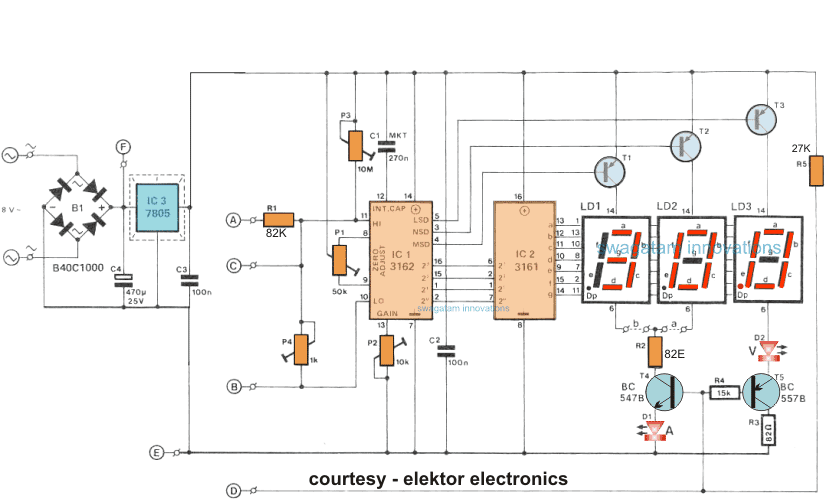
The circuit employs IC 3161 and 3162 for the required processing of the input voltage and current levels.
The processed info can be directly read over three 7-segment common anode display modules.
The circuit requires a 5 volt well regulated power supply section for operating the circuit and should be included without fail as the IC strictly requires a 5 volt supply for operating correctly.
The displays are powered by individual transistors which make sure that the displays are lit brightly.
The transistors are BC640, however you may try other transistors like 8550 or 187 etc.
The proposed digital voltmeter, ammeter circuit module can be effectively used with a power supply for indicating the voltage and current consumption by the connected load through the attached modules.
Referring to the circuit diagram below, the 3 digit digital display module is build through the ICs CA 3162 which is an analogue to digital converter IC, and the complementary CA 3161 IC which is BCD to 7 segment decoder IC, both these ICs are manufactured by RCA.
How the Displays Work
The 7-segment displays used are common anode type and are connected across the shown T1 to T3 transistor drivers for indicating the relevant readings.
The circuit includes the facility for the decimal point selection as per the load specs and range.
For example in the voltage readouts, when the decimal point illuminates at LD3 signifies a 100mV range.
For the current measurement the selection facility enables you to choose from a couple ranges, that is through a 0 to 9.99, and the other from 0 to 0.999 amps (using the link b). Which implies that the current sensing resistor is either a 0.1 ohm, or a 1 ohm resistor, as shown in the diagram below:
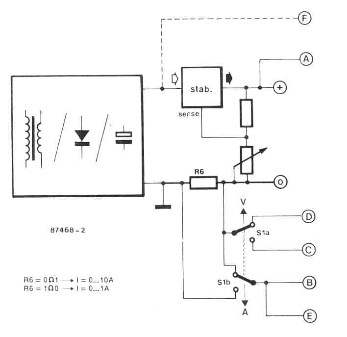
In order to ensure that R6 has no effect on the output voltage this resistor needs to be positioned prior to the voltage divider network which becomes responsible for controlling the output voltage.
S1 which is a DPDT switch is used for selecting either the voltage or the current reading as per the users preference.
With this switch set for measuring voltage P4 along with R1 provides an attenuation of around 100 for the fed input voltage.
Additionally the point D is enabled at a lower voltage level for allowing the illumination of the decimal point on the LS module, and the figure "V" become brightly illuminated.
With the selection switch held towards the Amp range, the voltage drop acquired across the sensing resistor is applied straight over to the points of the Hi-Low inputs of IC1 which is the DAC module.
The significantly low value of the sensing resistors ensures a negligible effect on the voltage divider outcome.
Adjustment Ranges for the Displays
You will find 4 adjustment ranges supplied in the proposed digital voltmeter ammeter circuit module.
P1: for nulling the current range.
P2: For enabling full scale calibration of the current range.
P3: for nulling the voltage range.
P4: For enabling full scale calibration of the voltage range.
It is recommended that the presets are adjusted in the above order only wherein P1, and P3 appropriately used for correctly nullifying the respective parameters of the module.
P1 helps to compensate the regulator operating quiescent current consumption value, which results in a minor negative deviation across their voltage range, which is in turn effectively compensated by P3.
The voltage/current display module works using the unregulated supply from the supply source without any issues (not to exceed 35V max), note the point E and F in the second figure above. In that case the bridge rectifier B1 can be eliminated.
The system might be designed like a twofold to acquire concurrent V and I readings. It ought to be recognized, however, that the current sensing resistor is short-circuited by means of the ground links each time the two devices are provided from the identical source. There are basically two methods to defeat this disorder.
The first is to hook up the V module from a different source, while the l module from the "host" supply. The second is a lot more graceful and necessitates hard wiring areas E to the left side of the current sensing resistor.
Be aware, although, that the highest possible V reading in that case turns into 20.0 V (R6 declines l V max.), because the voltage at pin ll usually will not surpass l.2 V.
Bigger voltages tend to be showed by choosing the lower current quality, ` i.e., R6 gets to be 0R1. Instance: R6 falls 0.5V at a current usage of 5 A, to ensure 1.2 - 0.5 = 0.7V continues to be for the voltage reading, whose optimum display is in that case 100 x 0.7: 70 V Just as before, these kinds of complications simply develop whenever a couple of of these units are employed all in one supply.
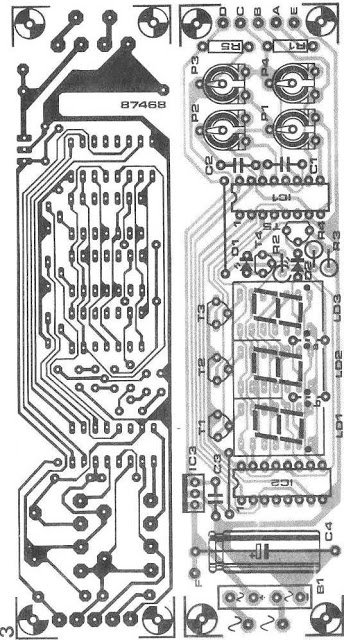
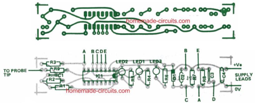
PCB design for making the above discussed modules

Questions & Answers
Hello Swagatam,
In the 90’s, I built a power supply (which burned out shortly after, as a result of some initial design errors) whose electronic schematic was taken from a website, which still exists today and whose schematic is still being commented and changed.
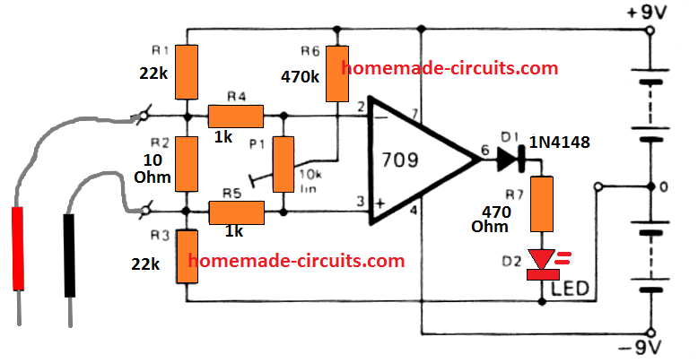
The respective volts/ammeters used were also built with the same ICs. However, they were carried out on the basis of a much simpler schematic. Only 3 trimers, 3 transistors, 2 capacitors, 3 precision resistors and 3 common cathode 7-segment displays are part of the entire circuit. But despite their simplicity, they had two advantages: The same scheme allowed to read voltage and current (so I made 2 separate circuits), and the decimal point was autorange according to the measured values.
A disadvantage that I remember at the moment, even having built two separate power supplies just for the reading modules, they were no longer accurate when the voltmeter and ammeter worked together, as mentioned in the article.
This schematic, I lost it, the only thing left are the PCBs built, if you are interested in the electronic schematic (despite these operating problems), the only way is to draw it by hand, what program do you use to draw the electronic schematics, built from scratch by you and posted here?
Best wishes,
Thank you Joao,
That sounds interesting! I normally use CorelDraw software to draw my schematics. For smaller designs I also manage drawing them using Microsoft Paint.
Hello dear Swagatam
I face a problem with my Regal analog multimeter and need your help Sir. It uses one 1.5V and one 9V battery that are both new. I set the range selector to R x1 ohm, connect the two probes to each other, and rotate the zero adjuster knob to right but the needle/pointer never reaches to zero ohm and stops on 2 ohms or more. Knowing that the needle is always set on zero by adjustment screw, what could be the reason?
Thank you so much in advance
Truly
Ersa
Hello Ersa,
I think the zero adjustment mechanism of the meter has become faulty. You can open the meter and check the zero mechanism, and then set it up manually.
Sir how to make a digital ammeter with HT46R064B (HOLTEK OTP MCU),can you help me with this.thank you.
Sorry Rikseng, I don’t have the design with me at this moment…
hi swagatam i have a 12/24v grid system powering my house i would like to measure its charging and discharging current which ranges over 300a using arduino by displaying it over a 16×2 lcd display could u help me on it.
Hi Gokul, I am not good with Arduino, so solving an Arduino related query can be difficult for me!
Hola, mi consulta es la sgte. : Me hice una fuente de milivoltios (0 – 200) puedo acoplarle su circuito para digitalizar la indicación? Le agradeceré su respuesta.
Manuel
Hola Manuel, sí, puedes usar este circuito con la fuente especificada, sin embargo, ten en cuenta que este circuito no fue diseñado por mí sino que fue tomado de la revista elektor electronics.
Hi ! Word Press team,
Thanks for your quick answer.In fact i did’nt seen that you effectively mention well a COMMON ANODE under the schematic.
I like t:his type of circuit,and i did build several 30 years ago and they are still working well, so they are simple an reliable.For the Fun but also because of nostalgie,i want build now 2 module based on your circuit for Volt and Amp. mesures.But the first problem for me is:Where can i buy 2 set of couple of IC?
In France all suplyers consider these components OBSOLETE it’s very shame!!
Please could youg guive me an way reliable where i will buy these components at a resonable price ?
Thank in advance for your help.
Best regards.René
his type of circuit ,and i did build severals 30 years ago! and they are still working well.So they are simple an reliable.
Now,for the fun and me be by nostalgie i want to build again 2 modules on base of your circuit Volt/Amp mesures,but the first problém is: WHERE can i buy 2 sets of this couple of IC?
In France for all supplyers they are considerate like Obsoletes Components is shame!.
Please could you give me on way reliable where i can purchase these components at areasonable price?
Thank in advance for your help!
Best regards
Hi Rene, did you try any of the online stores, you can try the following online stores and check if the part is still available:
digikey, mouser, onsemi, elemnt14 etc….please add a .com after these names 🙂
Digital Voltmeter with CA3161 and CA3162
I think that the 7sgments LED display must be a Common ANODE and not a CATHODE common like you indicate in your description.
Are you accept that suggestion ?
Best regard and thank for your clear article.
René Le Havre Normandie
yes it is a common anode which is mentioned just under the diagram….the upper section of the article mentions it incorrectly as common cathode…thanks for pointing it out I’ll correct it soon.
Hi again.. im wondering its ony 3x 7 segment. Wich segment showing the voltage and the amp? Its shouldbe 2×3 7 segment right?
Hi, only 3 are required, the same displays are used for both voltage and current by changing the switch position
Sir how can I charge my smartphone by a 6v 5a lead acid battery
Rani, you can connect the battery directly with the smart phone charging input but make sure to attach a 6V/1amp flashlight bulb in series with the positive line of the battery.
can you please help me with an ac ammeter circuit i can not find 1 online that easily describes it and hopefully it will have an led display and my email is kkangelani@gmail.com if you still can not post them please
check out the LM3915 datasheet, you'll probably be able to find the required circuit in there
Hi Swagatam,
The blogspot links for the circuits seem to be broken. Could be please make those circuits available otherwise?
Hi Jai, yes I am aware of that, I seem to have lost the particular article, I'll try to fix it some time later.
Hi sir
Thanks for your comments
After populating ckt I will be here along with result
Ok thanks!
I will be waiting for your reply
Hi Sir,
This is Siddu
Thanks for replying to my comments.
As you said values R3 or 2 ohm/2w used same then also same its taking above 3hours for charging even without resistor also same problem when normal charging from AC charger it will take around 2hr only, so please gave me the circuit diagram which is working like AC charger and my mail id ssinnurs@gmail.com
Even I am following urs all blogs past 10 months it become very helpful.
Thanks a lot you and god bless you
Like you such people in this world very rare and thanks once again to your being here 🙂
Hi Siddu,
thanks!
Try using a LM317 circuit and through some trial and error find the correct voltage that will possibly give you the quickest charging rate..
You can try the following design:
https://www.homemade-circuits.com/2012/02/how-to-make-current-controlled-12-volt.html
Rc and BC547 can be removed….not required for your application.
Hi Swagatam I am trying to measure Ac Voltage and current using Atmega32 and send the corresponding values to a remote user via SMS using a GSM module can you provide some assistance in this, I am stuck at voltage and current measurement part.
Hi Shivendra,
I am not good with microcontrollers so I am sorry I won't be able to help you.