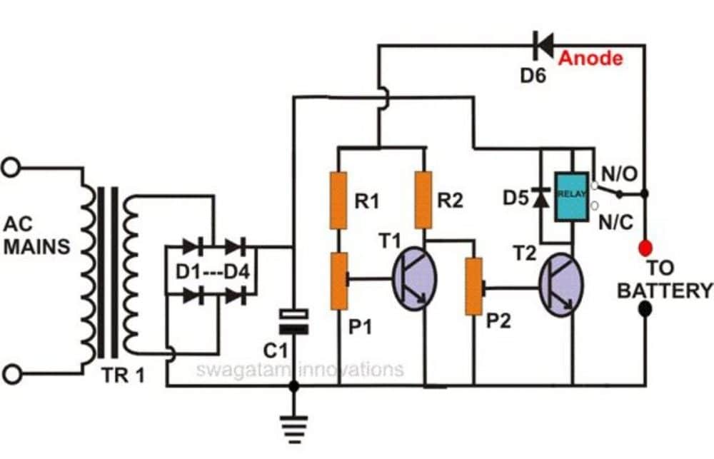
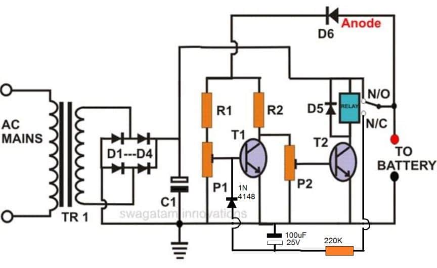
In this post I have explained how a neat little self regulating automatic battery charger circuit can be made using just two inexpensive transistors.
This circuit will automatically regulate the charging supply to the battery depending on its charge level, by switching the input supply ON and OFF periodically.
How it Works
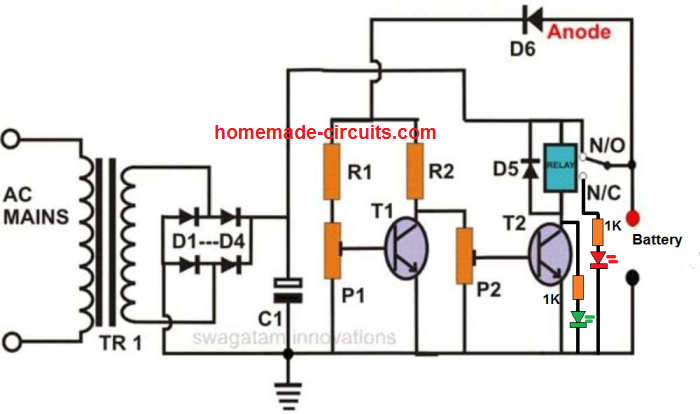
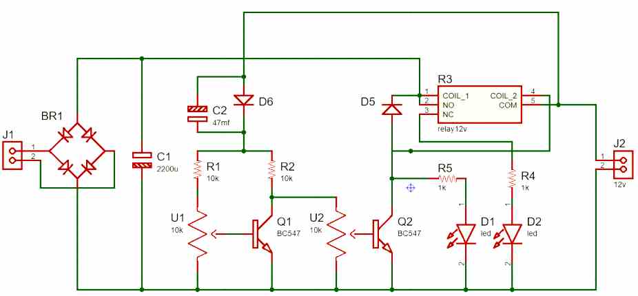
As can be seen in the diagram, this auto-regulating battery charger circuit utilizes just two transistors for detecting the charging thresholds, and cuts off the process as soon as these limits are detected.
Using two transistor actually makes the design hugely sensitive compared to a single transistor charger circuit.
The indicated preset is set in such a way that the T1 is just able to conduct at the specified full charge threshold of the battery.
When this happens T2 begins switching OFF, and ultimately at a point it is unable to sustain the relay conduction and switches OFF the relay, which in turn cuts of the input charging source with the connected battery.
Conversely, when the battery voltage begins dropping, T1 gradually deprived of its adequate conduction voltage level, and ultimately it ceases to conduct, which quickly prompts T2 to initiate its conduction and trigger the relay into action,
The relay now reconnects the charging input supply with the battery, and restores the charging process until it yet again reaches the full charge threshold, when the regulating cycle repeats itself.
How to Sep Up the Circuit
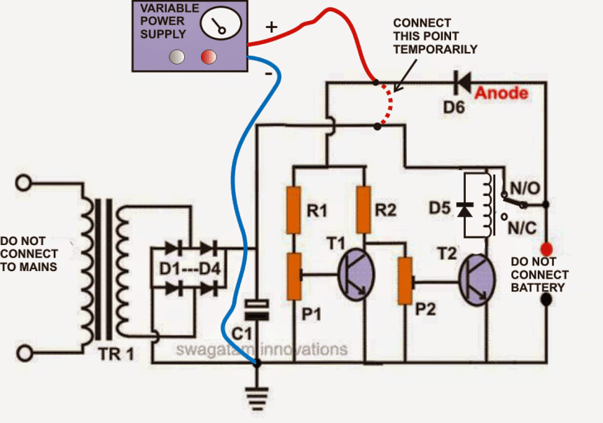
Setting up this battery charger circuit for automatic regulation is very simple and may be done in the following way:
- Initially, do not connect the fixed transformer power supply; instead connect a 0-24V, variable supply voltage to the circuit.
- Remove the anode of D6 from the relay contact and connect it to the positive of the power supply.
- Keep both the presets somewhere at the center position.
- Switch ON the power and adjust the voltage to 11.5 volts or lower.
- Adjust P2, so that the relay just activates.
- Now increase the volts to about 13.5 volts, and adjust P1 so that the relay just deactivates.
The setting procedure of the circuit is now complete.
Check the whole procedure by continuously varying the voltage up and down.
You may now remove the variable power supply and connect the fixed transformer, bridge power supply to it.
DON’T FORGET TO RECONNECT THE ANODE OF D6 BACK TO THE RELAY CONTACT OR THE BATTERY POSITIVE.
The battery connected to this circuit will be charged only as long as its voltage is in between the above "window" level.
If the battery voltage crosses the above "window", the relay will trip and stop the battery from charging.
Parts List
- R1, R2 = 10K = 2
- P1, P2 = 10K PRESET = 2
- T1, T2 = BC 547B = 2
- C1 = 2200uF/25V = 1
- C2 = 47uF/25V (Please connect this capacitor across the relay coil) = 1
- D1---D4 = 1N5408 = 4
- D5, D6 = 1N4007 = 2
- RELAY = 12 VOLT, SPDT = 1
- TRANSFORMER = 1, (AS PER THE CONNECTED BATTERY AH (DIVIDE BY 5)
The following diagram shows the instructions which needs to be followed while setting-up the circuit with the desired cut-of thresholds, using a variable power supply unit:
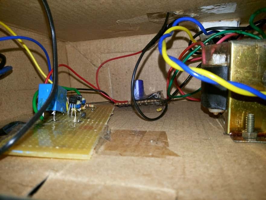
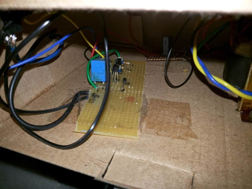
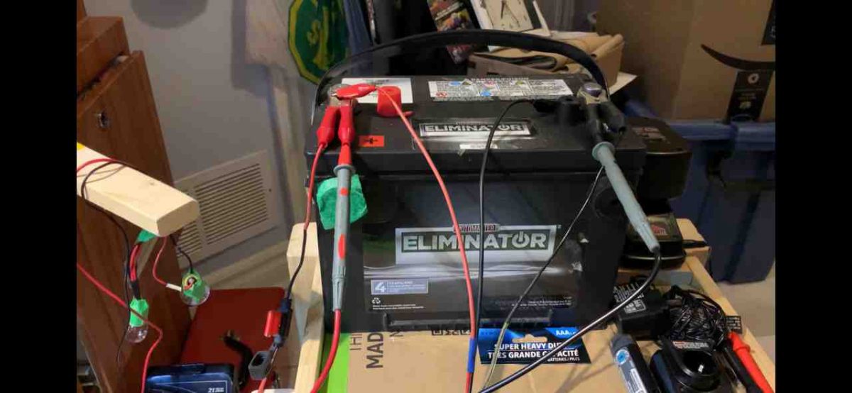
The above self-regulating battery charger circuit was successfully built and tested by Mr. Sai Srinivas, who is just a school kid but nevertheless has an immense interest in the field of electronics.
The following images were sent by him which displays his talent and intense dedication in the field.
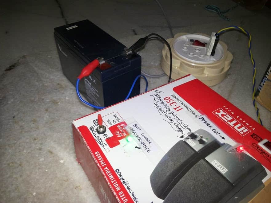
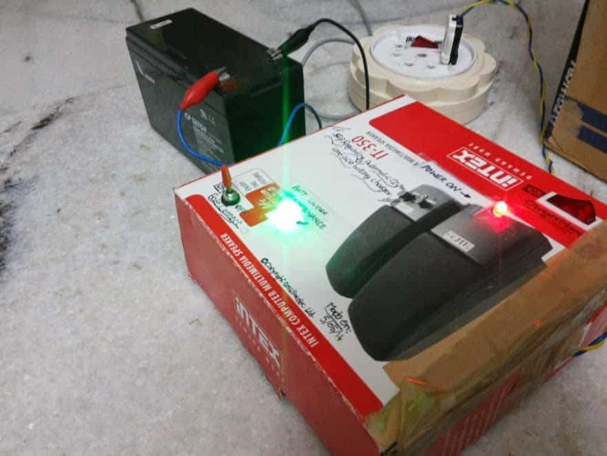
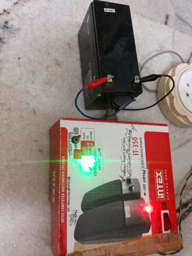
For One Shot Operation
If you want the above circuit to lock itself into a permanent cut off position when the battery is fully charged, then you may modify the design as shown below:
Note: To ensure the relay does not latch itself quickly on power switch ON, always connect the discharged battery first across the shown terminals and then switch ON the input power.
In order to indicate the charging status of the battery, we can add a couple of LEDs to the above design, as shown below.
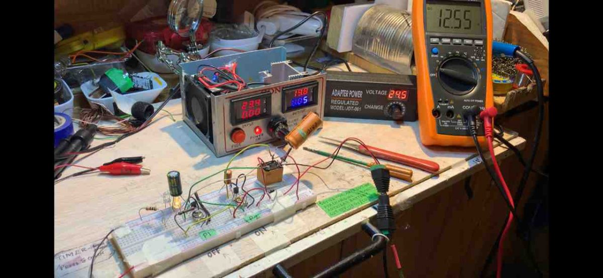
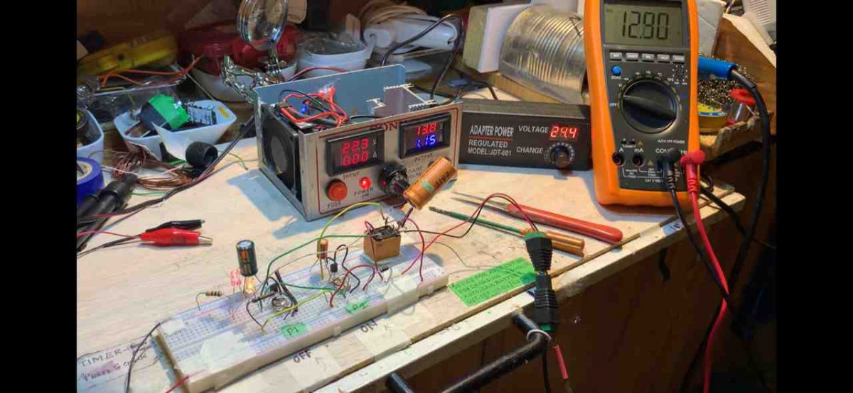
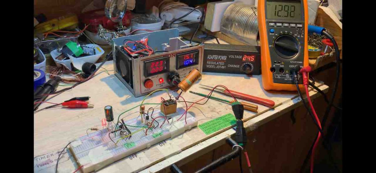
The above circuit was also successfully built and tested by one of the dedicated electronic enthusiasts from this blog. The following pictures verify the results:
Warning: Make sure to test the preset setting thoroughly before you leave this application unattended. And be sure to use only 14V as the input supply for a 12V battery.
Formulas and Calculations
Full-Charge Cutoff Voltage
The voltage at which charging stops is calculated as:
Vcutoff = VBE(T1) + (P1 / (R1 + P1)) * Vsupply
For example:
Full-charge voltage (target) = 13.8 V
VBE(T1) = 0.7 V (for silicon transistors)
Vsupply = 15 V (after rectification and, filtering)
To achieve a cutoff of 13.8 V you can set the divider network:
13.8 = 0.7 + (P1 / (R1 + P1)) * 15
Rearranging for P1 / (R1 + P1):
P1 / (R1 + P1) = (13.8 - 0.7) / 15 = 13.1 / 15 ≈ 0.873
Choose R1 = 1 kΩ.
Then: P1 = 0.873 * (R1 + P1)
P1 = 0.873 * (1000 + P1)
P1 ≈ 687 / 0.127 = ~6.87 kΩ
Set P1 to approximately 6.8 kΩ.
Reactivation Voltage
The voltage at which charging restarts is calculated as:
Vreactivation = VBE(T2) + (P2 / (R2 + P2)) * Vsupply
For example:
Reactivation voltage = 12.6 V
VBE(T2) = 0.7 V (same assumption as above)
Vsupply = 15 V
To achieve a reactivation voltage of 12.6 V:
12.6 = 0.7 + (P2 / (R2 + P2)) * 15
Rearranging for P2 / (R2 + P2):
P2 / (R2 + P2) = (12.6 - 0.7) / 15 = 11.9 / 15 ≈ 0.793
Choose R2 = 1 kΩ.
Then: P2 = 0.793 * (R2 + P2)
P2 = 0.793 * (1000 + P2)
P2 ≈ 793 / 0.207 = ~3.83 kΩ
Set P2 to approximately 3.9 kΩ.
Relay Activation Current
The current needed to activate the relay is:
Irelay = Vcoil / Rcoil
For example:
Vcoil = 12 V (relay coil voltage)
Rcoil = 400 Ω (typical relay coil resistance)
Irelay = 12 / 400 = 0.03 A (30 mA)
Filter Capacitor Value
The filter capacitor smooths the DC and is calculated as:
C1 = Iload / (2 * f * DeltaV)
For example:
Iload = 1 A (charging current + circuit consumption)
f = 50 Hz (mains frequency)
DeltaV = 2 V (acceptable ripple voltage)
C1 = 1 / (2 * 50 * 2) = 1 / 200 = 0.005 F = 5000 µF
Choose C1 = 4700 µF or 6800 µF... for sufficient filtering.
Hysteresis Voltage
The hysteresis prevents frequent relay switching and is calculated as:
V_hysteresis = V_cutoff - V_reactivation
For example:
V_cutoff = 13.8 V
V_reactivation = 12.6 V
V_hysteresis = 13.8 - 12.6 = 1.2 V


Questions & Answers
is there any way that it can use only one RED LED.
where if it cut off, the RED LED will be off. without switching or cutting from RED LED to Orange?
Remove the two LEDs shown in the last diagram, and connect a single LED in series with the base of the T2 transistor.
Just stumbled upon your very helpful circuit of self regulating battery charger. Please what is the value and type of the diode used in the alternative circuit without relay I mean the one connected to the base of TIP122? Is it a silicon diode? The circuit was last updated on May10, 2021. Thanks for your kindness.
Thanks for responding. I am referring to the reply you sent to Vee on May I 2021 where you posted an alternative circuit diagram using a diode connected to a TIP 122 transistor to replace the relay and the 2nd transistor in the original circuit, thus making it a solid state self regulating auto cut off battery charger. I tried to copy and send it you but didn’t succeed. Thanks again.
OK, understood. However, after a deeper investigation I realized that this circuit had some issues, so I replaced it with a better alternative.
Here’s the link for the new solid state self regulating battery charging circuit, which you can try:
Thank you very much Swagatam. Very happy that people like you are still on this earth. I wish you more knowledge and strength.
Thank you Robert, I am always glad to help!
Hi, thanks, can you please specify which circuit diagram are you referring to?
I cannot see any circuit without a relay…
What is the purpose of C2 ? Will this circuit work without it, and why isn’t shown in the circuit schematic ..?
It is to ensure that the relay does not chatter while switching….it is important to attach this capacitor parallel to the relay coil.
Thank you Swagatam, I thought that’s what D5 was for, but I can assure you I will install that capacitor for good measure ..! Thank you so very much for sharing this circuit, I was trained as a technician and have very limited knowledge of circuit design, thanx again for your help, best regards-Mark
You are welcome Mark, D5 is for shorting out the reverse voltage spikes generated by the relay coil and thus prevent the transistor from getting damaged. For C2 please make sure to use a higher value capacitor such as a 220uF or a 470uF which will ensure smoother switching of the relay. Wish you all the best!
Thanx for the capacitor values and I really appreciate your lightning ⚡️ fast response ..!
I am glad to help!
greetings…!!!!
Hi dear Swagatham,
Its so inþeresting your circuit.Regarding the first circuit once the max chaeging voltage reach the relay will cut off then when will start the charging automatically again?ie..when 13.8volt set to cutoff then termiñal voltage become low then will it start immediately hence chance for a chattering relay.can we adjust the lower threshold (the point which charging voltage to start again )in any way?expecting your valuable advice.
from Kerala with ❤❤
Thank you Sison, The relay will not chatter actually, rather switch ON/OFF within a span of maybe 4 or 5 seconds.
The switch ON threshold can be perhaps increased by adding a hysteresis to the circuit.
I have tried this through a feedback link, as shown in the second last schematic.
Owkey sir thanks to reply me!!!
But could u send me your whatsap contact so that u can see easy what I did. Because I used 10K pot which is 103 is real it is exact pot needed? If possible please
Sorry Kadama, providing watsapp number may not be possible. 10k pot will not work correctly, instead you must use a 10K preset, preferably a multiturn type.
you ask me: how many volts and amps is the input source, how do I connect the capacitor C2 that I don’t understand, can you guide me? I really need this, thank you
Input V and I of the supply will depend on the battery specs. Connect C2 in parallel with the relay coil or D5….positive of the C2 will go on the positive supply line, and negative of C2 will go to the lower terminal of the relay which is connected with the transistor collector
I drew the circuit of the battery charger to disconnect automatically according to your diagram, can you check it for me, my battery is 12 volts and 7.5 amps, thank you
C2 must be connected parallel to D5, not D6….the relay connections look messy so I cannot comment on that!
my battery is 12 volt 7.5 amp, so what is the V and I I use, I drew the circuit, I sent it to your email, can you check it for me?
You can use 12V, 1 amp transformer, which will produce around 16 after full bridge rectification. Sorry, I do not communicate through email, if you are having problems with the above schematics please specify about it here.
hi, I drew a printed circuit using Proteus software based on your schematic, I want to send it to you to check for me but it doesn’t work, my source is 15 volts 7.5 amps, now I want to charge it what to do for my battery, thank you
Hi, I cannot suggest about the Proteus results, but practically the circuit works nicely, I have tested it, and many others have also tested it successfully. However if you want an easier op amp based design I can also provide that
Na lista de peças fala em C2, mas não é indicado no esquema. Agradeço indicação como ligar.
Obrigado
You must connect C2 across diode D5 or the relay coil. positive of the capacitor will go the cathode of the diode D5, and negative of the capacitor will go to the anode of the diode.
Hi Swagatam
I managed to play around with the above circuit and got the switching – off to on – to about 1 minute 35 secs approximately by adding a 2200 mfd capacitor across the relay and a 1000 mfd across the base emitter of T1 and a 100 mfd across base emitter of T2. So now its not like fast flip flop.
From a discharged level battery it charges up and cuts off at about 13.0 volts and then cycles between 12.55v to about 12.92v.
And I also changed the connections a bit on the Relay. I connected the Common to the positive of the relay and NO to the battery, works fine.
I tried sending you pictures of the project to your email but got a failure reply saying this email does not exist.
Thanks for all your guidance and help, hope you find this ok
Please reply
All the best till the next time
Regards
Vee
Thank you Vee, appreciate your kind feedback
Glad to know the circuit is working OK for you now!
You can send the images to hitman2008 @ live . in
Thank you very much Vee…got all the images, and I will soon publish them all in the above article.
Hi Swagatam
I must thank you immensely for all the help and guidance you have given me and for your precious time and patience.
Im so blessed to have you as a friend in this field of electronics for which I only as a hobbyist have a passion even at this old age,to pass my time in these crazy times bless you,
Thanks for also sending me an alternative circuit which I would try when I am able to get the TIP 122 . Is this also a SELF REGULATING or AUTO CUTOFF
Thanks again Swagatam
All the best to you
Can I send you a picture of my project by email to you, please let me know ok
Vee
Yes definitely….you can send the pics to my email…hitman2008 @ live . in
It is my pleasure Vee, I am always happy to help.
Yes the transistor circuit would work exactly like the relay circuit, but without making any noise, it would silently keep doing the flip flop switching at the battery full charge threshold, and make sure the battery never gets overcharged…
Hi Swagatam
Good news
I managed to get the circuit working finally the only thing is when adjusting the cut off voltage and cut in voltage it keeps switching on and off like a flip flop so fast when I switch off the power supply and back again then its stable but it happens now and then
I added the caps between the base and emitter of the transistors
I know it takes very minute adjustments of the presets
I has to discharge the battery several times down to about 11 volts and try and it recharged quite fast with the power supply I have, recharges at 1.15 to 1.2 amps and goes down to about 250 ma in about half an hour to 13.8 volts
Thanks again for all your help
Regards
Vee
That’s great Vee, at least you could get the circuit to work ON/OFF at the threshold.
If you connect a 1000uF right across the relay that might prevent the relay from self regulating too fast.
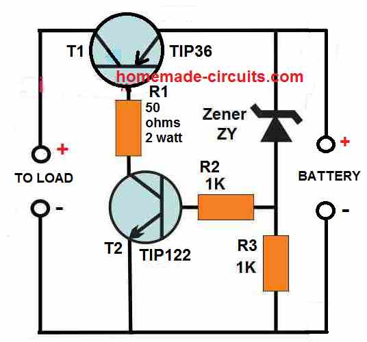
Alternatively you can completely get rid of the relay and use only the transistor stages to charge the battery in a solid state manner….here’s the modified diagram for you:
You can replace the T2 with a TIP122
Hello swagatam.
Can you write how to make the settings of the transistor circuit?
Hi Suat, the setting procedure is the same as described in the article.
Hi Swagatam
I know you said the relay connections are exactly as shown in the diagram but I am a little confused with the labelling as you only show NC & NO & not the C
So I want to know if the connection to the battery and the anode side of the diode is on the NO side of the relay and the Common is to the positive side of the relay
Please reply
Thanks
Vee
Hi Vee, the common pole of the relay is connected with the battery positive and the anode of the diode D6, the N/O of the relay is connected with the positive supply line of the circuit. The N/C point is blank.
Hi Swagatam
Thanks for your reply shall do as you have told me
The car battery is 640 Cold cranking amps Reserve is 85 Amps
The Power supply is a variable 4.5 volts to 24 vdc 2amps I also have a 3 Amp one Its set to 14.0 volts
Are these ok or do I have to have higher amps power supply
I tried these power supply with a Auto cutoff circuit of yours using a BC547 or 2N 2222 and the battery charges well intially at about 1.2/1.3A and slowly reduces to about 200 ma and cutoff when the battery is at 13.8 volts , works good
But I am curious to see how this SELF REG. circuit works …… anyway shall try again aa you instructed me
Thanks Swagatam for your help
Vee
Hi Vee, for a 85 Ah battery 2 amp current is too less, and it might take at least 24 hours for the battery to get fully charged.
The above circuit was tested by many of the visitors successfully so the circuit will work although it might require some skillful adjustment of the presets.
Hi Swagatam
I tried the above circuit (self regulating charger) but I still could not get it working
Is the common contact of the relay connected to the anode of the diode and the positive power supply connected to the NO of the relay
When I tried doing the initial settings as per your instruction there is no response on the relay.
I am using a 12 volt cube relay whose coil resistance is 410 ohms
I also tried transistor BC 547 and also 2N 2222 ( pinout is opposite to 547)
Power supply is from my variable bench supply set as per your instructions
Please help
Vee
Hi Vee, yes the relay connections are exactly as shown in the diagram.
You can set up the circuit in the following way.
Keep the slider of both the presets to ground.
Switch ON transformer supply, and then connect a discharged battery to the relay contacts as shown in the diagram.
Now slowly adjust P2 until the relay clicks ON….now the battery will start charging.
Monitor the voltage with a voltmeter until the battery is fully charged.
As soon as the battery is fully charged, slowly adjust the P1 preset until the relay just clicks off.
Your setting up procedure is now complete.
Connect a 100uF capacitor across the base/emitter of both the transistors to stabilize the relay contact operations.
Remember the transformer current must be 10 times less than the lead acid battery Ah rating.
Hi Swagatam
Sorry for troubling you, I was thinking if I could use a bypass transistor like the MJE2955T with the LM 317 to get a higher current output and can i put them on the same heat sink or should they be isolated this 2955 is rated 60V /10A in a TO-220 package will this work for a variable voltage of 1.5v to about 24.0v and 10 amps . I have this transistor.
Appreciate your reply
If I want to send you the circuit which you would definetly know just to be sure I have it right how do i do that .
Thanks
Vee
Hi Vee, It will work but not with 10 amps rather only 5 amps max.
And please, I want you to ask these question under a LM317 or any power supply article, because the above self regulating charger is about battery charging so our discussions are off-topic, right?.
So please ask under a LM317 article or any power supply, I will try my best you solve your queries.
Hi Swagatam
Sorry about being off topic I was not aware how this works I shall pic as you say the related topic and ask my doubts
Sorry about that
Regards
Vee
Hi Vee, you can put your LM317 questions under any of the following articles:
https://www.homemade-circuits.com/?s=LM317
Hi Swagatham
I told you earlier I had made a Variable voltage supply using the LM317 and that is working fine but can only handle 1.0 amp so I tried using an LM338 which I got from China as no store has it locally. Using the same circuit as for the LM 317 I tried replacing it with an LM338 using the same power supply as in the earlier LM317 circuit but there is a bit of flicker and the IC fails and pin 2 & pin3 get shorted out. I put back the LM317 and it worked fine with the same load of about 600 ma I tried again with the LM338 and this to burnt out in seconds
I would like to send you the circuit so you tell me it it’s suitable for both IC ‘s ……. should I send it by email to you please advise
Thanks
Vee
He Vee, that clearly indicates that your LM338s are not good, they may be faulty internally or maybe duplicates.
Instead of using LM338, you can try putting 2 or 3 LM317 in parallel, and mount them over a common heatsink and close to each other. that should effectively work like an LM338 equivalent.
Hi Swagatam
Thanks for your reply, I was considering doing the same as you advised about paralleling 2 or 3 LM 317’s do i have to have any resistors small value at the out puts, can i do 4 of them and if possible can you send me the diagram and this will need a real big heat sink. Do I have to have a minimum load connected to it to avoid over voltage at startup
Thank you very much Swagatam fir all your help if possible you can email me the parallel circuit, I know how it should be but just to make sure Im on the right path and is it ok if I am using a 24 volts /6 amps SMTP adapter or should I use a conventional transformer
Thanks
Vee
Hi Vee, there’s nothing you have to do in the circuit, except connecting the IC pins in parallel, but make sure to connect the ICs over a common heatsink, very close to each other.
Thanks Swagatham
I’ll do as you have advised me
All the best to you
Regards
Vee
You are welcome Vee!
Thanks for your knowledge shared. I will try it. But sir, can it be used on a 12v 200ah inverter battery? Please answer me thanks
Are you referring to the following new post:
Simple SCR Battery Charger Circuit
No sir I’m talking about the Self Regulating Battery Charger Circuit
You can use any battery for charging with the above circuit, regardless of the Ah value, you will only need to suitably upgrade the relay specifications in accordance with the charging current of the battery
Hi Swagatam
Thanks immensely for your prompt reply and help in providing me with some long duration timer circuits, shall try them out and let you know if i did it right
Thanks again
Vee
No problem Vee, I am always happy to help!
Hi Swagatam
I wrote to requesting you to give a circuit for a delayed relay timer of 10 minutes to 2 hours, I have made one from 10 mins to 1 hour with IC 555 but this has I understand a limitation of capacitor of upto 2200 uf
I would appreciate if you could give me a circuit whenever it’s possible by you
Thanks
Hi Vee,
you can try one of these circuits:
https://www.homemade-circuits.com/how-to-make-simple-versatile-timer/
Hi Swagatam
I need some help with converting an ATX to a bench power supply.
I have written to you earlier about your selfregulating battery charger etc and have followed your instructions and got them working and thank you for the same also built a variable power supply and other projects & working good
I am a 70 plus years older hobbist and love doing small electronic projects to keep myself busy and pass my time usefully, I have been interested in electronics for many years and happy to get to know you on the net.
The present problem with the ATX is I have tested it with the power ON switch and the little push switch which turns on the fan and the voltages at the several plugin terminals …….
Orange PG 3.3 v ……. Red + 5.1v ……. Yellow +12.2 v ……. Blue — 12.2v and White — 5.1 v ….. blacks …return/ grd.
When I tried to see if power was really there with a 12 v /10w bulb it did not light up so I added a load resistor 10 ohm 10 watts between the Red and white I guess by mistake then the light came on the resistor got hot and the ATX went off
I should have connected the Red and black to the Resistor I think. Now when I switch on the Power the fan just jiggles and nothing happens . Is there anything I can check or do to get it working or have I made it a paper weight ????
Please reply ……. sorry for the long story
Thanks in advance
This is an old SAMSUNG Model PSCD151404A ATX
Hi Vee, I appreciate your efforts and your interest very much in the field of electronics. I am glad you could build a few of the projects from this website.
For converting your ATX into a bench power supply, you just have to feed the bench power supply output to a regulated bench power supply module. This may be done through a rotary switch for selecting the different ranges of input to the bench power supply module.
Here is a link to the construction of a bench power. The transformer and the bridge section could be eliminated, and replaced by the various outputs from the ATX via a rotary switch:
How to Design a Stabilized Bench Power Supply Circuit
Hope this idea proves useful to you!
Dear Swagatam
Thank you very much for your immediate reply which I appreciate.
I do know I have to either put a rotary switch or have multiple binding posts for the different voltages etc.
If you read the last portion of my message you will see what happened when I was testing it , the ATX Power went dead and when I tried to switch on the power again the cooling fan just jiggles (shakes) but does not run and there are no voltages at any of the leads . So I need to know if any of the IC’s would have shorted out or what should I check or do to get it working again . I checked the 4 amp fuse is ok. So please see if you can guide me where to check etc.
Thanks for your kindness and help, may you be blessed in all your endeavours
Regards
Vee
You ae welcome Vee…
ATX involve SMPS circuits which can be difficult to troubleshoot without a proper test equipment or without practically viewing the circuit.
If you think your ATX is burned then it can be quite difficult to diagnose the fault, unless you are well versed with the working of AC SMPS circuits.
Most probably the MOSFET might have burned, so you can try checking the MOSFET or any big power device associated with the circuit, and see whether it is alright or not…
Thank you for putting yuor ccts on net
Thank you for your kind feedback!
Hai sir..
I try this circuit for my 12v battery.
I adjust preset for low & high voltage threshold.
Relay ON in 11.50V & OFF in 13.90V
Voltage reaches 13.90v the relay turn OFF.
Now the battery voltage will decrease..in 13.20 v the relay is turn ON & charging.. But i set 11.50v to start charging… Pls guide me sir
Hi Kesavaraj,
As mentioned in the title, this is a self regulating battery charger, meaning it will try to restore the charging process as soon as it detects the battery has deviated from the optimum charge level. The single transistor cannot detect or “remember” the preset setting accurately as op amp would do. So what you are seeing is correct, the circuit will keep restoring the charging as soon as it detects a deviation of around 0.5 V or more.
You can try the feedback system as described in the last diagram for increasing the low/high cut off threshold margin. And you can also try using high quality multiturn type preset, which can also help to improve the hysteresis effect
Thank you sir
Dear Swagatham
In your circuit for ‘ Self regulating battery charger you show that the positive side of the relay is connected to the NO contact of the relay, is this correct or should it be the Common contact as I tried it as per your circuit but it does not work
Kindly reply
Dear Vee, the circuit is correct, the positive charger supply is connected to the N/O of the relay.
The circuit will respond only when a battery is connected.
When you connect a battery, the battery voltage reaches the R1, R2, and goes to the base of T2 through P2. This switches ON the relay, and moves the contact to N/O, which connects the battery with the charging supply from the transformer.
Please check your circuit connections and the preset setting.
Thanks Swagatham for your reply
Connections are as per your circuit which I did on a bread board and I have a 18 volt variable power supply which I used to try doing the setting as per your setup instructions but there is no response neither the LEDs or the relay goes on, I don’t know where I’m wrong …… please advise ……. Thanks
Hello Vee, First of all you must try the circuit on a strip-board by soldering all the parts correctly, a breadboard may cause loose connections and confusions.
For faultfinding, you can check the base to emitter voltages of the two transistors, this will confirm whether the transistors are responding or not.
Or you can connect LEDs in series with the bases of the two transistors which will enable you to see how the transistors are conducting in response the preset adjustments and supply voltage variations.
Really appreciate your valued input and technical brain engaging circuits. Would you kindly include 24vdc and 48vdc sequential or alternating charging circuits not limited to transistors but including thyristors and mosfets
Thank you very much! You can use the same circuit for 48V or 24V just by upgrading the R1, R2, the relay and the power supply section. If possible I’ll try to update the design soon….
Hello Mr. Swagatam. I have 6 serial connected Lead acid accumulators. Need auto cut-off charger. Can you help me?
Hello Levent, series connected batteries can be charged together, but we cannot guarantee if all the batteries would be charged uniformly, so you will have to connect the charger to individual batteries separately for ensuring that all the equally charged. You can try one of the following designs:
Lead Acid Battery Charger Circuits
pls, i want to design a power bank of high Mah rating..i want it to charge from normal phone charger and also a solar panel(i currently have one small one, output volt is 6-7volts) but i want it to have auto battery detection….but be as compact as possible
i just dont know how to begin the design..can you pls help??? and with a detailed explanation
you can try the second concept from this article:
https://www.homemade-circuits.com/battery-current-indicator-circuit/
you can feed the solar and phone charger DC inputs both together through separate diodes to the input of the LM338
Sir l’m talking about the diode in this self regulating battery chager in this artcle which other diode is rated 10
youngking, if your battery is 50 Ah then the Bridge rectifier diode will need to be at least 10 amp. LM358 cannot be used for those mentioned ICs,
Sir I want to design this charger circuit for a 24v battery,any changes to the circuit??
No change in parts except the relay and the transformer which must be 24 v rated.
good day sir , pls can u named the diode that is rated 10amps. also can one use lm 358 in place of lm 350, 396, 338 then other ones that can handle 10amps current. waiting for ur response
Youngking, please post the question under the article that you are referring to, so that I can check to the diagram quickly
Do you have a schematic for a self charging Bluetooth speaker type design? I am taking a electric class and the teacher says to have a project in mind, I want speaker which charges itself when it’s low
The charging can happen from a source, such as from a AC mains input. Do you mean an automatic charging?
Yes like a self contained charge. I don’t want to have to plug my speaker in Everytime it dies, I want it to keep it self charged when it hits a level it charges back up to full. I think that’s the one you sent me.how would I add a blue tooth speaker into the mix
In that case you can try the second concept from the following article:
https://www.homemade-circuits.com/how-to-make-current-controlled-12-volt/
Ignore the trasformer and the meter, use only the transistor resistor, zener diode for the operations. Just make sure the output across the emitter and ground of the transistor is 0.7V higher than the full charge level of the battery. Set this without any battery connected. This may be set by tweaking the zener diode value appropriately.
sir thank you for your hard effort, God bless you
You are welcome!
hello sir ,there is question I ask u concerning this self regulating battery charger which how to involve two led one to indicate battery charging and another led ted to indicate when battery is fully charger. and here was your reply.” Connect one LED from N/C to ground, and other from N/O to ground, via 1K individual resistors now my first query is (1..) is it to add the 1k resistor to the anode before connecting it to N/C. 2. if I’m using 75ah battery what modification will I make in this circuit. 3. u said that when charging lead acid battery that the current and the transformer should be 1/10th of the battery. pls can u explain this with an example. am waiting for your responds.
Hello youngking, I have updated the LED diagram at the end of the post, you can check it out. For 75 Ah, just make sure the relay contacts can handle upto 15 amps or more, and make sure the transformer current is not more than 10 amps.
For knowing the charging current details, please refer to the following article:
https://www.homemade-circuits.com/high-current-10-to-20-amp-automatic/
hello sir, I came across your circuit tittle “Single Transformer Inverter/Charger Circuit” can this approach be use in an inverter using ic. I didn’t see the commen t box that is why I comment through this medium.
Hi Favor, yes it can used for any inverter, you just have to change the transistor oscillator section with your IC based oscillator.
thank you sir, I will try
Hello sir, to wind for battery charger what value of secondary turns for 12v battery to get 14.4v after rectification should I base Es 12 or 14.4 to calculate the number of turns.
sir how will one add 2 LED to indicate when the battery is fully charge and low battery, can 5amps transformer be use in charging 12v 75amp battery with the above circuit .
Connect one LED from N/C to ground, and other from N/O to ground, via 1K individual resistors
Pls, sir what are the applications of this 12v self-regulating battery charger?
Thank you
Please sir what is the function of relay in this circuit.this is a question from one of my lecturer in my school.
Timmy, the “Relay” indicates the relay coil. The points connecting the “Relay” should be replaced with the relay coil terminals in the practical circuit.
Hello sir in ur post where( one transistor auto cutt off charging cricuit).. Comment option not show… Can i comment the previous point in this post…
Apurva, post your questions here:
https://www.facebook.com/swagatam.majumdar.7
Sir Good Day, can i use d882 transistor for T1 & T2 instead of bc547? the stores here has run out of stocks..
I have 12v 4amps transformer & a 12v 20AH battery to be charge..
Thanks
Good day Paul, that will work but will be an unnecessary overkill. Instead you can try 2N2222 or 2N3904 or any small signal transistor similar to these.
Thanks for the reply sir.. is C945 be ok to be used in T1 & T2?
& where can i put full charge indicator? where to put the anode & cathode of the LED bulb?
Thanks again sir..
Hi Paul, yes C945 will be good, be careful with its pin orientation, it’s completely different to BC547…you can put an LED between the emitter of T1 and the ground line. Anode will connect with the emitter of T1 and cathode with the ground line.
Make sure to connect a 1000uF parallel to the relay to prevent stuttering of the relay at the thresholds
Thanks Sir.. How to setup up the autocut off of this circuit using C945? is this procedure still applies to it?
Initially, do not connect the fixed transformer power supply; instead connect a 0-24V, variable supply voltage to the circuit.
Remove the anode of D6 from the relay contact (common contact) and connect the cathode to the positive of the power supply.
Keep both the presets somewhere at the center position.
Switch ON the power and adjust the voltage to 11.5 volts or lower.
Adjust P2, so that the relay just activates.
Now increase the volts to about 13.5 volts, and adjust P1 so that the relay just deactivates.
The setting procedure of the circuit is now complete.
Thanks Sir..
Thanks Sir.. ill try to make the circuit.. is setting the cutoff threshold the same procedure Sir?
Hi Paul, yes the setting up procedure will be the same, it is not related to the feedback loop.
Thank you very much Sir.. ill wait for your update sir.. Thank you very much again..
Hi Paul, I have updated it at the end of the post….
Sir there would be no changes in the circuit just connection of 100K resistor feedback link from N/C of the relay to the base of T1?
Paul, sorry, please ignore this idea because that may cause permanent latching when power is first switched ON, so it won’t work, I’ll try to figure it soon and update it for you
Thanks Sir.. Sir what modification can be done if i only want the cut-off function & remove the lower threshold limit function..
Hi Paul, to achieve this, you can connect a 100K resistor feedback link from N/C of the relay to the base of T1
Hi Paul, yes the procedure will be the exactly the same no matter which transistor is used
hai sir
i want to change my 12v 17 ah battery for my bike. what is the trsformaer sec voltage. i had a 12-0-12 3A trsformer is it enough for that and if i want to put low adjust from 11.5 to 12.5 what i want to do. please advice
Rajesh
Hi Rajesh,
12.5V is not the optimal charging level for a 12V battery, it should be 14V.
You can adjust the circuit in the following way:
In the second diagram, keep both the presets to ground level initially.
Adjust the variable supply to 11.5V, and adjust the right side preset such that the relay just switches ON.
Now increase the voltage to 14V, and slowly adjust the left side preset until the relay is just switched OFF.
seal both the presets with superglue.
Yes the transformer would be fine to charge your battery
hai sir
i meant that the battery comes 12.5 the charging needs to starts and stoping with 13.8 . for this adjustment what i need to do. can i use bd139 instead of bc547 because bd 139 is ready available with me.
do have any other same circuit using with out relay. i mean using other kind of active switching devices.
with the same starting and stoping voltage range.
Rajesh
OK, then you can try the first circuit from this article:
https://www.homemade-circuits.com/solar-charger-circuit-using-transistors/
but it does not have a low restore selection, the battery will be cut of at the high 13.8V and restart at 13V, this will go on continuously. BD139 cannot be used because it won’t handle 2 amp.
hai sir
last time I tried with bc 547 and it is getting very hot..so I thought it requires high current transistor..
rajesh
yes ..I am with you in your circuit you are using two bc 547b transistor one is for sensing and other one is driving the relay ..I am taking about the second one which one is driving the relay..it is getting hot .. that y I asked
rajesh
that could be because you may be using a high current relay, make sure the relay coil resistance is above 200 ohms, and make sure to use a diode across the relay coil.
Hi Rajesh, none of the circuits which I referred use BC547 for charging the battery, BC547 is used only for sensing and cutting of signal to the power transistor or relay. It is the power transistor or the relay which actually handle the battery supply
hello sir, i need a help from u i need an automatic 12v battery charger with following features;
1. battery level indicator
2. during charging process, the indicators (LEDs in series) will be blinking one after the other according to the level of the battery during charging
3. and when the battery is full the charger cut the charging process and the level/status indicator continue to work
Hello Solomon, I have updated the diagram in the following article
https://www.homemade-circuits.com/3-step-dc-voltage-level-monitor/
for the cut-off facility you can further modify in the following manner
https://www.homemade-circuits.com/universal-battery-charger-circuit-with/
I’m very grateful.
But more questions: At 1threshold current=20A
I have calculated my
(a)R1=35.75ohms (approx 36ohms)/6.25W or 6W
(b) R2=0.04ohms /14Watts
Q(1) where will my TIP35 collector be connected in my self regulating charger circiut
Q2(2)will 15v DC be able to drive the TIP35 bcos Vcc is 20v from datasheet or it that the max
Q(3) how can I use MOSFET to replica the work of the relay in case I can’t find 30A relay
Thanks for your timely response
TIP35 and 2N2222 are for the current controller stage, not for the above circuit.
Th above self regulating circuit will remain as is.
for a mosfet version you can try the second design from this article
https://www.homemade-circuits.com/make-this-48v-automatic-battery-charger/
In this design an external current control is not required since the BC547 stage will to do it for you
Thanks so much for your response.
Pls can you be specific to help me for the current control circuit of 20A and how to connect it to suit my design. Thanks
Hello Swag it seems you have lost track of my discussion. The immediate questions below come up as a result of the quoted reply from you.
I want to include the current controller in the “self regulating charger circiut”, is it possible? Or are you saying I should just convert the “48v charger circiut to 12v and limit the I=20 or 25A
” At threshold current=20A
I have calculated my
(a)R1=35.75ohms (approx 36ohms)/6.25W or 6W
(b) R2=0.04ohms /14Watts
Q(1) where will my TIP35 collector be connected in my self regulating charger circiut
Q2(2)will 15v DC be able to drive the TIP35 bcos Vcc is 20v from datasheet or it that the max
Q(3) how can I use MOSFET to replica the work of the relay in case I can’t find 30A relay
Thanks for your timely response”
This is your previous reply before the above questions.
“you can connect it between the main DC supply and the battery control circuit. the transistors can be TIP35 for the upper transistor and 2N2222 for the lower one. resistors can be calculated as per the given formulas.”
Hi Segun, I have not lost the track,
I am replying you correctly.
Earlier you asked me to provide a current control stage for adding to the above circuit right?
So I suggested you the following
https://www.homemade-circuits.com/make-hundred-watt-led-floodlight/
So the TIP35/2N2222 was referred for this linked circuit.
and yes the 48V charger concept can be converted for your 12V, if a mosfet version is required instead of a relay.
In the 48V version, just remove all the 22K and replace them with a link.
remove the IC pin#7 zener diode, and also remove the 4k7 at pin#3 of the IC
you can connect it between the main DC supply and the battery control circuit. the transistors can be TIP35 for the upper transistor and 2N2222 for the lower one.
resistors can be calculated as per the given formulas.
Good day, pls Intend to use this circuit for charging battery up to 200ah. My transformer is 255v/30A, my bridge rectifier is 50A, my relay is DC 10A/28v will that be ok?.
(2) what determines my max charging current.
(3) what fuse rating to use to protect the circuit from a load drawing more than design current
Thanks
(1) Do you have any current controller for me to use.?
(2) can the circuit also be used for lower battery say 7Ah
(3) hope the 30A relay will last?
you can use the circuit for any battery, by selecting a matching relay as per the battery specs.
for current control you can use the following concept
https://www.homemade-circuits.com/make-hundred-watt-led-floodlight/
Segun, for a lead acid battery the ideal rate of charging is around 1/10th of the battery’s AH rating, meaning your 200AH battery should be charged at the rate of 20 amps for around 12 to 14 hours, for allowing 95% charging.
that also implies the 10A relay will not be enough, you must change it with a 30A relay, and use a current controller in the middle to make sure only 20A is able to pass into the battery
I have a 12v 7ah battery but I don’t have proper charger right now to recharge it so I am connecting the battery directly to my home inverter to recharge it. Will it recharge correctly with proper current and voltage or it will destroy the battery.
a 12V/7ah battery will need 14V, 1 amp to charge correctly for 10 hours continuously…if this is not followed your battery will get damaged.
Hi sir, I want an auto cutoff lead acid battery with relay but I don't want ic and also I didn't get the common pin of relays in upper diagram and explain them please.
Abhishek, you can use the circuit which is explained in the above article. Just connect a 10K resistor from N/C to the base of T2, this will latch the relay as soon as full charge is reached.
the contact which is connected with D6 and the battery positive is the common pole
Hi sir, can you please provide me an automatic 12v lead acid battery charger without using relay, I have right now tip 122, TIP 127,and other components but I don't have relay so can you help me.
What if I charge it with 20v – 24v 1A instead of 14v 1A
Hi Aabhishek, you can try the following design
https://www.homemade-circuits.com/2016/05/how-to-set-ic741-battery-charger.html
Battery life is shortened if it's charged or discharged beyond it's safe limits, not due to charging it at 70% or 80%. Moreover here the charger is designed to self-regulate meaning it would keep switching On and OFF within a range of 0.5V to 1V, in other words between 14V and 14.5V for a 12V battery…and that's a good way of keeping the battery topped up.
A lead acid battery life can be maintained at maximum level as long as it's charged and discharged at 1/10th of its AH rating and within 11 to 14V for a 12V batt
I hope this enlightens you regarding the facts.
Swagatam, when you have the time could you advise on how to make this circuit more robust. I have a 25amp, 12 volt relay/contactor and some 2n3055 transistors.
I'm guessing this would call for different values for the resistors.
How would I calculate the new values?
Thank you in advance.
Carl
Thanks Carl for posting this interesting question, if you are intending to use 2N3055 transistor then the relay won't be required at all…and that would allow you to get a perfectly solid state version of the above…if possible I'll try to design it soon and post it here with the required hysteresis feature.
I got this circuit working.
It seems this device would be best used as a battery shut off if one didn't want one to discharge below a fixed voltage.
To be any use as advertised it would have to latch off at the high end and come on again at the low setting.
Used on a working battery it would spend most of it's time rapidly turning on and off maintaining the high value. Might as well use hydro in that case.
It might be useful providing a float at a lower voltage, would keep the relay busy with all that on and off business, though.
"Make this 48V Automatic Battery Charger Circuit" might fill the bill. I'll give it a try.
https://www.homemade-circuits.com/2012/08/make-this-48v-automatic-battery-charger.html
Thanks
Carl
Thanks for the update Carl, appreciate it a lot!!
yes, it will keep ticking at the threshold within a margin of 0.5V. that's the reason I named it as "self regulating" 🙂
it can be used at the lower switch-OF threshold or at the upper full charge threshold, depends on how the relay contacts are wired.
however to introduce a hysteresis feature you can experiment by adding a resistor from one of the relay contacts to the base of T2…as already discussed with Mr. Tim in my earlier comments…
BTY in Canada we call those presets, cermets
OK…got it.
Swagatam my man, do you build each of these circuits or do you run some of them on a simulator program?
If you run a program which one would you recommend, also is there a good free one?
Carl
yep, thanks Carl…
Mind simulation is what Tesla used….good for you…..It sure served him well.
Carl
Hi Carl, I never use simulators for checking my designs, to me those are just useless…I rely entirely on my mind simulation…which has been so far 99% correct, although the final result on some occasions require a bit of serious tweaking.
Could someone re-work this circuit so that one could plug any 12v charger into it and have it sense the battery voltage and turn the charger on and off as per the hi/low presets.
Carl
you can use the above circuit with any 12V charger input, once the preset is set it will respond to all charger inputs identically
Sir honestly speaking i have try the settings for the past 2hrs now, one setting always offset the other what I'm looking at doing is to use two relay one will be for cutoff while the other will be to trigger will this work please your advice is needed
Thanks and best Regards
Faith, try the last circuit from this article, for a low voltage actuation:
https://www.homemade-circuits.com/2013/05/low-battery-indicator-circuit-using-two.html
and connect a feedback resistor from the collector of BC557 to the base of central BC547…this will determine the high voltage actuation of the relay…
remember here the BC557 will need to upgraded for your 70 amp relay or if possible try with a smaller relay and confirm the results first
And yes but T1 and T2 are Tip22
use any small NPN for T12 such as BC547..and use a higher amp NPN for T2 such as a 2N2222 or D880 or 8050 etc so that it is able to handle the high current for the 70 amp relay coil….
TIP122 may not be required actually
In one the comments i read u said they should connect 820k from the N/C open to the base of T1 and also connect high value from the base of t1 to ground which of them should i try because my relay is 4 pin relay i.e its only normally open there is no normally close please advise me what to do
It can be implemented to latch the circuit and create a desired gap between the high cut off and low restore points. But it is not required if the setting is done correctly through the given presets, and this is not difficult not at all if done with proper understanding and using good quality parts…I have tested this circuit, and for me it was just a matter of 10 minutes
Sir i hv building but setting it is a little problem when i set one side it off set the orther
I fail to mention the relay i bought is 70amp 4pin it normally open relay can i use it in place of 5pin i.e one N/C and N/O
Faith, Please keep trying you will succeed…refer to the comments for the details…
make sure the T2 is appropriately rated to handle the 70 amp relay coil….use a TIP122 if possible for T2
I got 70amp relay today can be ok for the 12v@600amp
you can try it….it should work…
Sir please i want ask is there to regulate the voltage going to relay because if 16v which is coming from my transformer gose to relay won't it burn the relay
Thanks
Faith, 16V could be a little high, you can put a few series diodes with the relay coil to drop it, however the connected discharged battery would quickly get it down to its charge level so ultimately it won't have any impact on the relay coil….
I wil like to make this one but getting a 100amp relay is the problem here while i wil keep searching for a 100amp relay can you kindly give me the address to others. I think it won't be difficult for me
Thanks being regard
if 100 amp relay becomes problem, you can try a mosfet for the cut off, as presented in the first diagram of this article
https://www.homemade-circuits.com/2012/08/make-this-48v-automatic-battery-charger.html
Thanks for reply actually i did not press the Load more button. sir concerning this circuit can i use it for a 12v@600AH if yes how do i increase the transistors in other to increase the current
If this circuit wont work for that can you please give me a good and working circuit i can use for 12v@600AH battery i really i want to make a good charger for my batteries
Thanks for help
Faith, the above circuit is extremely good and fully automatic, here the relay charges the battery not the transistors, transistors only control the relay operations. you can use it for your battery, but make sure the relay is able to handle 100amp current…and use a TIP122 for the relay driver transistor T2….other designs are also present in the website which use opamps and can be even more difficult for you to make and adjust…
Can it be use for 9v battery?
& what is the output voltage and output current
yes, but the relay will also need to be 9V rated, current and volts will as per the input supply
Hi, friend this ia Gery simple but good idea and very Cheap self charging controller.
thank you friend!
Hi engineer, pls how can I integrate this charger into automatic changeover inverter because the positive line of the battery is connected to relay. when it trips off, there can't be contact on battery.also, at 13.5v the battery can't be fully charge because within 30mins of charging the battery will get to 13.9v with a good charger. what is the meaning of the self regulating. thanks for all your invaluable assistance.
Atinuke, for automatic mains to inverter changeover you will more relays attached in the supply lines.
you can chage the battery to 14.4V also, there's no restrictions.
self regulating means the relay will go on tripping ON/OFF between two small thresholds say 13V and 14V to keep the battery perfectly charged and in topped up condition.
Thank u sir…..
Hai sir….
I have some ?
Cut off voltage of 12v,6v,4v and 24v lead acid battery….
For 12v I'm using 10+3.6v=13.6v zener
For 6v I'm using 6.8v zener
But 4v and 24v battery i do no the cut off value …so pls guide me sir…
Hi Kesave, which circuit are you referring to?
anyway for 24V you can use a 28V zener
and for 4V use a 4.7V zener
Very nice circuit. Cheap, easy to make and it really works !!! The only part that needs attenmtion is the setup of the cut off voltages … but if somebody reads carefully the instructions and try 1 – 2 times then it is a success !!!
Thank you very much for this post! I wonder if i can make it work for charging 24V 14Ah batterfy … but i think it worths a try …
Many greetings and thank you again !!!
Thank you very much Ilias, I am glad you could understand and adapt the design correctly. I appreciate it very much.
yes definitely, through minor modifications this design could be used for 24V or in fact any other preferred voltage operations.
Hi Papan, the two resistors which I suggested are different.
The relay pin configuration will depend on its type and brand….you can refer to the following article which shows the pinout configuration of one of the common types of relay, which you can also use
https://www.homemade-circuits.com/2012/01/how-to-understand-and-use-relay-in.html
Good day sir..i have made this circuit to charge a 6v 4ah battery..i used 6v relay..i followed the instructions into how to set the p2 and the p1 for the thresholds..i initially set the variable supply to 4.8v for my lower threshold voltage but somehow the relay won't work..please help me sir..
Good day Mary, the setting-up procedure of the above circuit might require some skill and some thorough experimentation.
It would be difficult for me to troubleshoot your circuit since I do not what exactly know what might be causing the problem…but I can assure you that the circuit will definitely work if done correctly.
If you are having difficulty with the above circuit you can try an opamp based design
Hello sir i hve made this and working perfectly.
I hav one doubt.i hope ucan clear it.
Can i connect a 12 volt5 ah battery and a 12volt 7ah battery parallel to get 12 volt 12 ah ?? Is threre any problem connecting 2 batteries with different specs ??
That's great Aju, I am glad to know this.
No, you cannot charge two batts with different AH specs in parallel, that can be harmful for the lower AH batt.
circuit is not work
hi sir,..
nice to meet you, I'm achamt from Indonesia sory my english is so bad
how to setting P1 and P1 to get voltage suitable.thank you so much
hi ningrat, i have explained the entire process in the article and also have discussed it elaborately in the comments, please go through them for understanding the procedures.
sir if I use 12v 10amp transformer what will be the maximum current in output?
It will be 10 amps only
in 12 v 7ah lead acid battery charge which ah transformer is suitable
between 1 amp and 2 amp will be OK
hi Swagatam again..
I have a sonnenschein a612/150 gel cell battery.. I charge it using a "SUOER MAD-1220A" 20amps charger that should have 4 steps charging modes..
the question is.. when a green light turned on that means floating mode is on.. but when I apply multimeter on the battery during floating mode charging.. it gives 14.3-14.5v.. is that good?? because I know that floating mode volt should be 13.8v..
is my charger stop charging when green light turns on ?
or this green light means that floating mode is started?
or is my charger is broken and it's never stops charging and never enter floating mode ??
thank you for your patience
Hi Ahmed, applying float charge at 14.3V is OK, but whether the charger is getting into a trickle charge or not at this volatge can be confirmed only by practical testing.
if your charger is specified to produce float charge once the green light comes ON then it should be initiating the process with the green light turned ON.
Well, I could never get this circuit to work properly. Even if I got it to calibrate, in the real world when connected to a battery, the system either does not start a charge or hammers the relay like a buzzer. I am going to have to scrap it and find another charger. This one is just too finicky.
– Tim –
As per the title, the circuit is specified to keep the battery always in a topped up condition by regulating its voltage within the top 5% margin, meaning a 12V battery would never be allowed to fall below 13.5V and rise above 14V, so I think the circuit should be allowed to work under these specs only and nothing more should be expected from such a simple design.
Hi M Majumdar,
Please could you help me !!! I can not make the setting of your circuit. I don't understand what you means with " connect this point temporarily" on the second drawing? Is there 2 points for the positive input for the variable supply? The line in dot ???
And where do you set the resistor of 820K in the circuit?
Thanks
Hi Willy,
" connect this point temporarily" means join those points together with a wire link (wire link shown as red dotted line)
Join 820 k resistor from the "normally closed" contact of the relay to the base of T1
Is the second schematic (testing setup) accurate?
It seems to conflict with text as to the connections around D6.
The text indicates the +VDC to be connected to the anode of D6 but the schematic shows it connected to the cathode and the coil and NO connection of the relay.
Oh yes, I seemed to have missed it completely.
R1/R2 should be connected with the relay pole, as rightly indicated by you.
I just noticed something about the circuit. When you said to remove D6 and connect the R1/R2 to +, was that correct?
It seems it will not detect the battery state unless the relay is enaged, so the charger will never start when hooked up to an actual battery.
I think the R1/R2 should be connected to the COM (Armature) contact of the relay that is connected to the battery.
That's great! Thanks for confirming it, this update will be quite helpful for the other readers.
It ended up being an 820k resistor that gave the best results.
It is still very sensitive to tweak, but it got easy enough to tune it in quite close to were I wanted it to be.
There is still a fair amount of variance in the cut in voltage, but the cut out is quite stable.
Thanks for the help!
sure, thanks!
I have the 47uf cap already in place.
I will try the resistor mod when I get back to bench later on, and let you know hos it goes.
I agree with you, setting up the lower threshold could be a bit difficult with this circuit…you could probably try one simple modification for achieving the desired lower threshold activation to a reasonably accurate extent.
Try adding a high value resistor from N/C of the relay to the base of T1….the value of the resistor will need to be experimented, may be a 1M could be the starting value and lowered down until the right one is found.
The mod will basically add a bit of hysteresis to the design which is actually missing in the here and needs to be added for the intended results.
you can also add a capacitor in parallel to the relay coil to stop the relay from chattering at the thresholds
Additional info:
I found one of the resistors I used was way out of tolerance, down to about 700 ohms or so.
I replaced it and the circuit seems to work as stated, but I am having a lot of diffiuculties getting the levels dialed in as both affect the other. Adjust one to the proper level will bring the opposing one off of it's level and vice versa.
It seems to me the critical one to get accurate is the off limit, as this one is the key to stop over charging.
I found the point was so finely tuned that just touching the pots would cause them to flip the relay state. Maybe multiturn pots would make setup easier.
I also found that the lower setting has little effect. When the upper one is set at say 13.8 volts (normal for a fully charge 12V lead acid cell), any voltage below 13.3 will cause the relay to engage and start the charge cycle again. The voltage would never get down to 11.5 volts, even though that level had been set first.
I gave up tweaking after 45 minutes, as it is just too sensitive to get dialed in properly.
Thanks for the info.
I have completed the circuit without a D6, but used PN2222 NPN transistors instead, as I had them here and their characteristics are similar to the 547B ones.
I can setup the charge on cycle, but I cannot get the off adjust to work at all. The relay stays locked on through the entire range of P1. In fact once the relay engages, the only way to get it to go off is by removing the power. Once power is restored, it immediately engages again. If I drop P2 back to center, it will stay off until I adjust it as per spec.
Any thoughts on this?
Actually D6 is not crucial and could be removed, I placed it initially just for a psychological comfort, practically it serves no purpose.
Therefore the circuit actually becomes very simple now, remove the entire D6 link and connect the R1/R2 junction with the positive line.
The setting up procedure may be done by supplying the external variable voltages across the positive/negative lines of the circuit, without any battery connected and also without the mains input to the circuit transformer.
Sir, could you please help me in designing an automatic 24 V battery charger circuit having the following spec.
– it should be capable of charging a 24 V 80 Ah battery bank
– higher voltage cut off and lower voltage turn on facilities
I have a 300 W inverter transformer with me which is a 230 V / 15-0-15 type… So the primary winding can handle a maximum current of 20 A…….. So is it possible to use the primary terminals of this transformer ( end taps excluding the mid one,showing a voltage of 30V total ) to charge this battery ?????
Arun you can try the second circuit from the following article:
https://www.homemade-circuits.com/2011/12/how-to-make-simple-low-battery-voltage.html
You can use the 30V/20Amp transformer as the input, but don't use a filter capacitor, just connect a single rectifier diode for rectification, and use it as the input with the above linked circuit.
Dear sir, ive been using this circuit for more than a month now….works great I sent the photos of circuit to your mail(homemade circuits@gmail.com)……
Regards
Ss.
That's great SS, thank you, I'll check them out soon.
sir, thank you very much for your help. im sure this would help others also……by the way, this circuit WORKED on my breadboard..thank you again…….
you are welcome!
sir, please tell me where i should connect variable power supply when setting up the preset resistors and the circuit before connecting the battery and fixed transformer? thank you for your help…….
sir, i want to use this circuit with a 12v 7ah battery. can i use a 12v, 1amp transformer, sir?
Battery should not be connected while setting up the circuit.
you must use a variable power supply for setting-up the circuit as instructed in the article.
I'll update the diagram with the required information shortly.
sir, i assembled the circuit and it switches on relay when i connect power supply. and when i adjust the presets, the relay stays in on position only(in both cases i.e., in adjusting cut off and adjusting switch on of relay). please tell me whether i should connect power supply including bridge or directly to capacitor? also please tell me if i should connect battery while setting the circuit, sir? please help me…
thanks.
yes, it's fine, you can proceed.
sir, for c1, can i use a 1000v,25uf capacitor? and for c2, can i use a 100uf 25v capacitor? and for d1—–d4, can i use 1n4007 diodes, sir? please tell me sir….
yes will do…
ok sir,,,,How to Make an Automatic 12 volt Battery Charger Circuit Using IC LM 338
im going to make above one. please answer my question on that comment forum.
dear sir 1 want to charge 12v45ah battery i have 5A20v ups transformer. this will work?
Dear Jayanth, use a LM338 IC based charger to drop the 20V to 14V for charging your battery.
I have published many LM338 IC chargers, you can search them through the search box at the top
Hello swagatam, i like ur circuit,easy to understand, i want to charge 3v battery(2×1.5v) can i change D5,D6 to 3v zener diode,to trigger the relay.hope u understand
hello mohammad,
all the diodes shown in the diagram are 1N4007, these are not zener diodes but ordinary rectifier diodes, you can use them as given.
Please can this circuit output voltage be regulated so as to charge the battery at thesaurus rate as It's discharging?
Hello sir I made the circuit as per your schematic diagram but while I’m setting a cut off full voltage P 1 it can’t deactivate the relay
Kadama, you will have to use a good quality preset and do the steps as explained in the article with proper understanding, it will surely work.
yes, for 100 AH battery the transformer, the diode and the relay contacts all will need to be changed accordingly, that's left up to the readers to take note and do the needful.
Yes exactly, I read your conversation and seen that someone is charging a 100Ah battery so that made me confused that how? Coz 1N5408 is a low ampere diode. Connecting 10a10 diode or using a 30A bridge (are easily available everywhere) would be good.
1N5408 is rated to handle a maximum of 3 amps (possibly with heatsink)..so pwerhaps you shoul go for a higher rated bridge
HI friend do you think that 1n5408 bridge is capable of delivering 20A for charging or should we use 10A10 diode bridge for that
Hello Mega blessing,
yes it can be done simply by using an appropriately rated transformer.
for any lead acid battery the ideal charging time is around 10 to 14 hours.
Hello Swagatam, please can dis circuit output voltage be regulated so as to charge the battery at thesame rate as it is discharged?
Using d appropriate transformer amperage how long will it take to charge a 12v 100amps battery?
hello
pls i dont understand that relay part. NO and COMMON are nit joined inside relay but you joined them in ur diagram. i understand that NC is not connected. pls clarify the connection of NO and COMMON. thanks for your response!
The diagram shows the relay in activated mode while charging the battery, therefore the N/O is connected to pole, when deactivated it will connect with N/C
Thank you sir
Hi sir,
I want made 12v & 24v single transformer. Variable current rating. How I design cut off circuit. Please help me.
Thank you
Hi Suresh,
Try the first circuit from this link:
https://www.homemade-circuits.com/2012/07/make-6v-4ah-automatic-battery-charger.html
Hi swagatam
Thanks to your post i make this circuit and its work…how can i add 2 led bulb for charge monitoring..i plan to place 1 red led for charging status and 1 green led for full charge status..how can i connect this to the circuit?
Hi Flhex,
Thanks, however here only one LED would work effectively across D5.
Connect it with a 10k series resistor, it will indicate "battery full and disconnected", another "power ON" indicator LED can be added directly across the positive/negative line with a 10k series resistor.
@Swagatam Majumdar,
good work…
my question is this….
will this circuit diagram cut-off the voltage when the battery is fully charge?
thks. hope to read your reply soon.
thanks! Yes the relay will cut-off as soon as the voltage reaches the set upper threshold and stop further charging of the battery
thanks! presently i do not have 0-1000 degree circuit, if i get i'll surely post it for you.
yes it will work
Swagatam, i have a 1000VA IPS that uses 24v, 14AH sealed lead acid battery. It was brought for backup computer. Is it possible now to use the IPS with a 24v, 70AH battery for longer backup as I want to drive it a fan and 2 light?
Pls suggest me what can i do at this time.
Hi Debashish, yes it's possible, as long as the voltage is not altered or exceeded beyond the specified limit AH won't matter, it will only help to provide higher backup time.
Hello sir,
Can i use this circuit for my UPS battery charge control. It charges at 10amp but there is a problem in the UPS built-in charge controller and it does not trip automatically when the battery is fully charged. I'm asking if i can install this circuit in this system.
Regards
Dear,
please help me 3000 VA online inverter simulation circuit, 1minute backup,200Ah,with automatic charger circuit simulation Proteus software send me my email. Thanks
B.Sc. in EEE,
Hello Muhammad,
Yes you can use it, but you will have adjust the presets very carefully for getting the desired cut-offs.
yes, that's why I have attributed the word "self regulating" to it, meaning as soon as the battery voltage drops at a certain value the circuit will again start the charging process and never allow the battery voltage to fall below a specified lower level.
hello sir swag in any case I thank you for your bravery of the design of several electronic diagrams which opens to several people the eyes to read the diagram
Thank you Odon, I appreciate your thoughts very much!