The high voltage LM317HV series of ICs will allow to go beyond the traditional voltage limits of an LM317 IC and enable controlling supplies that may be as high as 60V.
0-60V Regulation with a Single IC LM317
Therefore now you can build a universal 0-60V regulated power supply circuit loaded with all the essential features of a work bench test power supply circuit.
Normally a standard LM317 IC power supply is designed to work with inputs not exceeding over 40V, which implies that you cannot enjoy the features of this wonderful linear device for inputs that may be higher than this limit.
Probably the developers noticed this drawback of the device and decided to upgrade the same with its improved version LM317 HV which is specifically designed to handle voltages upto 60V, meaning now you can exploit all the special features of an LM317 IC even with inputs higher than its earlier specifications.
This makes the IC extremely versatile, flexible and a true friend of all electronic hobbyists who are always looking for an easy to build yet rugged and powerful workbench power supply circuit.
I have explained how this high voltage LM317 HV design is created for the proposed 0-60V variable power supply circuit operations.
Pinout Configuration of LM317HV
The following diagram shows the pinout diagram of the device LM317HV
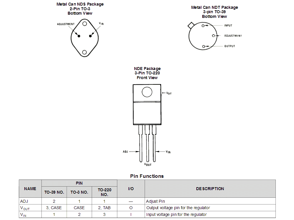
Image Courtesy: http://www.ti.com/lit/ds/symlink/lm117hv.pdf
LM317HV 0-60V Regulated Adjustable Variable Power Supply The Design
The next diagram shows the standard LM317HV 0-60V variable regulated power supply circuit, in fact this configuration may be universally applicable to all LM317/LM117, LM338, and LM396 IC family.
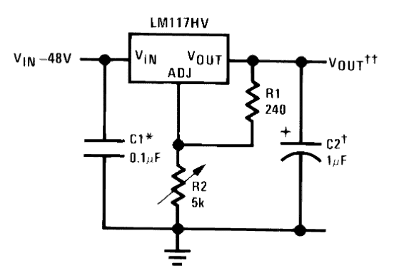
Referring to the design taken from its datasheet we can see that the variable resistor or the potentiometer is specified as a 5K pot, but actually this should be much higher than this value, may be around 22K for achieving a complete 0 to max adjustable output.
The input shows a 48V but we can go a bit higher than this and use upto 56V DC as the input, but please do not stretch it to full 60V as that would mean operating the device at the verge of its breakdown limit and this could make the IC vulnerable to damage.
In case you operate it with a 60V input or slightly above this, then short circuiting the output terminals accidentally could cause an instant damage to the IC, that's why it is not recommended to force the IC to work at its full throttle.
Below this limit, the internal short circuit protection feature could be expected to work normally and safeguard the IC from any possible short circuiting at the output.
C1 may be included only if the shown circuit stage is over 6 inches away from the bridge rectifier and the associated filter capacitor network
C2 is optional and may be included only to improve performance which would help eliminating all possible spikes or transients in the DC line.
For achieving a fixed regulated voltage, R2 could be replaced with a fixed resistor with respect to R1, this may be calculated using the following formula:
Vout = 1.25(1 + R2/R1),
where 1.25 is the fixed reference voltage value generated by the ICs internal circuitry.
You can also use the following software for calculating the same:
Adding Protection Diodes and Bypass Capacitor
The next diagram shows how a couple of diodes may be added to the basic voltage regulator design for reinforcing the circuit with extra protection, although this may not be too crucial.
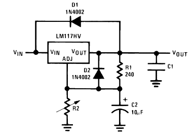
Here D1 protects the IC from the discharge of C1 due to an accidental short circuit of Vin with the ground line, while D2 does the same against C2 discharge.
The role of C1 is already explained in the previous paragraph, C2 is used as a bypass capacitor. C2 may be included to further improve the output DC regulation as it would help to eliminate all sorts of ripple voltages that might appear across the output.
Adding a Simple Current Limiter Stage
Although the LM317HV is internally restricted to produce not more than 1.5 amps at the output, in case the output current is required to be strictly below this limit or any other desired limit below 1.5 amp, then this feature could be achieved by adding a straightforward BC547 stage as shown below:
The diagram also shows the complete LM317HV high voltage 0-60V variable regulated power supply circuit in a pictorial format.
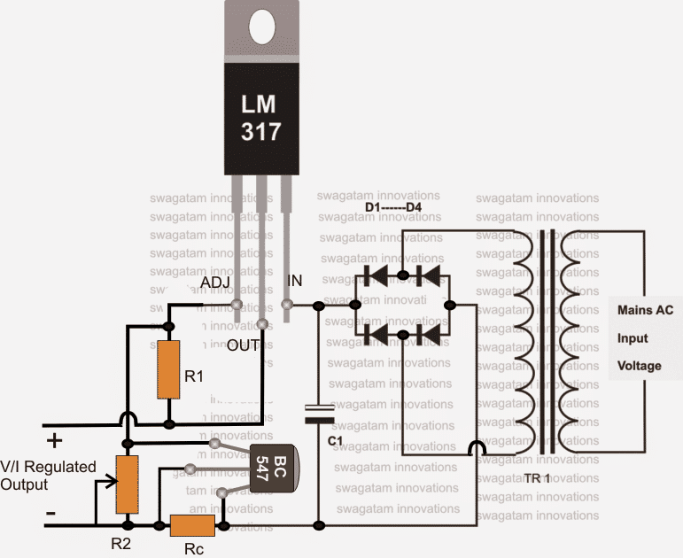
Here R1 refers to 240 ohm, R2 could be a 22k pot, and Rc may be calculated using the following formula for achieving the required current control feature:
Rc = 0.6/Max current limit value.
For example if the maximum value is selected to be 1 amp, then the above formula could be calculated as:
Rc = 0.6/1 = 0.6 ohms
the wattage of the resistor could be calculated as given under:
0.6 x 1= 0.6 watts
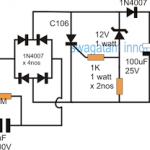
The diode in the bridge rectifier should be preferably 1N5408 diodes for ensuring a smooth rectification with no heating issues.
C1 may be anything above 2200uF/100V, although lower values will also do for lower current loads and for non critical loads which do not mind slight ripple factor in the line.
The transformer could be a 0 - 42V/220V/2amp.
The 0 - 42V is recommended because after rectification and smoothing this final DC could exceed a little over 55V.
The next article we might possibly discuss regarding the various application circuits using the LM317HV high voltage regulator IC.
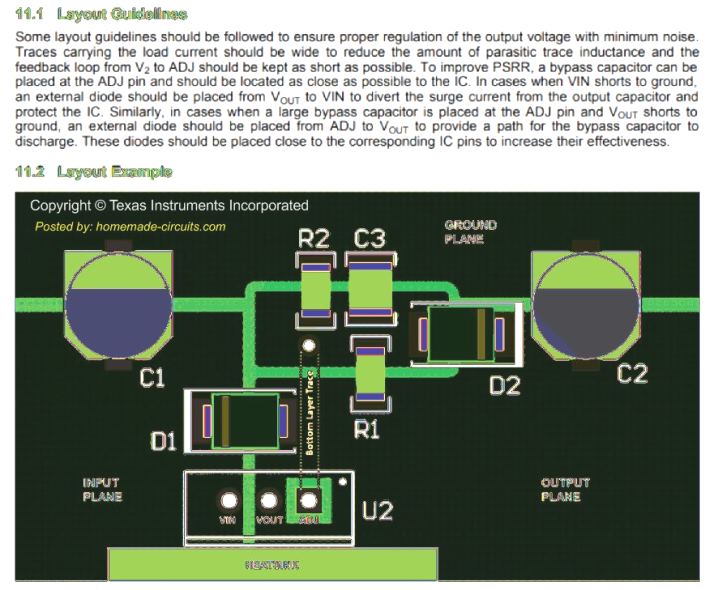
PCB Layout (with reference to the second diagram)


Questions & Answers
Hi sir, i have 38-0-38 transformer,can i use this transformer on this circuit?
Hi Elmar,
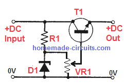
It is a touch and go situation, because your transformer voltage after rectification could be as high as 56V….Although it may be fine for this circuit, it is on the borderline…You can use an emitter follower regulator at the input of the above circuit to ensure that the regulated input to the IC never exceeds 56V…
Thank you sir, can you give me the value of those components sir.
Sure, I can give it to you!
Transistor can be TIP122
Zener diode can be 56V 1 watt.
R1 can be around 4.7k 2 watt
VR1 is not required. You can connect the base of the transistor directly between the zener cathode and the R1.
Thank you very much sir……
Wanna make a diy 0-60v 0-20 amp power supply using 3055 transistor and lm317
Kindly help for a nice accurate and powerful circuit
You can try the second last circuit from the following article:
https://www.homemade-circuits.com/lm317-with-outboard-current-boost/
Dear Mr. Swagatam
I need 53 V input and 12 -15 V output for a 2 lights and webasto diesel heater ( 5 -7 A)
I would like to make circuit as you give us on March 27, 2022
I have 6 nos TIP 2N3055
do i need to make 3 X parallel LM317HV?
If need, how to add 3 x lm317HV in parallel. Just put in parallel with no resistors between
Input is from lifepo4 batteries 48 -53 volts do i need capacitor at the input?
R1 is 240 OHM , how many W
R2 could be a 22k pot.- how many W
Thank you very very much for your help.
Regards, MATJAZ
Hi Matjaz,
If you are using 2N3055 transistors then adding 317 in parallel is not required. For 7 amp current only 3nos of 2N3055 are enough.
If you want to connect 317 in parallel, first build a single 317 circuit with resistor and pot, then add two more 317 in parallel to the first one.
Make sure to install all the 3 ICs on a single common heatsink.
Capacitor will not be needed at the input.
240 is 1/4 watt
pot can any ordinary pot.
Hello,
I would like to try your power circuit for a project I am working on, but would like to ask a few questions before I attempt to build the circuit. The input voltage will be input 110/120VAC and I am looking for a variable output of 12VDC – 20VDC 4a-8a. Can you recommend correct components for this?
Hi, to implement this circuit you will need a 120V to 20 V transformer. After this you can rectify the 20V AC from the transformer and use it as the input DC for the above explained LM317 circuit.
For increasing current you can modify the basic circuit into the following design:
Hello sir, I check the circuit but the seller gave me wrong ic instead of lm317, but I got 5.62 at the output. So what could be the actual problem or can it be the tiny wire I used for the circuit.all my connection are correct. My Rc should be 0.6ohm and is not found in my place so I used two 1ohms 1 watts in parallel and 0.22 ohm’s in series with the resistor
as you instructed becausee 0.1 ohm’s is not found, C1= 6800uf 25v, R2=22kpot, R1=240 ohm’s.
Hello Youngking, that seems strange.
With a 22K pot and 240 ohm resistor the output could be varied from 1.25V to 30V. Something is not right in your circuit. I suspect the IC itself may be faulty.
Instead of 317 you can try a fully transistorized circuit as explained in the following post, which will give you the same results as LM317.
How to Design a Bench Power Supply Circuit
Good morning sir , sir I built this 0- 60 variable power supply the one using lm317 and bc547, but my output is 0.15 when turn my multi meter to left hand side written 200. But if I still turn it down to 20 my output will be 2.18. my transformer is 12-0-12v, what will be the problem no components is heating up or may be you didn’t indicate the Bc547 pins because the facing is confusing I also attached pictures on the values I get with the multi meter.
Hello Youngking, this is one of the simplest designs and cannot go wrong. A problem can arise only if there’s a fault in the connection or the IC itself is faulty. The BC547 pins are clearly indicated in the pictorial diagram, the emitter pin is shown connected with the ground.
You can try making the basic design first, and check the response, if still it doesn’t work then either your connections are not correct or the IC itself is faulty.:
Dear sir,
Please sir, I intend to get 1.5A output from the circuit by removing the Bc 547 stage.
1. What else do I have to do or modify to get the 1.5A output?
2. Can I add filter capacitor at the regulated output?
3. Is the heat dissipation of the lm317 directly proportional to the difference between the input Voltage and output voltage like in the case of 2n3055 in one of your variable power supply circuits you told me about?
Thank you for your help, sir
Hi Godfrey,
Getting 1.5 amp from LM317 can make it very hot. You can simply replace it with an LM338 for getting 1.5 amps easily.
1) Just replace LM317 with LM338, or use two LM317 in parallel and mount them over a single common heatsink
2) You can add a capacitor at the output
3) Yes, since LM317 is also a linear regulator the heat dissipation will be directly proportional to the difference in the input/output voltages.
Dear sir,
Please sir, how can the circuit be modified to have two outputs 12V and 5V at 1.5A?
Hi Godfrey,
you can adjust the pot to get 12V output, and then use a 7805 IC to convert the 12V to 5V. However you cannot get 1.5 V simultaneously from the two outputs. For this you may have to replace the LM317 with a LM338.
Okey sir, thanks alot. I appreaciate.
You are welcome!
I wanted to build a variable power supply but unfortunately I don’t have the voltage regulator lm317hv.
I need 60v 20a output.
So what should I use instead of lm317hv?
For 60v
LM317HV isn’t available in this place where I live. So can you provide an alternative of this please
There’s no other easy alternative for LM317HV
You can try the following concept:
Variable Voltage, Current Power Supply Circuit Using Transistor 2N3055
Okey sir, thank you for your responses, but the 1 ohm’s will it be 1 watts.
Yes you can use 1 watt
Good day sir, I hope you are doing well. My questions is concerning the 0-60v variable power supply that uses lm317H v (1) so if I use transformer of 14v/220 v/amps unknown won’t I get reasonable output of about 30v. (2)- the calculation of getting the RC, let say I go with your calculation which say’s 0.6/1=0.6 ohm’s for the resistor then the wattage is 0.6×1=0.6watt. I know 0.6 ohm’s is not found in my area so any substitution for such ohm’s. Thanks so far for your effort
Hi Youngking, if you are using a 14V transformer, then the output after rectification and filtration will be 14 x 1.41 = 19.74V
Yes RC will be 0.6 Ohms for a cut off current of 1 amp. Wattage calculation is also correct.
To build the 0.6 ohms you can use two 1 ohms in parallel and then add a 0.1 ohm in series, or you can try some other similar combination.
Dear Swagatam:
Greetings.
My LiFePO4 battery pack is being designed for 72 volts (nominal) with 23 cells in series and 58 cells in parallel amounting to 25kwH. I will be needing a charger at 230v AC input, and can take care of the demand for 78v at 100 amps. I am unsure if such a circuit can be built as a single unit. Can you help with a circuit, where I can put two or three modules in parallel with each of them at 78v, to arrive at the desired current rating? Thanks in advance.
Dear Madhav, a charger circuit with auto cut off can be built but you will require a transformer which can convert the 230V into 78V 100 amps for the batteries
Hi Swagatam;
I have test for LM317; input is 23 V output is 12 V load is 0.32 A. LM317 is overheating. My I have your opinion. Thank and regards
Hi Suat, yes if the input/output voltage difference is high then any linear regulator will heat up, you can do nothing about it except connect a large heatsink, or do fan cooling. A capacitive current dropper is the best method which can be connected to 23V AC and then rectified for the motor and meter.
Okey Sir,
then since my source transformer output is 23 AC and it is necessary to place capacitor after the rectifier and then DC output is 33 DC. That is over burden to LM317 or even 7812. As far as I understand your evaluation, I should either change my transformer or lower the AC input source to about 15 V. So I should search the second choice first. Kind Regards
Hi Suat, yes using a 12V transformer will quickly solve the heating issue.
Hi Swagatam;
by considering above statement; “C1 above or min. 2200 mF”, let’s use 2200 or 6800 mF then in the aspect of output dc voltage, result would be same or 6800 is would be more effective? Regards
Hi Suat, the higher the value of C1 the better will be the filtration. 2200uF is a reasonable value, but higher values can be tried for improving the output DC further.
Hi Again Swagatam;
Sorry just to completely understand the matter let me ask; for instant I have transformer input 220 and output 24 V and 100 VA. (I think app. 4 Amps) When I use 2200 mf capacitor as a filter after diodes I measure about 34 V output. In case I would have used 3300 mF then the gain would be more output voltage or more stable voltage? and also please comment what about the output current would be the same, less or higher?-thanks and kind regards
Hi Suat, the gain will be more stable voltage at higher loads. Max current will remain 4 amps only, but higher capacitor values will ensure that the output doesn’t drop with increasing loads upto 4 amps.
Hi Swagatam;
Thanks a lot the above info is highly precious for me. Then please advise if it is possible to place the capacitors as parallel to increase the capacity. For instance to use 2 of them as 2200 mF 35 V plus 3300 mF 63 V. Or capacitors voltage values should be the same too? Regards
Hi Suat, you can put the capacitors with different voltages in parallel, but the minimum voltage of a capacitor should be at least 1.5 times the DC output of the power supply. Higher voltage values than this will be OK, no issues.
Thanks Swagatam;
Power supply input 220 AC output is around 22 V DC but after bridge diode and capacitor that arises to 33 V DC. So, then I should consider 22 x 1.5= 33 V or 33 x 1.5= 50 V? For instance I have 35 V capacitor That will be any issue or tolerable? Regards
Hi Suat, a 35V capacitor can be too risky and might blow off if accidentally the DC across it exceeds above 35V. That is why, for better safety a 1.5 times more value is recommended. So a 50V capacitor is recommended for a 33V supply.
Please suggest me a circuit diagram of a 60v 30a (1800watt) variable power supply.
And also give a 1800 watt power supply diagram. Because I’m not able to find it nearby
You can try the following circuit:
https://www.homemade-circuits.com/lm317-variable-switch-mode-power-supply/
replace the Q1 transistor with three IRF9540 mosfets in parallel, mounted over a common heatsink
Also make sure to use very thick wires for the inductor L1.
First test the original low current version, if you succeed with it, only then go for the upgrade