I am presenting a circuit design here in response to a request sent by one of the avid readers of this blog. The proposed circuit is of a sequential LED light driver, especially designed to suit the application of a multipurpose car tail light indicator.
Circuit Connections
The circuit is integrated to the brake switch and works as a brake light, it’s also connected to the turn signal switches for indicating the turning of the vehicle with chasing light patterns, and the circuit can also be used just as an ordinary tail light warning indicator.
In order to successfully make the proposed car LED chasing tail light, brake light circuit, it will be important to first understand the circuit functioning in details with the following points:
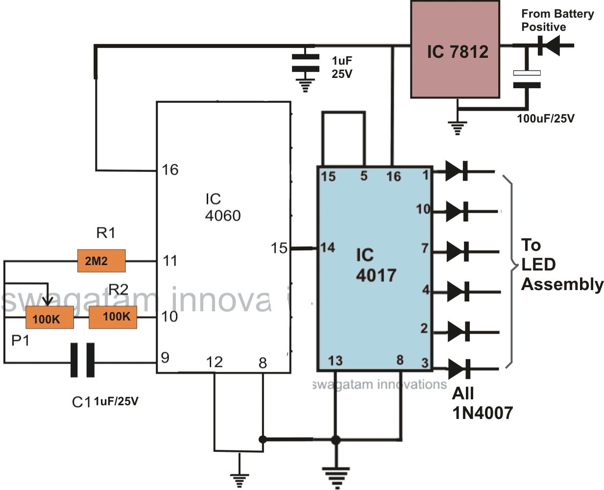
How it Works
The CIRCUIT DIAGRAM can be divided into two sections, the first consists of the LED driver stage, where the IC 4017 forms the main LED sequencer and is configured in its usual counter/divider mode.
Only six channels of the IC 4017 have been used to avoid lengthy sequencing patterns and crowding of the LEDs.
Two arrays of LED are taken from the above outputs such that they “run” in opposite directions when switched ON, however both the channels are never run together since they are used for the LEFT, RIGHT turn indicator purpose and therefore only the relevant side is switched ON depending upon the vehicles turning side.
The IC 4060 is configured in its standard mode, as an oscillator and is used for driving the IC 4017 with its clock signals.
With every rising peak of the clocks, the outputs of the IC 4017 shift from one pin out to the next in the shown order, making the connected LED illuminate sequentially.
The pot associated with the IC 4060 may be used for adjusting the sequencing speed as desired.
Left Right LED Sequence Layout
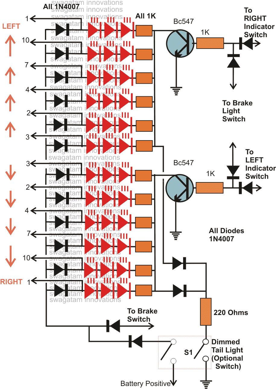
The LED stage consists of the LEDs arranged in a definite sequencing pattern as discussed in above explanation.
The LEDs are connected to the IC 4017 outputs so that they are able to perform the intended sequencing or chasing function.
The LEDs are also discretely wired up to the different vehicle controls like the brake switch, the turn signal switches and an optional DIM tail light switch.
When the brake switch is applied, the LEDs light up all together brightly, indicating the application of the brakes.
When one of the turn signal switches is switched ON, say for example the LEFT turn signal is applied, the LED array positioned on the LEFT portion starts sequencing from center, toward LEFT, indicating the intended moving direction of the vehicle.
The above function is repeated toward the RIGHT side by the right portion LED array when the right signaling is made with the relevant switch.
A couple of optional switches (S1) may also be included and wired up with the LEDs as shown in the diagram.
This provides a feature of operating the LEDs as a dim tail light indicator which stays switched all the time with a relatively lower brightness, however when the brakes are applied the LEDs light up brightly.
The driver circuit is powered through the IC 7812 which is a voltage regulator and provides safe operating stabilized voltage to the circuit, irrespective of the input fluctuations.
In the above position, the turn signals will also work, but is not recommended as the DIM light at the background may affect the signaling.
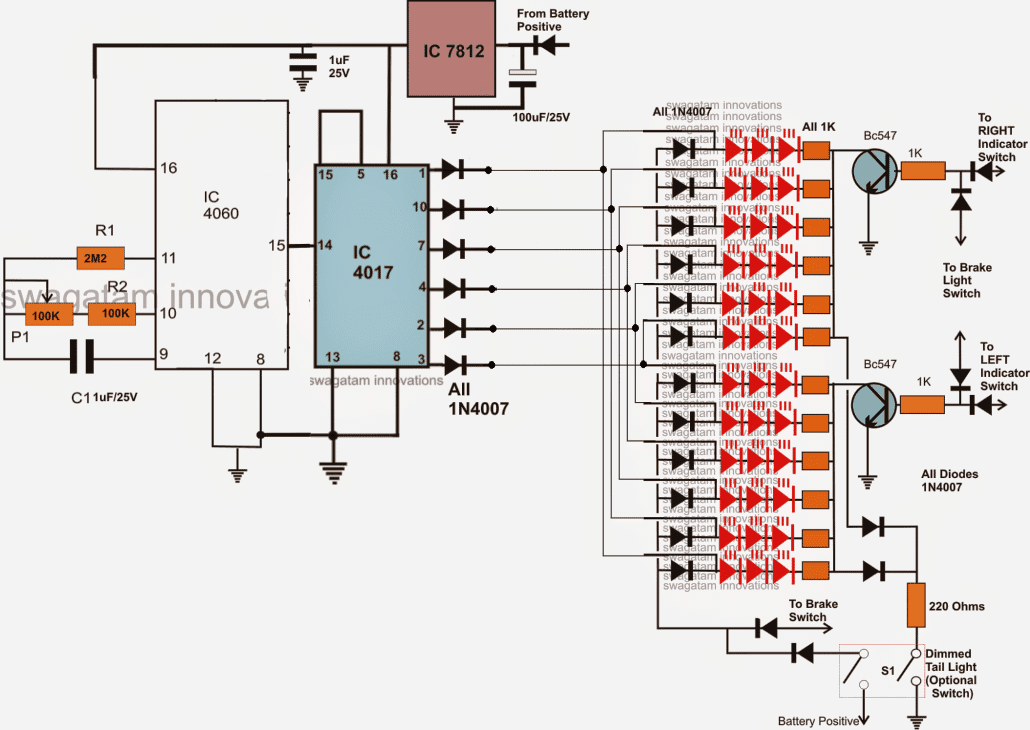
The following image shows the complete combined circuit design of the above discussed two stages:
Complete Schematic Diagram
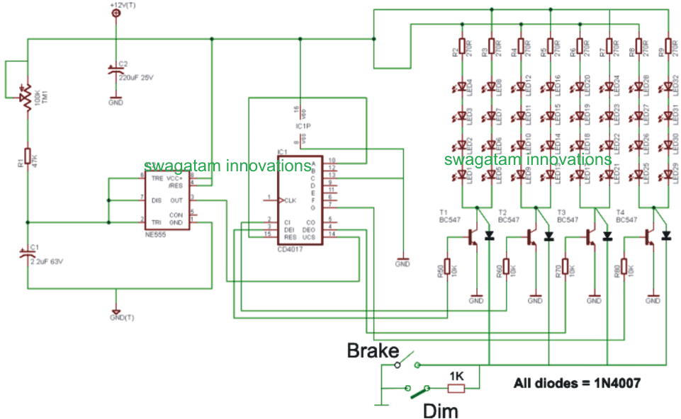
A simplified and scaled down version of the above explained car chasing light circuit with brake light and park light can be witnessed below:
The post illustrates an elaborate circuit design that can be used as an enhanced "chasing" LED tail light for cars and other vehicles, the design also includes the modification details for the associated turn signal and the park light systems. The idea was designed and presented by Mr. Jason.
The entire discussion may be referred to in the comment section of this post:
Sequential Turn Signal Indicator
Modified car chasing light circuit
The circuit description below explains the proposed modified car chasing light circuit, as presented by Mr. Jason:
Okay, I had a chance to work on it, but have not tested it on the breadboard yet. If this works, one 4017 and 555 timer chip can be used for both left and right turn signal.
The schematic
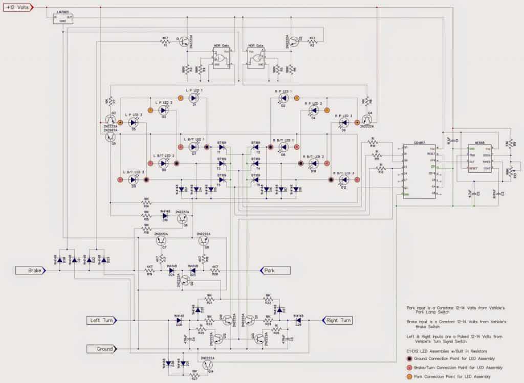
How the Circuit Functions
I hope you can understand what it is doing. The LED's I will be using have 3 wires out. One is ground, one is Brake/Turn, and one is Park. When just 12 volts is hooked up to the assemblies,
It seems that there are different resistors to control the brightness (a fixed amount) for the brake/turn, and for the Park. Which is a nice factory option from the LED assemblies themselves.
If I just use one wire (the brake/turn), and a potentiometer to adjust the brightness for the Park, I am thinking I would need a 19W potentiometer, and those are expensive.
Each LED assembly draws 246mA at 12.8 volts. If all 6 lights were on, that's 246mA * 12.8 volts = 18.89W of power. So, wiring them separately and using a common ground to switch them on and off, would eliminate the need for a potentiometer, since the resistors are built into the lights themselves.
I am using a NOR gate to turn off the Park LED's when the brake or turn signals are applied.
I am not sure on the resistor values. I've changed the Vcc for the 4017 and 555 to run off of the LM7805 voltage regulator.
By doing that, I have also run the other inputs/outputs of those chips off of the LM7805 as well? I am not sure of the Capacitor and Resistor values needed then.
I'd like to switch all power to 5volts for less power consumption. Except for the LED supply voltage of course. that needs to stay the 12-14 volts coming straight from the wiring of the Truck.
I took your suggestion and added the transistor and the resistor to rapid discharge the 470uF capacitors so the LED's do not continue to sequence for 15 seconds AFTER the turn signals have been turned off.
As per your request, I have connected them to the last sequencing output of the 4017. It makes sense, and as you said, should work for turning off the LED's from sequencing.
If I can get this to work, I plan on building a circuit to allow up to the 8 sequencing LED's (available outputs for the 4017 since two are used to reset the 4017 and the SCR's).
I will do it using either dip switches or more simply, solder bridges.
I will also make it so that solder bridges will be before and after a resistor of each LED, if a resistor is needed for standard LED's to be wired up.
I need to do this for my car, and my new lights will have 5 rows of LED's I will need to sequence instead of the 3 that my nephews truck has.
So I'll need to design the circuit to work for both. Fun Stuff!
Using High Watt LEDs
Now let's discusses how to construct a chasing car tail light circuit using high watt amber LEDs. The idea was requested by Mr. Brian Walton.
Technical Specifications
I've been giving the project some further thought. I am wondering what changes might be needed to use single, higher power leds instead of the advised 5mm ganged in threes? So there would be 6 LED's rather than 6*3 5mm
The reason is that I have combined LED DRL & indicators on the front of my car, so I would like to retain the OEM look & feel at the rear - where I propose to use your excellent circuit design.
I'm thinking along the lines of the LEDS in the link below.
They are Osram Opto Diamond DRAGON Series GW Amber LED. They are designed for automotive use in DRL's and indicators.
They are 2.9v forward voltage and appear to take about 1.4A at typical lumens.
The LEDs above are not definitive but a suggestion in terms of output and style for my construction needs.
So my question is can the circuit take or how do I need to modify the circuit to take the extra power these LED's may take.
For info; from a practicalities point of view, I intend to have a separate driver circuit for each side of the vehicle - it makes installation simpler given i'm going to attach the pulse form the existing indicator
relay as discussed previously with you.
I hope you can advise me (again!) and many thanks for your devotion to the electronics hobbyist on the web.
Best wishes
Brian
Solving the Circuit Query
Thanks Brian!
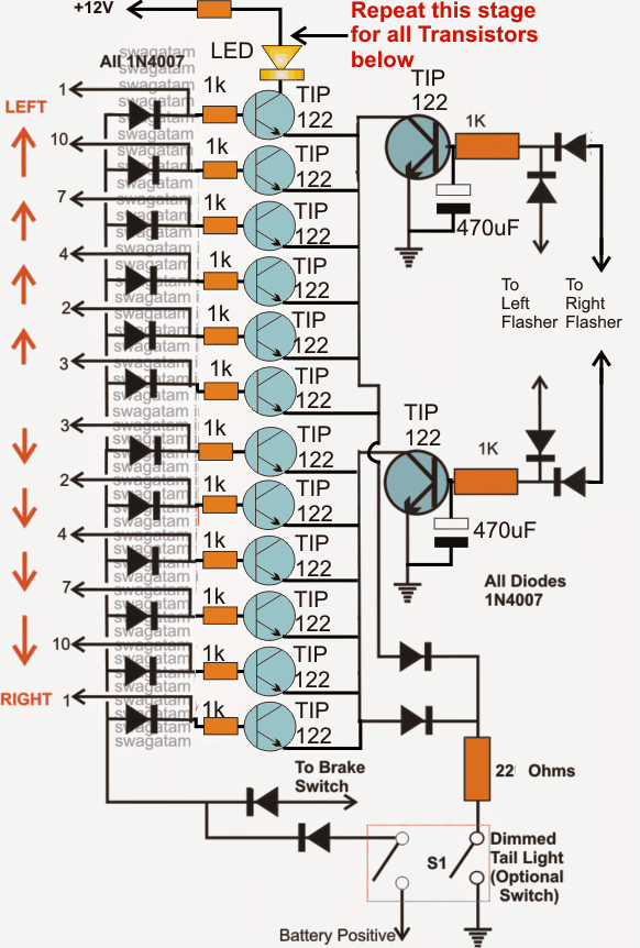
Incorporating higher wattage LEDs will need individual transistor buffers across the 6 outputs from the IC, it's actually very easy to implement.
I'll try to explain the connections verbally, although I am also thinking of updating a suitable diagram for this particular application, I may do it within a couple of days....in the meantime you could try doing the following mods in the above circuit:
Use TIP122 for the buffer transistors.
Connect the bases of the 6 transistors to the respective outputs of the IC 4017 via the indicated diodes. Make sure the base have individual series 1k resistors
The LEDs will need to be attached across the transistor collectors and the positive, the LEDs too must have their own series limiting resistor
The LED resistors could be calculated using the following formula:
R = (Us - LEDfwd)/I
where Us is the supply voltage,
LEDfwd is the optimum glow voltage of the LED or the forward voltage drop spec.
I is the optimum current for the LED as specified in its datasheet.
That's all..... now your circuit is ready and would be capable of handling any type of high watt LEd in the range....
Circuit Diagram



Questions & Answers
Great write up! I'm going to do this within the next couple of weekends.
2 questions…
Do both sides need separate drivers, or is it one driver to run both sides?
Also, looking at the LED portion of the circuit we'll take the left side for example, I'm confused as to why the right turn signal power is connected to the left turn signal.
Thank you
Thanks Chris,
You won't require two drivers, the first circuit works for both the sides.
The arrow heads from the LEDs which are assigned with identical numbers will need to be joined together and connected to the relevant diode termination from the IC4017.
yes you are right, it looks like a drawing mistake, please ignore it, the right/left power must obviously join with the corresponding sections:)
Swagatam,
I have read this thread and some of the links. I understand what I want to do is entirely possible but I need some clarification and/or a specific diagram for my challenge.
I would like the sequential turn signals like Toontje and Chris requested with the turn signals priority over the brake signal AND functioning (dimmer) tail lights when stop or turn signals are NOT in use.
A link to a corrected, specific diagram would be fine.
THANX!
Also I want to use 10 outputs with 3 LEDs on each x2 for each side.
(30 LEDs + 30LEDs for left and 30LEDs + 30LEDs on the right)
Hello Bill,
Please check out the first circuit given in this article. It should suit your application.
Since you are interested to use all the 10 outputs, T1 disappears from the circuit and all the 10 outputs of the 4017 IC get configured with the SCR/LED network as shown.
For each three LED string you will need a 150 ohms series resistor for limiting current.
https://www.homemade-circuits.com/2013/03/sequential-bar-graph-turn-light.html
Hi , i wanna use this for turn lights
1 this circuit is secvential , first led is on until last in on , or only one at 1 time ,
2 you sad in one comment that max 3 led / 1out , connected in paralel?
3 what happen if i conect from the flasher unit Taillight
1) it's sequential but one led at a time, not like a bar graph, rather it's like a dot sequence.
2)yes three LEDs in series for 12V supply, a couple of more can be added with 16V supply.
3) sorry, did not get your question??
Hi Swagatam
How could i use this circuit using a feed direct from the flasher unit? I was wondering if it could be modified in the same manner as the sequential bar graph circuit that has the time delay circuit addition to hold the current.
I want to use the above for the rear indicators only and obviously the feed from the flasher is readily available – Rather than having to run a specific signal wires from the front of the vehicle to the rear just to supply the signals.
Thanks in advance of any assistance
Brian
Hi Brian,
you can achieve the same by doing the following quick modifications.
Increase the base resistor values of the BC547 transistors to around 10K, and connect a 470uF/25V capacitor between the resistor's outer ends (diode junctions) and ground.
Do this for both rthe BC547 transistors.
finally you may simply integrate the Right/left diode ends to the readily available outputs from the flasher circuit over the relevant turn signal lamp sockets.
Hi Swagatam
Many thanks for the swift reply to an old thread!
I will follow up on your suggestion and maybe others will find the mod useful too!
You've got a fantastic site here for the hobbyist and done some great work and provided a fabulous service for the less able
Thanks again
Brian
Thank you Brian! The pleasure is all mine!
Hi (again) Swagatam 🙂
I've been giving the project some further thought. I am wondering what changes might be needed to use single, higher power leds instead of the advised 5mm ganged in threes? So there would be 6 LED's rather than 6*3 5mm
The reason is that I have combined LED DRL & indicators on the front of my car, so I would like to retain the OEM look & feel at the rear – where I propose to use your excellent circuit design.
I'm thinking along the lines of the LEDS in the link below.
They are Osram Opto Diamond DRAGON Series GW Amber LED. They are designed for automotive use in DRL's and indicators.
They are 2.9v forward voltage and appear to take about 1.4A at typical lumens.
uk.rs-online.com/web/p/visible-leds/7173805/
The LEDs above are not definitive but a suggestion in terms of output and style for my construction needs.
So my question is can the circuit take or how do I need to modify the circuit to take the extra power these LED's may take.
For info; from a practicalities point of view, I intend to have a separate driver circuit for each side of the vehicle – it makes installation simpler given i'm going to attach the pulse form the existing indicator relay as discussed previously with you.
I hope you can advise me (again!) and many thanks for your devotion to the electronics hobbyist on the web.
Best wishes
Brian
Thanks Brian, I appreciate your interest very much:-)
Incorporating higher wattage LEDs will need individual transistor buffers across the 6 outputs from the IC, it's actually very easy to implement.
I'll try to explain the connections verbally, although I am also thinking of updating a suitable diagram for this particular application, I may do it within a couple of days….in the meantime you could try doing the following mods in the above circuit:
Use TIP122 for the buffer transistors.
Connect the bases of the 6 transistors to the respective outputs of the IC 4017 via the indicated diodes. Make sure the base have individual series 1k resistors
The LEDs will need to be attached across the transistor collectors and the positive, the LEDs too must have their own series limiting resistor
The LED resistors could be calculated using the following formula:
R = (Us – LEDfwd)/I
where Us is the supply voltage,
LEDfwd is the optimum glow voltage of the LED or the forward voltage drop spec.
I is the optimum current for the LED as specified in its datasheet.
That's all….. now your circuit is ready and would be capable of handling any type of high watt LEd in the range….
Best Regards.
Hi Swagatam
I really appreciate your assistance and the fast replies are a treat too!
I have seen your piece about limiting resistors on another page and thanks for reiterating it.
I really pleased I've given you some food for thought in enhancing your original design!!
Im looking forward to seeing the revised diagram ….if and when you have the time that is! I'm on a steep learning curve and think I get your explanation but the proof will be a bonus.
Regards
Brian
Thank you Brian,
I'll draw the schematic and try to post it soon in a new article, for your reference.
Thankyou again Swagatam!
As a child I used to pull apart old radios to see how they worked. That was a long time ago ( hint pre transistor) Since then I've always been fascinated by the world of PC's and now, with your site, I've had my interest in electronics reignited!
You are right Brian, I too started in the same manner, and I think most of the hobbyists usually begin by breaking and mending old junks.
Be assured with my association your electronics passion will not just ignite but light up fiercely:)
I have prototyped this circuit on a breadboard and the issue I am having is when I make the connection on the transistor (brake light circuit) I get a single row (3 leds) lit… but no sequencing. But if I touch with my finger on the resister lead coming from pin 11 on the 4060 ic, I get the lights to sequence at a fast rate. (and unable to adjust the speed with the pot). What could be my issue?
Making the brake connection is not supposed to produce the sequencing effect, rather it's supposed to produce a constant illumination on the LEDs.
Switching ON the turn signal connection will produce the sequencing effect.
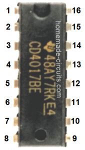
..connect an LED from pin16 to ground via 1K resistor of IC 4060, this LED should blink in order to confirm the correct working of the IC 4060, if this does not happen would indicate a malfunctioning IC 4060 stage.
correction: connect the LED from pin15 of IC 4060 to ground via 1k resistor and not from pin 16….
Thanks, I meant turn signal circuit. I found that changing the cap from pin 9 of the 4060 ic from 1 uf to .1 uf fixed the problem. I also eliminated the pot and with selecting the correct resistor, I got the sequence to go at the speed I desired.
I also have the brake light function working perfectly. The only thing I noticed is that there is a slight voltage leakage Bc547 transistors. (in a dark room I can see the faint sequencing/lighting of the leds.)
OK that's great, however 1uF would also work for producing the same results if P1 is adjusted properly, the leakage could be probably stopped by putting a low value capacitor across base and ground of the BC547 transistors.
not sure if my comments came through, but this is exactly what we are looking for to make for my son's 73 Mach 1 Mustang. we'll post as we build. thank you for all your help to others – i have learned a lot by reading all the follow up comments.
thank you stuart, you are most welcome!
Hello,
I am new to doing anything like this, first of all. I did bread board this out also. I am not using switches yet just the positive and negative ports of the bread board with jumper wires. When I have the wire from the 220 Ohm resistor to negative the lights sequence, I had not plugged the right blinker switch wire to the positive side yet either. Am I shorting out somewhere? Also when I do plug the wire into positive on the breadboard and then the wire for brakes it does go solid. Is the To brake switch for the running lights and the to brake light switch run them brighter as in when applying the brakes? Getting closer to getting it running just have a few things to sort out possibly. I am working on this to tinker, but also want to incorporate something like this on my 1966 Mustang. I know there are kits for sale, but whats the fun if you cant try it yourself. 🙂 Kind of like the setup from vintageleds.com website.
Thank you and have been reading through all questions and comments as well
Hi, the 220 ohm switch is ganged with the another switch indicated just beside…so both these switches need to be switched ON simultaneously for switching ON all the LEDs together (dimmed) and with the sequencing effect cancelled.
In order to implement the brake light illumination the vertical diodes connected at the bases of the BC547 transistor also need to be connected the positive line simultaneously along with the bottom diode end indicated as "to brake switch", I think you might have missed it…
Yes, I did miss that. Thank you very much for your help.
you are welcome!
Good morning sir,
I have done with this ckt last night. Just a prob. there…Am I need two diodes;one for ic out put and another with led pannel. Please help…..
With regards ,
K. Kausik
Kaushik, yes that's right, it is clearly shown in the diagram, the LED panel diodes go to the brake light switch while the arrow heads show the points which needs to be connected with the 4060 diodes.
Not sure what is going on, but when I use the 1uF/25v at C1 on the IC4060 nothing happens. When I use a 103 capacitor all works fine. Any suggestions as to what is going on? I am a novice at this and I thank you for your reply.
that's very strange….by saying "nothing happens" do you mean to say that the LEDs don't "run"??
under any case that cannot happen, because changing the 100k pot setting should adjust things as per the C1 value and help to achieve the intended response across the LEDs ….please check all the pinout connections of the IC with the relevant components.
The LED's will at times come on and stay on, at other times will not come on at all.
No sequencing at all. Even when connecting an LED to pin 15 as you had suggested in an earlier post, the LED does not flash stays solid. Is there a certain way I need to connect the 100k pot? I have it all laid out on a breadboard, the pot has three pinouts with a small setscrew on top to adjust. I have connected it various ways and there is nothing happening when I do any adjustments to the 100k pot. Yes, I will double check all connections as well. Thank you Swagatam.
that's quiet strange and should not happen, because both the ICs are very reliable with their functioning and will start working immediately, if wired correctly.
the pot should be as shown in the following image:
any of the outer terminal can be eliminated, while the remaining two employed across the indicated points of the circuit.
Alright, I'm most definitely determined to make this and apply it to my car, BUT im having trouble with the schematics. Can you please, for me and everyone else wanting to make this, make a new schematic that incorporates them both together. In the first schematic where can you apply a POT? im assuming PIN 11 of the IC4060. Also are the diodes(1n4007) running from 4017 in the first schematic the same ones appearing in the 2nd schematic that connect to the LED's? If the 1st schematic is the only driving circuit how is there a left and right side of LED's in your 2nd schematic?
I would really appreciate if you could make another digram/circuit/schematic all in one with just a tad more detail, PLEASE you would be a hero.
I have the updated the design as per your request.
P1 is speed timing pot.
The left and the right turn signal switches decide which set LEDs need to "run" as per the user preference.
Thankyou so so much! Very helpful to see the updated circuit, cleared up what I was getting confused about. Time to order the parts and test it out.
you are most welcome:)
So I recieved all my parts and built this circuit on a breadboard…before finalizing this circuit on pcb board, how do I test this circuit without hooking this up to my cars positive+ground and brake switch? I don't want to go splicing wires in my car unless I know this is a fully functional circuit. I'm assuming I would have to hook this up to a power supply(12v)….but what could I use to imitate a brake switch signal and both left & right signal? Also to help others and myself, understand your diagram better; are those LED'S in series or parallel?
obviously you will need a 12V power supply to test the circuit on your work bench.
connect the 12v supply to the circuit, then make all the indicated "brake switch" wire ends common (join them together) and manually connect the joint to the positive line…this will simulate the brake application and hopefully illuminate all the LEDs (if you have done everything correctly.)
Do the same with the L/R wire ends…connect these individually to the positive line for implementing the relevant L/R chasing LED effect.
LED are in series on each channel
Sir, can you explain a bit on S1 switch, Battery Positive & Dim Tail Light. where do you install this switch inside the car. Is it necessary to have this switch. Thank you for reply.
Reeko, S1 is optional and may be included only if you want the dimmed LED feature.
S1 switches are GANGED together, that is both are joined and are switched ON in a combined way.
Please click on the diagram to enlarge and just wire the parameters exactly as shown.
Sir I have tested this circuit on a bread board, the BC547 blow up, I tested 3 times…what do you think could be the cause? I have check every wiring. The 7812 Vin and Vout, Vin is from the diode to +12V correct?
Reeko, the BC547 transistors can blow up due to any of the following four reasons:
base 1K not included.
collector shorted to the positive line
pins wrongly connected
duplicate quality B547 used
yes 7812 left pin will go to the input (+) source
as commented by Wade McBeth the leds becomes solid without sequencing and there is no blinking signal at pin 15 of IC 4060 , only in pin 7 the led blinks and rest pins show steady led, the touching of PIN 11 of IC 4060 signifies something as pin 7 outputs blinking led when touching pin 11. please clarify the point
the blinking rate or the osculations across the output pins will be different and will change as P1 is adjusted. Pin#3 will have the slowest blinking rate and pin#7 will have the highest blinking speed…this will be relative to the P1 adjustment.
For more info, you can go through the following link
https://www.homemade-circuits.com/2011/12/how-to-understand-ic-4060-pin-outs.html
as per as diagram one end of 100k resistor connected to pin 10 of ic4060 should be connected to one outer end of pot and the other outer end of pot should be connected to the another end of 2.2M resistor connected to pin 11 where the middle point of potentio meter also gets connected . Is it correct ? or one outer end of potentio-meter can be eliminated and only the middle point should be connected to another end of 2.2M resistor along with other pin of capacitor connected to PIN 9?
please refer to this image webnxt-india.com/swagatam.jpg
and correct me whichever should work,image 1 with RED circle and image 2 with green circle.
The middle is the most important pin of the pot, it must shorted with any of the outer pins, that will do the job.
to be precise only the middle and any one of the outer leads needs to be used, the other outer can be left unused….just as indicated in your no.2 diagram.
both the diagrams are correct.
thanks for support. whats the wrong with this circuit ?? please check image
webnxt-india.com/c.jpg
pin 9 10 11 of 4060 contains the exact resistors and capacitor (as 1uf didnt work i have tried 0.1 and .01 ) pin 8 and 12 ground and pin 16 Vcc .. so that PIN 15 should get blink signal.
i could not make it to work even after trying 3 ICs with all different components , i am 100% sure all components are working and wiring as per as your circuit . as this IC is very reliable what can be the cause ?? the 4017 part is working.