In this article I have explained a car power window controller circuit using a single push button or a couple of push buttons. The idea was requested by Mr. Win.
Technical Specifications
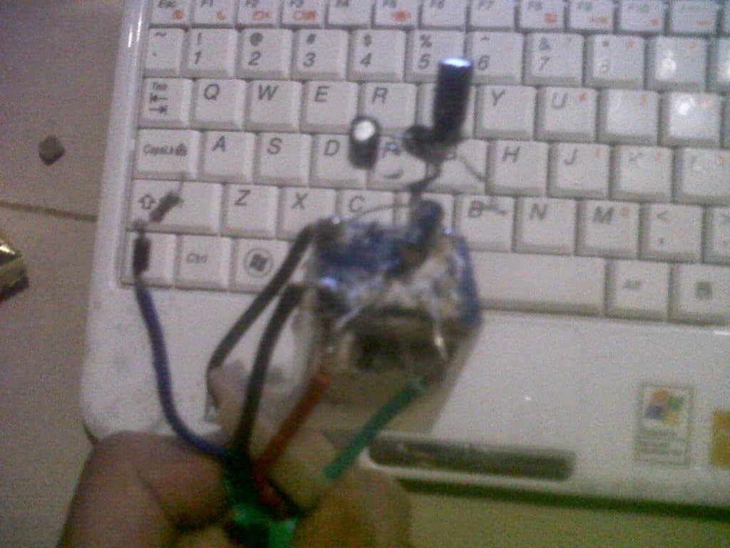
I'm winantiyo from Indonesia, i've read your post in your blog and i'm very like it.i have 2 project: 1. auto roll up power window for car 2. auto lock trigger by foot brake for carcan u help me for the circuit n schematic?auto up power window: i want my car window can roll up or roll down automatically with single click on power windows button switch..i ever see the auto roll up module with one relay 8pin, 2 transistor n 4 electrolytic capasitors but it has been broken, 1 resistor n 2 diode. but the series of part has been lost. there are 5 cables: +12V, ground, 1 cable to motor window, 1 cable to switch power window, and 1 cable again to another motor windows cable..here is the pic:
AUTO LOCK BY FOOT BRAKE:
i want to make my car door can locked automatically when all the door closed, key turn ON and i press my foot brake (+trigger). then the door can automatically unlocked when i turn off the key. i hope u understand my explanation...i'm sorry for my english..thank you very much.
The Design
Window Glass Up/Down Controller using a Single switch
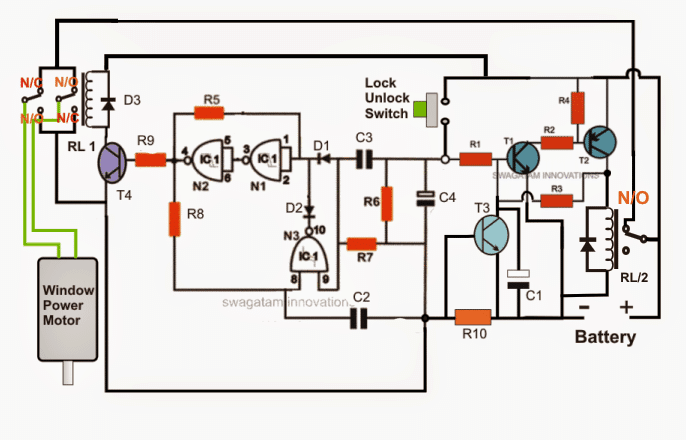
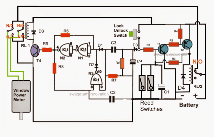
The shown car power window controller circuit basically consists of three stages: a transistor latch which includes a current sensor, a NAND gate based flip flop stage and a relay driver stage for flipping the motor actions alternately.
The indicated lock/unlock switch toggles the flip flop stage made by engaging three NAND gates from the IC 4093, whose output responds with a permanent high and low alternately with every push of the switch.
Parts list
R1, R3, R6, R7 = 100K
R5,R8 = 2M2
R9 = 4K7
C1,C4 = 22uF/25V
C2,C3 = 0.22uF
T1,T3 = BC547
T4= 8050
T2 =8550
RL1,RL2 = 12V/20AMP
ALL DIODES = 1N4007
R10 = TO BE CALCULATED
N1---N3 = IC 4093
This switch also makes sure that the latch section comprising T1 and T2 gets activated in order to allow the supply voltage to reach the remaining part of the circuit.
The output from the flip flop acquired at N2 pin4 is fed to a relay driver stage for activating the power window motor with a forward or a reverse motion depending upon the position of the window glass.
It must be ensured that while connecting the motor the polarity of the wires are set such that a high at pin4 of N2 actuates the window in the closing mode, and vice versa.
The relay is a heavy duty DPDT relay whose N/C, N/O contact connections with the motor enable the motor to carry out the desired to and fro movement.
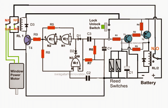
Normally, reed switches are employed for detecting the completion of the glass up and down movements in order to avoid the motor from getting loaded and destroyed, however here we have a taken a different and a much advanced approach.
In the proposed car power window controller circuit we have employed a current sensor stage in the form of T3, which detects a mounting current across R10 and switches ON itself when the level crosses a set threshold. When T3 switches ON it breaks the T1/T2 latch disconnecting the supply to the motor.
However if a reed switch is incorporated for the above actions, the reed contacts positioned for detecting the up and the down thresholds of the glass may be wired across C1, and T3 stage may be removed entirely. R10 may be replaced with a wire link (see figure below).
Using two switches
The above design could be much simplified if two separate push buttons are employed for the up/down operations of the window glass. The simplified power window circuit which incorporates just a few number of BJTs can be witnessed below.
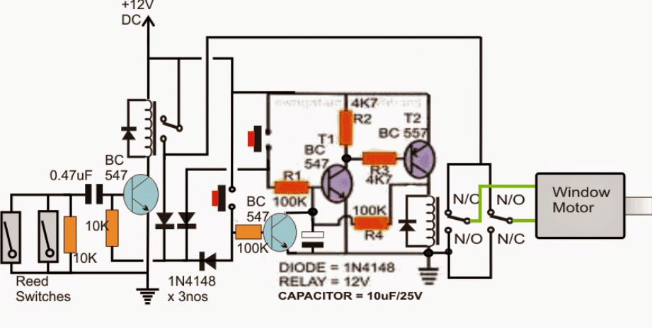
Four of the above circuits will need to be installed on each door of the vehicle for the required power window switching.
Upgrading the Car Power Window
In the above sections I have explained the circuit design of an automatic car power window controller, here we'll learn how it may be enhanced with more features.
The main circuit using a single button, posted in the previous article can be witnessed below for reference purpose.
Parts list
R1, R3, R6, R7 = 100K
R5,R8 = 2M2
R9 = 4K7
C1,C4 = 22uF/25V
C2,C3 = 0.22uF
T1= BC547
T4= 8050
T2 =8550
RL1,RL2 = 12V/20AMP
ALL DIODES = 1N4007
N1---N4 = IC 4093
Now, as per the suggestion the window operation needs to be locked when all the doors are closed and the key switched in.
The above step could be implemented by adding the following design in conjunction with the above shown power window controller.
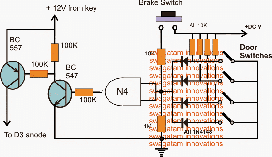
Circuit Operation
As can be seen, here we have effectively utilized the idle extra gate N4 from the IC 4093 and configured it with a few resistors and BJTs, for executing the proposed brake switch control feature.
The operations may be understood with the help of the following points:
When all the doors are closed, the relevant door switches also close and ground the positive available at the anodes of all the 1N4148 diodes. This immediately forces the input of N4 to go low due to the presence of the 1M resistor.
The low at the input of N4 renders a high at its output which in turn activates the BJTs, positioned as a switches.
However the BJTs would be still inactive as long as the positive from the key switch is not energized.
As soon as the ignition switch is keyed, the BJTs become functional and locks the motor flip flop stage by feeding a positive across D3 cathode. D3 has been introduced specifically here so that the locking potential affects only the flip flop and not the T1/T2 latch stage.
In the above mode the push button is rendered ineffective such that pressing it produces no effect on the window glasses which stays hard locked.
However the above situation gets restored each time the brakes are applied and held activated. Braking activates the brake switch, causing a positive potential at the input of N4 which in turn produces a zero at its output, switching off the BJTs. The positive at D3 cathode now becomes relieved so that the push button is enabled yet again for the intended window up/down operations.


Questions & Answers
Hi friend, this is a great idea… I wanted to ask you a question, can this circuit be modified so that instead of being used for the window motors, it is used for the car door locks? So instead of sending the signal to the motors for a few seconds, it only does so for an instant? Only to open and close the door locks with a single button? Please guide me on how to achieve this.
Thank you Joseg,
I am not sure how this design can be employed for car door locks? Because the car locks work with a solenoid, while the above circuit works with a motor, and it uses limit sensors at the extreme ends.
If you could explain your specific requirement, then i can perhaps figure it out for you!
Thanks for answering, what I have in mind is a circuit that opens and closes the door locks with a single button, these are solenoids as you mention but I have no idea how to adapt the circuit in the first image to make it work as I have planned… The thing is that my car has a single push button to open and close the door locks but its original circuit was damaged and I want to return that function to the car if you can help me I would really appreciate it.
I think you should try the following circuit, this will fulfill your requirement:
Tanks you so much you are the best my friend
You are most welcome, Joseg!
Is there a way to substitute the Relays with MOSFETS or Transistors? If so, will the circuit change completely or will only a couple of components need to be substituted?
No, it may not be possible, because relays provide quick bidirectional operation for the motors.
Hello,
Are the Capacitors Ceramic type or Electrolytic Type or Tantalum?
The ones that are with black and white bars are electrolytic, the ones that are with two black bars can be PPC type.
Hi. I assume the reeds switches are NO. Could the reed switches be replaced with hall sensors? How this would change the circuit?
Thanks.p.
Yes, we want N/O reed switches here, it will work. Hall effect sensor can make the design quite complex with additional transistor stages.
Hi. I want to have my power window drop 1″ to 2″ when I open the door and close when I shut the door. I need a 13 volt 25 amp to the motor.
Do you build and sell these circuits?
Hi, that looks difficult, not sure how the window can be opened only for 1″ or 2″.
Sorry, I don’t build and sell these products from this site.
How do I make a circuit for one power window automatic with a push trigger to stop the motor
You can give me a good gift as it is a mounted circuit
How many watt of r10
Multiply the maximum current rating of the motor with 0.6
Sir what is watts of r10
1watt or .5 watt
Thanks, but i searched on google about LM338, and it is for 5 amps , and for Golf 4 , window motor takes more maybe 10 amps .
I need something else.
Thanks you very much.
you can try the following concept:
https://www.homemade-circuits.com/2011/12/make-hundred-watt-led-floodlight.html
And how can I modify it to activate the motor, as long as I push the button.
for that you can just connect a DPDT relay with your push switch that’s all, no circuit will be required. wire the relay contacts appropriately with the motors
for safety you can add a LM338 current control to safeguard the motors
Thanks for your response.
And the first circuit, commands the motor as long as the switch is pushed ?
Or one push give command to roll window motor all the way down or up ?
just one push is enough to start the operations, the current control sensor halts the operation when the motor is no longer able to proceed and an over-current is detected.
Hello, but I want your circuit model of Car Power Window Controller Circuit , controlled with a button with two positions, one up and one down.
And to also have current control on the motors.
Without reed switches, because they need magnets to be activated.
Hello, in that case you can use the same concept which is shown in the first circuit, and connect a second switch between D2/D1 connection.
Hello how can I make a car power window controller circuit using one switch with 2 position up and down, without reed switches ?
Hello , you can use the following circuit, but the relay will need to be replaced a DPDT relay, that is with a double contact relay
https://www.homemade-circuits.com/2015/01/set-reset-circuit-using-ic-555.html
Hello,
I am interested to do the circuit with two switches. How do I calculate the value of reed switches.
Another thing, you can bring an improvement to circuit, when receiving an impulse, negative or positive, from the central locking to close the windows automatically. But for safety reasons, not to act automatically when the car is started.
Many thanks for your hard work!!!
Hello, reed switches does not require any calculation, you can procure any standard type, preferably the smallest in size.
false triggering can never happen with the above explained circuits due to the presence of C4….you an be rest assured.
wish you all the best!!
you can consider the current which exceeds the normal motor current while it is operating the window….suppose it is 5 amp then you could consider it to be 6 amps or 7 amps and solve the formula.
alternatively you could try stalling the motor manually and check how much current the motor draws and then use it in the formula.
Could you please tell me what units the current limit should be in the formula? My motor current limit is 10A, does it equal to R=0.07?
using this formula
R= 0.7/motor current limit
sir thank you for this information.
btw can i know what are the value for r2 and r4 in the first circuit?
Nuruli, you can use 10K for both
Can you dispense with reed Switch
Swadatam,
Thank you for posting this information.
My intent is to use this basic circuit to drive two motors on my muscle car which operate exhaust cut out valves. I intend to install a lighted (when valves are open) single push button latching switch in the cabin and the circuit will drive the vales open. Push the button again and unlatch the button and the light goes out and the valves close.
My question is, how do I adjust the current detection circuit to accomodate two motors?
Many thanks.
Thanks Ivan,
You can use the first circuit for your need.
Just eliminate the entire transistor stage along with the RL/2,
attach two 1000uF/25 capacitor in series with the motor wires (for each motor) making sure that the poles of the capacitor are on the same side, meaning if the positive of the capacitor is connecting the motor then it should be for both the capacitors, or if the negative of the capacitors are going to the motor, then both the negatives should be towards the motor side….
once the above is done…it's all about pressing the push button for the required actions…
Two LEDs can be used for the indications, one across positive (+) to N2 output, another from N2 output to ground…both must have a 1K series resistor limiting resistor…
Sir, I want to make Cell phone motor starter device to control and monitor electrical motor through mobile phone. Kindly guide me.
Ramkesh, you can try the following circuit:
https://www.homemade-circuits.com/2012/01/how-to-build-gsm-based-cell-phone.html
Sir, please help with calculate capacitor value after making a bridge rectifier for simple use like running 12v dc fan or using in modem (transformer as adapter)
Ram, it's not a critical factor, anything above 1000uF will serve good, for knowledge sake you can Google the info you'll probably find many sites which will provide you with all the required formulas for the same.