This circuit will give call back alerts in the form of blank calls on your cell phone whenever it senses a break in or intrusion inside the particular restricted area where it has been installed for the intended security monitoring.
Introduction
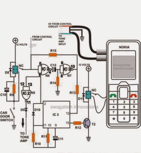
The cell phone call alert security system circuit which needs to be installed incorporates a cheap cell phone as the modem which is actually used for triggering the warning calls in the owners cell phone.
The above modem cell phone is first attached with its own SIM card as normally done with any cell phone.
For setting up the cell phone, the cover is removed and a couple of wires are neatly connected with the pads which represent the "green" button or the calling button of the phone.
After securing the two connected wires with the green button terminals, the phone is again sealed back to it normal condition.
The external ends of the above wires are then connected to the relay contacts of the control circuit as shown in the figure.
Before the installation, a call is made from the above modem cell phone to the owners cell phone so that it gets recorded inside the green button as the "last call" made from the cell phone.
Now every time the green button is activated thrice, a call gets connected to the owners cell phone.
Since the wires from the call button are connected to a relay, it simply means that if the relay contacts gets energized thrice, would result a call being sent from the above cell phone.
How the Control Circuit Works
- The control circuit basically consists of a hold circuit and a pulse circuit.
- The "hold circuit section is made up of two NAND gates configured as a timer cum latch circuit. N1 and N2 together with C12 and R14 form a timer circuit, while the resistor R15 keeps the output latched as long as the timer counts and its timing lapses.
- After which the output reverts to its original position.
- The input of the above latch is connected to a reed relay sensor which may be appropriately centered for initiating the magnetic contacts when a possible intrusion takes place.
- The reed relay activates a relay (left side of the diagram) only momentarily via the capacitor C10.
- When the above relay contacts close, N1, N2 latch, and generate a negative or a logic low at the output.
- This logic low instantly grounds the reset pin of another timer IC 4060.
- This immediately prompts the IC 4060 to start counting.
- The process generates a set of three pulses at the pin #15 of the IC activating the relay thrice via the relay driver stage. This activates the cell phone modem which starts sending a blank call to the assigned number or the owners cell phone.
- Pin #2 makes sure that the IC counting and the output from pin#15 gets locked after the three relay pulses, this is done by sending a high pulse from pin #2 to pin #11 of the IC.
- The IC remains in this position for so long as N1 and N2 are in the counting mode after which the output of N2 goes high and the entire circuit is reverted to its original state and back in the alert mode.
- The modem cell phone is kept in a charged state by employing a 7805 charger circuit.
This circuit was exclusively designed and invented by "Swagatam".
PARTS LIST
All Resistors are ¼ watt 5% CFR, unless otherwise stated.
R9-10K,
R10-2M2,
R11-330K,
R12-4K7,
R13-39K,
R14-1M,
R15-1K,
C10/C12-100uF/25V,
C11-0.001uFDISC,
D9/D10-1N4148,
D8/D11-1N4007
T2 = BC547
IC2 (N6,N7,N8)-4093
IC3-4060
Relays-12V/400 Ohms


Questions & Answers
Hi – I would like to build the above circuit but there is no IC 1 in the part list and in the drawing IC3 has pin 15, but it’s only a 14 pin ic. Please clear up this confusion
Hi, sorry for the confusion, this design was a part of another elaborate car security circuit which had IC1, but this design does not include the IC1, so only IC2 and IC3 are present. IC3 is IC 4060, I have corrected the parts list now, please check it.
For the original post you may refer to the following article:
https://www.homemade-circuits.com/build-homemade-gsm-car-security-system/
i would like some help improving this even further.
Lets make it a home security system. Which is possible to operate under a powercut.with a 12v rickshaw battery.
Lets add 6 motion sensors and and a 12 V car alarm which goes off for only 1 hour.
And ability for owner to call back the telephone number of the security system and turn off Alarm !
Thanks a lot! You were a lot of help!
Hello, thank you very much,
Pin#14 of the IC is +Vcc for the IC 4093.
N2/D9 here is an optional connection which can be connected to an external load such as an momentary alarm, etc…since this diagram was extracted from one of the other articles, the tone amp is actually related to that article, you may read it here
https://www.homemade-circuits.com/2011/12/build-homemade-gsm-car-security-system.html
Hi Swagatam,
I want to use 4 x 1.5V batteries instead of a 12V source to make it portable. Problem is I don't think I can get a relay which will operate at such a low voltage. Can I substitute the speed dial relay for some kind of solid state device. I have noticed that touching the copper speed dial contacts with a finger is enough to activate the phone (high impedance/capacitance?)
Hi John, it can be probably done by using bidirectional electronic switch such as in IC 4066….any other method is not recommended
Hello pls I am having problems with the simulation of the diagram pls can u help me out with a recomended simulation tool?
sorry I don't use simulators, so I won't be able to recommend any.
Hello pls I am having problems with the simulation of the diagram pls can u help me out with a recomended simulation tool?
Swagatam will it be feasible for you to share the parts list for this mentioned project.
you are welcome!!
Thanks swagatam
Hafeez, I'll surely try to update it when I'm free…
i want this project for final year with if anyone open my door then i receive a call or sms or alarm on my cell from system send me cost
you can try making the last circuit shown in the following article:
https://www.homemade-circuits.com/2011/12/build-homemade-gsm-car-security-system.html
hi sir, i found out that i can't finish my project using the speed dial because i don't know how to make an IC to produce longer signal enough to activate the speed dial feature of the cellphone. It's because if its relay will switch on the pad on a short pulse, the cellphone will not understand it as a command for speed dialing. Such will only be understood by the cellphone as encoding a single numeric character.
In summary I need the circuit to also produce
1. several short pulses (to reset the mobile to Home menu)
2. then single long pulse ( longer than 4 seconds) to activate speed dialing a number. I understand IC4017 can produce this long pulse, but i don't know how to integrate it to the system, minimizing the use of relays.
Kindly help me.
Thank you
…..you have emailed me the block diagram…sorry that won't be of much help!
Hi Uel,
Please show me the entire schematic and specify the points at which you want the long pulses and the short pulses, I'll try to help you out.
pls show me your circuit diagram, only then I'll be able to suggest my opinion correctly.
three pulses won't be possible with a 4060 IC, you can get either 4 or 8 or 2, meaning in multiples of 2…. you will have to design completely different circuit for it.