In this article I have explained a model locomotive controller circuit using uniquely set IR beams for different locomotives allowing unique identification signals and controls for the engines. The idea was requested by Mr. Henrik.
Technical Specifications
Thank you very much for all your circuits / schematics. I will for sure build many of them.For my model train I would like you to help me out finding a way to identify the locomotives parsing a point. All the locomotives are equipped with a digital decoder. The system is Märklin Digital. Since we (my son and I) have a quite large model train track (100 sq. meters) with more than 50 digital locomotives. I have developed a Windows based software system to help us run the system. That was the easy part.In order for my software to stop a train at the train station it is necessary to know an ID of the train. I was thinking about maybe RF Tags but how to read the Tag? We have a lot of tracks so therefor I can’t use the ordinary RF Tag reader. So maybe RF Tags is not the right approach to this. Maybe a unique Infrared signal could be used. The only thing I need is a unique number / signal for each locomotive. I can design the software to mach this number to the locomotive. The max. distance from the locomotive to the reader would be about 5 cm.Please continue the good work you do. It is very helpful when experts like you help us rookies.Best regards, Henrik Lauridsen
The Design
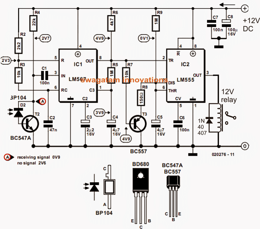
For acquiring a precision signal IDs for an application such as the above, a simple LM 567 IC circuit becomes extremely handy.
As may be witnessed below, the first circuit forms the precision IR receiver unit while the next one functions as the IR transmitter circuit
R2/R3/C2 sets the receiver unit with a unique frequency such that the IC LM567 responds only to this frequency across its pin#3 via the IR photo diode BP104. It implies that the circuit will not respond to any other frequency other than the one determined by the corresponding RC network across its pin#5,6.
On detection of this frequency, the IC grasps and latches on to the signal creating an immediate low at its output pin#8, which is appropriately used for triggering a monostable made out of the IC 555.
The monostable responds to this turning ON its output at pin3 and activating the relay.
The above activation is held intact for a predetermined time period even after the input IR frequency is removed, as fixed with R9/C5.
The transmitter circuit shown in the next diagram is supposed to be used for triggering the receiver unit, and therefore must be tuned to a frequency matching the set frequency of the receiver unit.
For achieving the intended frequency R1/C1 may be tweaked until the exact desired signal is reached and is compatible with the Rx frequency.
Alternatively a standard IC 555 astable may be also tried for implementing the Tx functioning.
The Circuit Diagram
![]()


Questions & Answers
Dear Swagatam
Perhaps, you misunderstood me. I am 100% sure about my point. Let's take your example, if 3 of those 7 locomotives + 2 other locomotives (total 5) are to be stopped at another station, how the receiver at that station will sense two different frequencies. Similarly, if at some station 3 locomotives assigned with 3 different frequencies are to be stopped how the sensor will sense them?
I do have a solution for that but, as I already stated earlier, my view point could be wrong and you also said the same thing. So we should wait for Mr. Lauridsen or you may ask him by email for clarification so we may have exact details of his requirement and then get him more better solution.
OK, Thank you Abu-Hafss,
Mr. Henrik has explained his requirement in detail, I'll soon publish it in the above article or as a new article.
Hi Swagatam
A barcode reader is an input device which consists of a scanner , a decoder (either built-in or external), and a cable used to connect it with a computer. Because a barcode reader merely captures and translates the barcode into binary numbers, the data must be sent to a computer so that a software application can make sense of the data. Therefore, I don't think that its output can activate a transistor etc.
Thank you Henrik, appreciate your response.
Hi Swagatam,
Thank you very much for your solution. This is going the right way and I like this very much. I am happy to have found you. Not many experts can / will spare time as you do on helping novices like me. I will send you an email later.
….I wanted to know if a relay could be used with the bar code output, just as we have from an Arduino or from any other MCU circuit.
If you say everything else will be handled by the software connected with the bar code, then probabaly the discussion would end here.
The above sentence sparked an interesting idea for solving the above locomotive issue.
we can use a frequency filter network that would detect and respond only to the assigned range of frequencies? and allow only those locos that are assigned within those specified frequency ranges.
Hi Abu-Hafss,
Thanks for the nice idea, but this is too complicated and time consuming, just imagine one will have to configure the blues strip of each train, then make 4017 cascaded design and then set each train to respond on each platform.
Regarding the bar code issue, the question was asked by me, so I expecting the answer for myself not for Mr. Henrik:)
Since you proposed the idea of the bar code I thought you knew in detail how the output of the bar code could be configured for acknowledging a particular set frequencies, so that it could be applied for any other application too.
Swagatam
My idea is based on the assumption that all the locomotives are of same size and they travel at same speed when crossing the sensor. Please refer to the attached diagram for understanding the following para.
The blue line on the locomotive may be divided into 51 (1+50) equal divisions (50 being the number of locomotives). Let the first division (starting from right) be DIV-0. In this DIV-0 (first division) of each locomotive a marker strip is placed such that it is jutting out from the side of the locomotive. This would be the start marker. Then after a calculated space another similar marker is placed in the next division which is DIV-1. This marker will represent the train number (now, Locomotive #1 is ready). Similarly, on another locomotive the train number marker is placed in DIV-2 for Loc#2 and then in DIV-3 for Loc#3, DIV-4 for Loc#4 and so on. Alternatively, 2 IR-LEDs on each locomotive can do the same job, perhaps more neatly. But, since I have no idea of the length of each locomotive, I proposed the strip markers.
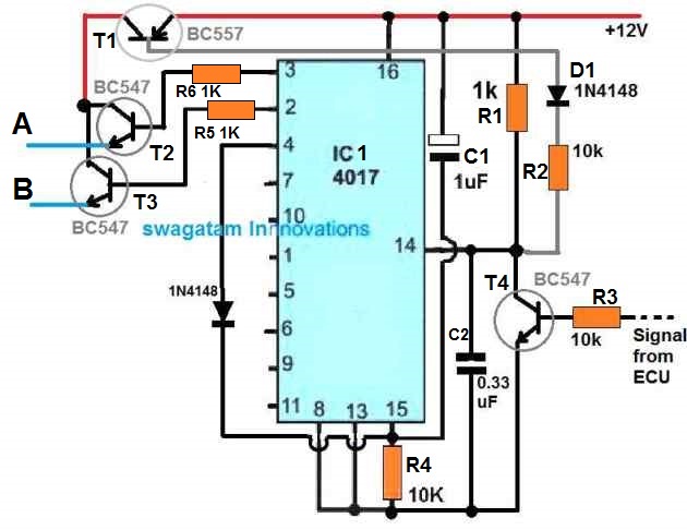
Okay now, when the first marker/LED crosses the sensor, a 555 configured as astable oscillator is triggered which provides CLOCK signal at some suitable frequency to a network of 7 cascaded CD4017s. When the next marker/LED crosses the sensor, the 555 is stopped and a high output at one pin of a certain CD4017 will correspond to this specific locomotive. The working principle would be similar to that of an electronic dice circuit but with 50 outputs instead of 6.
Frankly speaking, I have never played with cascaded 4017s therefore, I have simply narrated my idea instead of schematic.
Regarding your question about the barcode, all movements of trains are being controlled by the software as Mr. Lauridsen had mentioned. He has just asked for a sensing set-up to identify each train. Therefore, the barcode reader is simply responsible to read the barcode and inform to the software. Depending upon the settings, the software will decide whether to stop or let the train pass the station. The reader has nothing to do with the movement of the train. 🙂
Hi Abu-Hafss,
yes 4017 is a possibility, in the previous comment I suggested a sequentially adjusting frequency circuit… I was referring to a 4017 option.
Please post your idea as soon as you finish it.
And also if possible please let us know how the bar code device would work to operate a relay inside the vehicle in response to the various frequency detection.
Good day, Swagatam
Yes, each locomotive can be assigned a unique bar code. A bar code reader installed at each station can sense it and rest the software will do the job.
I have also another idea based on 4017. Let make its draft and then share with you.
In your previous comment you had mentioned about bar code reader, can the idea take care of the problem suggested by you?
Dear Abu-Hafss,
Now you have addressed the issue correctly.
Even under such random conditions we wouldn't require 50 sensors on each platform, just a few numbers would do. Or some arrangement could be made with a single installed unit to produce a predetermined sequentially changing frequencies after a set period of time.
Hi Swagatam
What I understand is that Mr. Henrik Lauridsen needs some sort of sensing circuit to identify that a certain train is approaching the station so that it can be stopped or not. Your approach means to install a transmitter circuit on each locomotive and also its matching receiver at each station i.e. 50 sensing (receiver) circuits at each station!
Maybe I am wrong but, there should be one sensor installed at each station which should read 50 different IDs or frequencies or signals corresponding to 50 trains. Mr. Lauridsen would clarify this point.
If this is the case, he can use a bar code reader or QR code reader. One code reader could be installed at each station and each locomotive can have a unique identification bar code or QR code tag pasted.
I don't know if a QR code reader can respond quickly against a moving locomotive but, a bar code can certainly do (a practical example of departmental stores).
Abu-Haffs,
the question was raised by you, and I have presented the clarification for you….but if you are not sure about your question then indeed it could be a wastage of time discussing.
Swagatam
I think it would be better to wait for Mr. Lauridsen to come in and clarify this issue otherwise, our discussion will be baseless and simply wastage of time.
Thanks Abu-Hafss,
However I think one Rx would be enough in every station. Suppose a particular station is assigned with a 100kHz Rx freq to stop 7 numbers of locomotives, then these 7 particular locos could be assigned with the corresponding 100kHz Tx for ensuring a halt over that station.
The above may not be effective if we have a situation where the locos would have randomly changing halting pattern across the stations….I may be wrong though but this how I perceive it to be.