In this post I will show how to construct a farmer friendly GSM pump motor controller circuit which could
turn on and off the irrigation system remotely from anywhere in the world via cellphone SMS and return you with an acknowledgement message. The idea was requested by Mr. PG Ragavandir.
The Design
Agriculture is one of biggest industry in India which serves food for more than a billion people every year. Producing vast amount of food is never an easy task; irrigation is one of the factor.
Most of the agriculturist’s crop field is situated far from their residence, just turning on the water pump costs huge for their transportation per year.
India is known for IT skills and space programs and reached mars less than cost of movie “Gravity”, this signifies the great potential among Engineers and Scientists. But, the skills are not uniformly distributed across different fields; agriculture is one of the field where technological development is slow.
This SMS based GSM pump motor controller takes a baby step towards agricultural development, this may not be a revolutionary project but, it may bring delight among agriculturists.
Let’s dive into technical part of the project.
The project is designed with minimal hardware components so that a beginner can accomplish it with ease.
The circuit consists of power supply, which powers the whole setup.
The Arduino is the brain of the project which take decisions and GSM modem which sends and receives text SMS and communicate with the user and relay which controls the motor.
How it Works
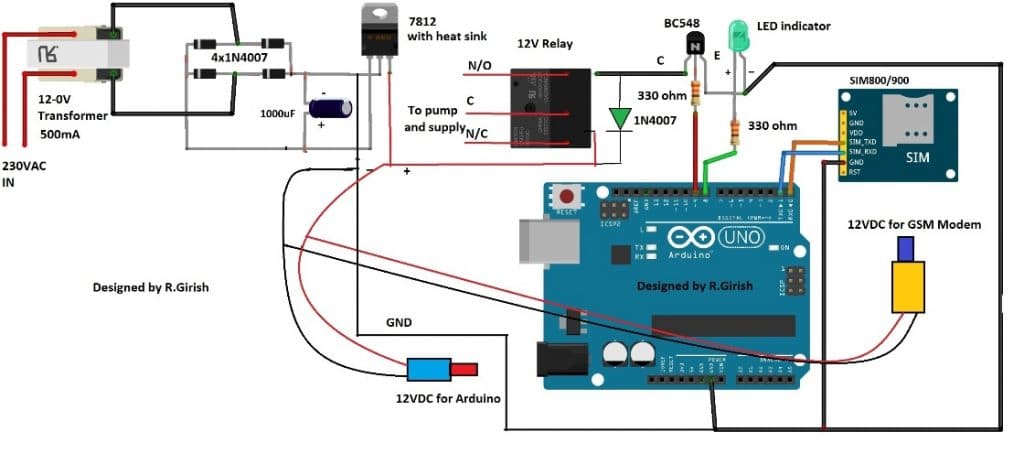
Note: Please use at least 10K resistor at the base of the BC548 transistor, 330 Ohms is too low.
The transformer step down the 230VAC to 12VAC and bridge rectifier convert AC onto DC current and the current passes through an electrolytic capacitor to smooth the power supply.
A fixed 12V voltage regulator gives power to arduino, GSM modem and relay. The GSM modem is connected to arduino at pin #0 and pin #1, which are RX and TX respectively.
The RX of GSM is connected to TX of arduino and TX of GSM is connected to RX of arduino. If you are confused, just look at the below diagram, misconnection will not send or receive SMS.
ARDUINO TX----------------------RX GSM modem
RX----------------------TX
Ground to ground connection is also established between arduino and GSM modem.
Try to get a male jack power connector for the GSM and arduino, if not just solder the wires directly from power supply to arduino and GSM, which might increase the mess in the project.
The transistor drives the relay and the diode protects the circuit from high voltage spikes while switching the relay ON/OFF.
The LED indicator shows the status of the relay. If the LED glows the relay activated and if the LED is off, the relay is deactivated.
Insert a valid SIM on the GSM modem and try to take advantage of the offers availed by the network provider for SMS such as rate cutters, which will reduce the expenses for SMS.
Program Code:
//---------------- Program developed by R.Girish ----------------//

int LED   = 8;    // Status LED pin
int motor = 9;    // Motor relay control pin

int temp = 0;     // Flag to indicate end of command reception
int i    = 0;     // Index for command buffer

char str[15];     // Buffer to store received SMS command

//----------------------------------------------------------------
void setup()
{
  Serial.begin(9600);          // GSM module baud rate

  pinMode(motor, OUTPUT);     // Motor relay output
  pinMode(LED, OUTPUT);       // LED output

  digitalWrite(motor, LOW);   // Motor OFF initially
  digitalWrite(LED, LOW);     // LED OFF initially

  // Give GSM module enough time to register to network
  delay(20000);
  delay(20000);
  delay(20000);

  // Enable new SMS indication directly on serial
  Serial.println("AT+CNMI=2,2,0,0,0");
  delay(1000);

  // Set SMS text mode
  Serial.println("AT+CMGF=1");
  delay(500);

  // Send startup confirmation SMS
  Serial.println("AT+CMGS="+91xxxxxxxxxx"r"); // Replace x with your mobile number
  delay(1000);
  Serial.println("System is ready to receive commands.");
  delay(100);
  Serial.println((char)26);   // CTRL+Z to send SMS
  delay(1000);
}

//----------------------------------------------------------------
void loop()
{
  // If a full command is received
  if (temp == 1)
  {
    check();        // Process the received command
    temp = 0;       // Reset flag
    i = 0;          // Reset buffer index
    delay(1000);    // Small delay for stability
  }
}

//----------------------------------------------------------------
// Automatically called when serial data is received
void serialEvent()
{
  while (Serial.available())
  {
    // Look for starting delimiter '/'
    if (Serial.find("/"))
    {
      delay(1000);  // Wait for complete message

      while (Serial.available())
      {
        char inChar = Serial.read();
        str[i++] = inChar;   // Store character

        // Look for ending delimiter '/'
        if (inChar == '/')
        {
          temp = 1;          // Command received completely
          return;
        }
      }
    }
  }
}

//----------------------------------------------------------------
// Function to compare received command and take action
void check()
{
  // Command: motor on
  if (!(strncmp(str, "motor on", 8)))
  {
    digitalWrite(motor, HIGH);   // Turn motor ON
    digitalWrite(LED, HIGH);     // LED ON

    delay(1000);
    Serial.println("AT+CMGS="+91xxxxxxxxxx"r");
    delay(1000);
    Serial.println("Motor Activated");
    delay(100);
    Serial.println((char)26);
    delay(1000);
  }

  // Command: motor off
  else if (!(strncmp(str, "motor off", 9)))
  {
    digitalWrite(motor, LOW);    // Turn motor OFF
    digitalWrite(LED, LOW);      // LED OFF

    delay(1000);
    Serial.println("AT+CMGS="+91xxxxxxxxxx"r");
    delay(1000);
    Serial.println("Motor deactivated");
    delay(100);
    Serial.println((char)26);
    delay(1000);
  }

  // Command: test
  else if (!(strncmp(str, "test", 4)))
  {
    Serial.println("AT+CMGS="+91xxxxxxxxxx"r");
    delay(1000);
    Serial.println("The System is Working Fine.");
    delay(100);
    Serial.println((char)26);
    delay(1000);
  }
}

//---------------- Program developed by R.Girish ----------------//
NOTE 1: While compiling the program it shows a warning, which you can ignore it. The program is verified and tested.
NOTE 2: Please remove TX and RX connection from arduino while uploading the code.
NOTE 3: Replace “xxxxxxxxxxxxx” with recipient’s phone number in 4 places in the program.
NOTE 4: Please purchase a GSM modem without power button in the module; in case of power failure it won’t latch in into mobile network unless you manually press the button, so avoid such type of GSM modems. The GSM modem one without power button will latch into mobile network directly after power retains.
Author’s Prototype of GSM Pump Motor Controller Circuit:
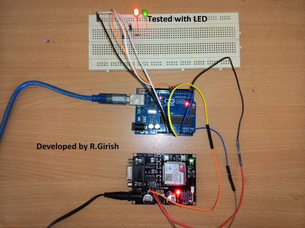
How to use the above setup:
• Send /motor on/ SMS from your cellphone to activate the relay.
• Send /motor off/ SMS to deactivate the relay.
• Send /test/ SMS for testing the response from the circuit.
Make sure you start the command with”/” and end with “/” otherwise it won’t accept as valid request.
• /motor on/ will turn ON the relay and return with an acknowledgement SMS “Motor Activated.”
• /motor off/ will turn off the relay and return with an acknowledgement SMS “Motor Deactivated.”
• If you send /test/ it will return with an acknowledgement SMS “The System is Working Fine.”
• The above message signifies that your setup is working fine.
• If no acknowledgement is returned to you can assume that no action is preceded on the motor and you may troubleshoot the problems.
• After powering the setup ON wait for 1 minute the system will send an acknowledgement SMS “System is ready to accept commands.” once you receive this SMS your project is ready to serve.
The above commands are fool proof and never trigger the motor falsely, the setup will not respond any SMS other than the above specified commends.
Improving the above Concept
This above GSM pump application circuit attracted lots of readers and we have received tons of queries and suggestions. One of the avid readers of this website Mr.Gandhi suggested a good improvement to the prior design.
SMS Acknowledgement When Motor is Actually ON
The improvement is all about the revert acknowledgement, where the user will receive a SMS response in his cellphone from the GSM pump controller system when a user sends a valid SMS comment.
The existing design sends an acknowledgement SMS to the user independent of the actual state of the relay i.e. ON/OFF.
The new design change suggested by Mr.Gandhi checks the state of the relay whether the relay is physically switched its state or not.
The change as per this new GSM water pump controller design can be implemented to the previous design without much hassle by adding a feedback system as shown in the schematic and uploading the new code.
Circuit Diagram:
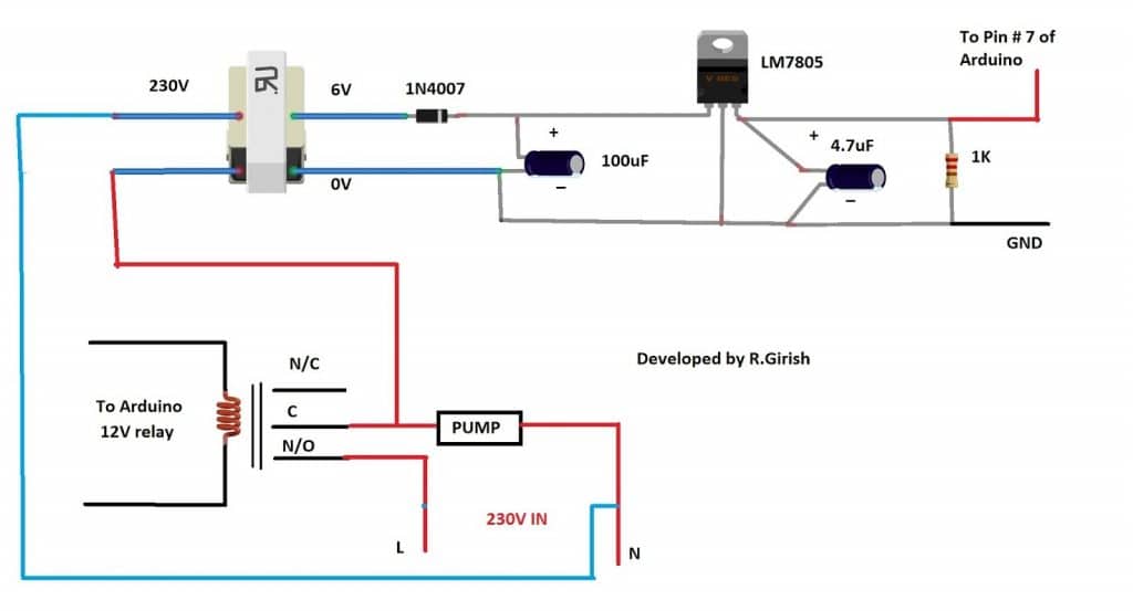
When we send SMS command “/MOTOR ON/” the pin # 9 goes high and trigger the relay ON. If the relay connects the common and N/O pins the pump starts and also turns ON the transformer which will give +5 at the output.
The +5V signal is fed to pin # 7 which will confirm and return with an acknowledgement “Motor activated”.
When we send “/MOTOR OFF/” the pin # 9 turns LOW and relay disconnects the common and N/O pins, this will turn off the pump as well as the connected transformer. The output at pin # 7 goes LOW and returns with an acknowledgement “Motor deactivated”.
If no acknowledgement SMS is received in your cellphone, we can confirm that no action was taken and the pump is at the last requested state, you may go to the site and troubleshoot or no acknowledgement is received due power cut.
Program Code:
//---------------- Program developed by R.Girish ----------------//

// Pin definitions (do NOT change to keep circuit intact)
int motor = 8;      // Relay / Motor control pin
int LED   = 9;      // Status LED
int ack   = 7;      // Acknowledgement feedback pin

// Variables for SMS parsing
int temp = 0;       // Flag to indicate full command received
int i = 0;          // Index for character buffer

char str[15];       // Buffer to store incoming SMS command

void setup()
{
  // Initialize serial communication with GSM module
  Serial.begin(9600);

  // Pin configuration
  pinMode(ack, INPUT);
  pinMode(motor, OUTPUT);
  pinMode(LED, OUTPUT);

  // Ensure outputs start in OFF state
  digitalWrite(motor, LOW);
  digitalWrite(LED, LOW);

  // GSM module startup delay (network registration time)
  delay(20000);
  delay(20000);
  delay(20000);

  // Configure GSM module for direct SMS display
  Serial.println("AT+CNMI=2,2,0,0,0");
  delay(1000);

  // Set SMS text mode
  Serial.println("AT+CMGF=1");
  delay(500);

  // Send startup confirmation SMS
  Serial.println("AT+CMGS="+91xxxxxxxxxx"r"); // Replace with your number
  delay(1000);
  Serial.println("System is ready to receive commands.");
  delay(100);
  Serial.println((char)26);   // CTRL+Z to send SMS
  delay(1000);
}

void loop()
{
  // If a complete command is received
  if (temp == 1)
  {
    check();        // Process the command
    temp = 0;       // Reset flag
    i = 0;          // Reset buffer index
    memset(str, 0, sizeof(str)); // Clear buffer
    delay(1000);
  }
}

// This function automatically runs when serial data arrives
void serialEvent()
{
  while (Serial.available())
  {
    // Look for starting delimiter '/'
    if (Serial.find("/"))
    {
      delay(1000);

      while (Serial.available())
      {
        char inChar = Serial.read();

        // Store character safely in buffer
        if (i < sizeof(str) - 1)
        {
          str[i++] = inChar;
          str[i] = ' ';   // Always keep string terminated
        }

        // End delimiter '/' detected
        if (inChar == '/')
        {
          temp = 1;        // Signal full command received
          return;
        }
      }
    }
  }
}

// Command processing function
void check()
{
  // Turn motor ON command
  if (!(strncmp(str, "motor on", 8)))
  {
    digitalWrite(motor, HIGH);
    delay(100);

    // Check acknowledgement feedback
    if (digitalRead(ack) == 1)
    {
      digitalWrite(LED, HIGH);
      delay(1000);

      Serial.println("AT+CMGS="+91xxxxxxxxxx"r");
      delay(1000);
      Serial.println("Motor Activated");
      delay(100);
      Serial.println((char)26);
      delay(1000);
    }
  }

  // Turn motor OFF command
  else if (!(strncmp(str, "motor off", 9)))
  {
    digitalWrite(motor, LOW);
    delay(5000);

    if (digitalRead(ack) == 0)
    {
      digitalWrite(LED, LOW);
      delay(1000);

      Serial.println("AT+CMGS="+91xxxxxxxxxx"r");
      delay(1000);
      Serial.println("Motor deactivated");
      delay(100);
      Serial.println((char)26);
      delay(1000);
    }
  }

  // System test command
  else if (!(strncmp(str, "test", 4)))
  {
    Serial.println("AT+CMGS="+91xxxxxxxxxx"r");
    delay(1000);
    Serial.println("The System is Working Fine.");
    delay(100);
    Serial.println((char)26);
    delay(1000);
  }
}

//---------------- Program developed by R.Girish ----------------//
The above implementation is not practically tested, but the author is cent percent sure that above idea will work. If readers found any issues with the above improvement can express through the comment section.
Part List
1) Transformer step down 12-0V
2) Diodes IN4007 x5
3) LM7812 x1
4) Relay 12V x1
5) BC548 Transistor x1
6) Electrolytic Capacitor 1000uF x1
7) GSM module: SIM 800 or SIM 900 model
8) 330 Ohm Resistor x2
9) LED RED/GREEN x1
10) Arduino Uno or Arduino nano or Arduino Mega
11) DC male jack x2
Video Clip:
Integrating with 3 Phase Motors
I have been receiving many requests to upgrade the relay stage for the above design so that it becomes compatible for operating 3 phase motors using GSM cell phone commands.
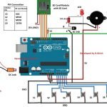
Therefore I decided to design the required circuit which will hopefully be able to switch ON and switch OFF a given 3 phase motors having the typical start and stop contactor mechanism.
The following figure shows how to configure the design using an IC 4017 circuit.
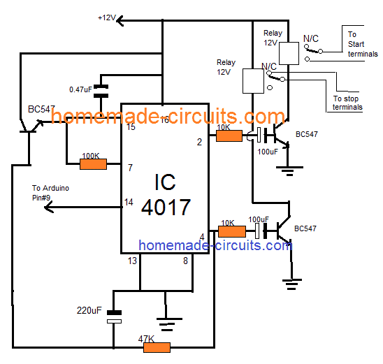
NOTE: The 100uF /10K and 220uF and 47K values may need some adjustments in order ensure the correct amount of delay for the respective transistors and relay stages.


Questions & Answers
Hello sir ,
Thanks for the wonderful project and very good explanation ,
Sir me and my team are going to Perform this project in our college so i want to know from u that , what new advancements can be made right now …
Glad you liked it Abdul, However since I am not very good with Arduino suggesting new advancements can be difficult for me through codes.
sir we are doing the same project we need literature overview, plz point us the problems in your sys, how is it diffrent
Hello ashfaq, the literature is already given in the article with full details.
What is the price of project?
helo bro second tutorial is not working,, when i send motor on,, it getting on but im not getting any message,, when i send off ,, its getting off and im getting message also,, for experiment i given 5 voltage via relay,, but input 7 is not working
Hello Mahendhar, as you can see the circuit is working in the video. I would suggest you to do the exact set up as indicated in the diagram and check again.
Hello, swagatam sir our seniors made the project of gsm based single phase pump motor,so now this year we have a job to make it gsm based 3 phase pump motor. Sir we need help ASAP i hope u’ll get my msg , i have seen th circuit diagram above but i am not getting it . We need to control the starter may b u have any idea to make it possible and we need to change the coding a little bit ,sir i hope u’ll contact me soon….
Hello Shubham, I am not good with Arduino coding so modifying the code can be difficult for me. However for the starter section I may investigate if you could tell me about its specifications.
The last 4017 circuit is actually designed to operate a start/stop based contactor box.
Hi Swagatam,
Like your project but question in my mind,
In case of power failure, does GSM module alert user by sending a SMS back.
if its not, can we make it possible as I am working on a project where need to monitor a fan basically I required a solution which in case fan goes down, it generate a sms to alert users for potential action.
Thank you Pratap,
The pin#7 is designed to accept the input prompts. It can be arranged with a transistor circuit such that it triggers pin#7 of the Arduino whenever power fails, and prompts the GSM to send a message to the owner regarding the actions. However for this the GSM and the Arduino must have the facility of a battery back up.
Thanks for reply,
There are few more things that I want to discuss can we talk in personal through email
You can feel free to discuss it here, I’ll try to help you if possible!
Sure, is it possible if you can provide me the circuit design of my model with codes
Sorry, actually I am not good with Arduino coding, so it can be difficult for me to create new codes. There are many experts in the Arduino.cc forums, where you can ask how to modify the second program from the above article as per your requirement. Hopefully somebody would be able to guide you in the right direction.
Pls modified this code to dual mobile control the gsm pls help us
Thank you very much for your usual cooperation,
I’m OK with that , but the delay time is 3min in my case is too much.
Can you adjust it less than 10 seconds
You can replace the 470uF capacitor with 22uF/25V for getting a value around less than 10 seconds
Thank you very much,
I’m a beginner in electronic
Can you give me something simple for controlling my led panel indication light, 230v 1watt
Thank you
OK, here’s another simple design that you can try:
https://www.homemade-circuits.com/2016/07/alternate-switching-relay-timer-circuit.html
Hi Mr swag, thanks you very much for always sharing us with your innovations and research, may God richly go as yo.
My problem is I need your usual help, I want a circuit to blink led panel light without arduino, below are its spec: 230v ac 1 watt
Hopping to hear from you soon
Thanks Stephen, you can try the following concept:
https://www.homemade-circuits.com/2015/12/220v-dual-alternate-lamp-flasher-circuit.html
you can remove one of the triac stages and keep any one of them for the required flashing.
I have tried the circuit and works very well and am very great full for offering the circuit free!however I would request an upgrading where one can control two pumps independently or one pump with two independent solenoid valves and incorporate a flow switch
I am so glad you liked it, will surely consider your request and update if it is possible!
sir,
How much time it will take to complete the project,from basic level????
Mohan, it will depend on the user, how quickly he is able to grasp and implement it.
Sir update the moter controll system on and off using 2relays with missed call and SMS system and using time setting futeru. Like Kisan raj (or) maharaj product
We’ll surely try to update, if it’s possible, thanks for the suggestion!
sir ic 4017 circute is not working
So give me solution (or) another circute plz………Sir
Sudheer, it will definitely work, please take the help of an expert in your area…you will have to first confirm the relay operations on work table and then implement in actual project.
you will have to understand the circuit and then implement it step wise
can i use sim800l module for this project
sorry I have no idea about it….
Sir how to control 3 phase motor by using this project
Madhu, what kind of switch do you have for your 3 phase motor?
Push button
start and stop type??
No sir, green button for start and red button for stop
I’ll try to find a solution for this soon…
Hi Swagatam.!
I am having trouble with this project. I used first code it worked fine. But after some days i turned it on GSM module sim900a wasn’t detecting signals light was blinking fast every second. Then after several hours of this madness of separating supplies for both arduino and GSM module (by making sure its 12v – 3A for GSM) and changed sim cards several times it started to detect network. But it stopped communication with arduino. I’m completely puzzled into it. I have to submit it to my university. please help me..!
Hi Mandira,
I think your GSM module is malfunctioned somehow, better replace with new one.
Don’t use Jio simcards as it is 4G only network.
Remove the GSM’s module all wire connections and just insert SIM and turn ON and try to give a call to GSM and you should hear ringing, if not replace the GSM module and the network LED should blink only every 3 seconds, blinking every one seconds signifies searching for network.
Regards
Hey GR, is it normal for a GSM module what i mentioned below:
I connected rx tx to arduino, the arduino is powered on while i didn’t power GSM module. But through the connection of rx tx and ground the lights on GSM are turned on. They are not very bright but they are turned on. Its strange. Do you have any idea if this behaviour of module is normal. Because may be this reason blown the previous GSM module rx tx pins
Hi Mandira,
I too faced the glowing of LED by just powering the Arduino with connection with GSM (Tx, Rx, GND), but don’t do this again, either turn on the both boards simultaneously or power the GSM board first and power the Arduino.
This could probably malfunction the GSM, I have done this couple of times accidentally but nothing gone wrong yet.
Regards
Thanks for this quick response. Yes the GSM light is blinking every 3 seconds it means it detected the signals and registered to the network. The problem is it has no communication to arduino through RX TX when calling on the number it gives ringing. But has no output. Even when i checked the pins RX,TX with oscilloscope and called that number. Nothing appeared on oscilloscope. Probably there’s a shortage between these rx,tx pins. I think i need to replace it right now.
Thanks Swagatam & GR you guys are great.
You are welcome Mandira. We are always happy to help!
Hi Mandira, I’ll try to contact the author of the article and try to get the solution soon.
I have done this project it is working fine thank you very much
I am glad it worked Madhu, please keep up the good work