If you are looking for a simple circuit to test continuity of wires and long conductors, the explained 7 easy to build continuity circuits are the ones which you can try and might fulfill your requirement.
What is a Continuity Tester
A continuity tester is a device which is used for identifying the correct continuity of a particular conductor in question. Or in other words the device may be used for tracing faults or breaks in a particular conductor or a wire.
The device is actually a simple LED and a cell circuit, where the LED is made to switch by passing the cell voltage to the LED via the conductor in question.
If the conductor is not broken, the cell voltage circulates through it and reaches the LED to complete the circuit and in the course illuminates the LED, providing the relevant information.
If the conductor is open internally, the cell voltage is unable to complete the circuit and the LED remains shut OFF, indicating the fault.
1) Using One LED and Resistor
The first circuit diagram shows a very simple continuity circuit where only a LED/resistor set up along with a 3 volt source is used.
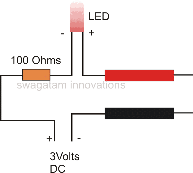
The prods are connected across the ends of the wires or the conductor which needs to be checked. The results regarding the status of the wire is achieved as explained above.
However this circuit is quite crude and won't be able to check big cable networks where the fed voltage may drop substantially in the path and might fail to illuminate the LED properly.
For checking complex and large wire or cable bundles, rather a much sensitive circuit may be required.
2) Using Two Transistors
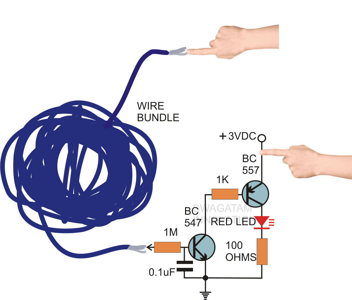
The next circuit shows a configuration which is much rugged and highly sensitive.
Moreover the wire ends may be checked via finger touches, which simply avoids th need of lengthy prods from the continuity tester.
The circuit employs a couple of cheap hi-gain transistors which are coupled together in such a way that the over all gain of the circuit becomes very high.
Even a few milli volts is enough for making the circuit conduct and illuminate the LED.
The connections can be seen in the figure, how through easy finger touch operations, even the staus of big wire bundles may be identified in seconds.
If the wire bundle is without breaks, the LED lights up brightly, and in case the wire is open somewhere, keeps the LED completely shut OFF.
This sensitive circuit can also be used as a line tester, the 3volt point is held with hand, and the 1M end is touched to the point where the LINE presence needs to be tested.
The presence of phase, lights up the LED and vice versa.
Video Demonstration
3) Using LM3909
The following miniature tester is built using just 4 inexpensive components, and operated from a AAA 1.5 V dry cell. It can be used for testing continuity tests across wiring harnesses and on circuit networks, through appropriate test prods hooked up to points A and B.
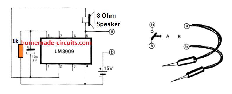
After some trial and error effort, you will be able to perfectly judge the contact resistance by comparing the differences in the level of the sound frequency.
Another great application of this unit could be in the form of a mini siren or simply as a morse code practice which can be done by connecting a morse key between A and B.
4) Simple Continuity Tester Circuit using IC 555
In the following second project learn how to make a simple continuity checker circuit using 555 timer. And what makes this circuit so special is that no transistor is used in it and hence this is indeed the simplest continuity checker.
By Ankit Negi
We all know the importance of 555 TIMER in electronics.
The fact that they are used even today, 45 years after their first appearance in electronics industry makes it a key component of our day to day circuit.
There’s hardly anything this 555 timer cannot do for you. From using it as a clock generator to voltage regulator. And so here we are, making yet another very useful circuit using this invincible IC.
As we already know a continuity checker is a simple electronic tool that checks the continuity between two terminals of a circuit. For let’s say you have a wire, which you want to check for continuity.
So you have to just connect its two terminal to the continuity checker and if there’s no break in the circuit it will indicate it( either by a glowing led or buzzer) and if there’s break than nothing will happen.
COMPONENTS REQUIRED:
1. A 555 timer
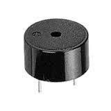
2. One buzzer ( **if you do not have buzzer then use LED)
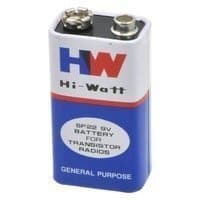
3. 9v battery
4. One 4.7 k resistor
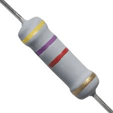
5. One 47 k resistor

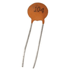
6. One 10uf ceramic capacitor
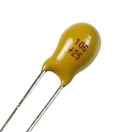
7. One 0.1 uf ceramic capacitor
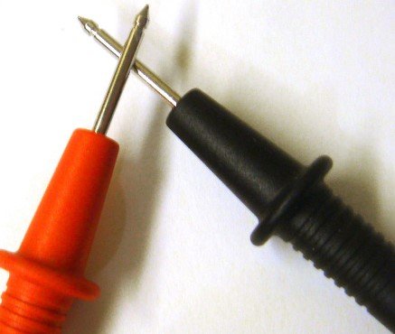
8. Two connecting probes( red and black)
Circuit diagram:
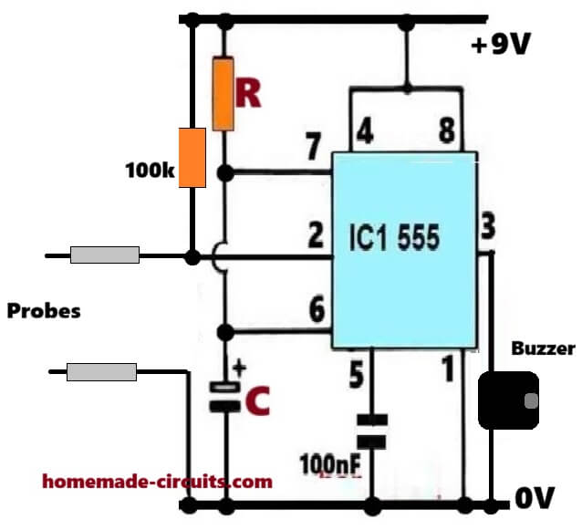
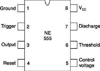
There are total 8 pins in 555 timer as shown in circuit diagram make connections as shown and don’t forget to connect capacitors as they are as important as any other components in this circuit.
Connecting probes are connected between trigger terminal (2) and ground.
**If you do not have a buzzer than connect led in series with 1k resistor in place of buzzer**
CIRCUIT WORKING:
Before I explain its working you must know these two points:
A. If voltage at trigger pin is less than 1/3v of the applied voltage (9v in this case), only than the output will be 1(HIGH).
B. If voltage at threshold pin is greater than 2/3v of the applied voltage then the capacitor (10 uf) starts discharging through discharge pin (7th) to ground.
As you can see in the above iC 555 based continuity tester circuit, to check continuity you place the circuit between probes (connected to trigger terminal and ground).
Case1—if there is a break in circuit
If this case arises then that means there is infinite resistance(open circuit) between pin 2 and ground which causes all voltage drop between pin 2 and ground which is obviously greater than 1/3 of 9 volt, hence(from point 1) we get 0 volt as output from pin 3 at which buzzer or led is connected. Hence buzzer will produce no sound indicating a break in circuit.
Case2—if there is no break in circuit
If this case arises then that means there is almost 0 volts (short circuit) between pin 2 and ground which causes all voltage drop across 4.7k resistor and thus pin 2 get 0 volt which is obviously less than 1/3 of 9 volt, hence(from point 1) we get 1 volt as output from pin 3 at which buzzer is connected. Hence buzzer will produce sound indicating continuity in circuit.
5) Enhanced Continuity Tester Circuit
You might be thinking you are obtaining a perfect reading on the meter and afterward surprised to discover that you had been in fact looking across a coil or low resistance system?
The 5th proposed enhanced super continuity tester circuit specifically can be a time saver which handles this type of situations, and can additionally verify resistances as high as around 150k.
How it Works
As shown in the figure, a reference voltage (as determined by the potentiometer R1) is put on the inverting input of the IC (1/4th of an LM339 quad comparator).
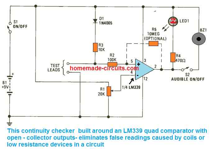
Potentiometer R1 could be a trimmer type variable resistor, in case you intend to make use of the device for continuity tests, R1 must be a multi-turn type for simplicity of adjustment.
The relationship to be examined is placed across the test probes and to ground, and across the junction of R2 and R3.
Parts R3 and D1 safeguard against unintentional application of voltage to the circuit.
Considering that the non-inverting input possesses a high impedance, the intersection of R3 is almost just like the non-inverting input so far as proportions are involved.
Once the voltage at the non-inverting input of U1 at pin 5 drops under that at the inverting input, the output becomes low. This leads to the buzzer becoming active and sounding, showing continuity.
Potentiometer R1 adjusts the limit where the buzzer gets triggered and sounds.
When resistance is detected across the R2 /R3 junction and ground, a voltage divider is created, and this is referenced to the voltage divider established by potentiometer R1.
In case the resistance is very small in comparison to the R1 value adjustment, the buzzer starts making noise.
How to Calibrate
In order to scale and calibrate the tester, you will need a couple of resistors; 100 ohms and 120 ohms. Hook up the 100 ohm resistor across the test probes and start tweaking R1 until the buzzer starts making noise.
Next, hook up the 120 ohm resistor and ensure the buzzer remains perfetly silent. The continuity tester is at this point fixed at examine any resistance below 100 ohms. None of the components values are critical, and neither is the battery voltage because the comparator is configured for voltage ratios only and not specific values.
6) Smart Continuity Tester
The majority of continuity testers currently available are susceptible to false results.
They won't show wrong results intentionally, yet when they find a smallish resistance, they are going to still show you that there's probably a continuity.
The following 6th continuity tester design takes a different approach. In case there is continuity, it is going to inform you about the same.
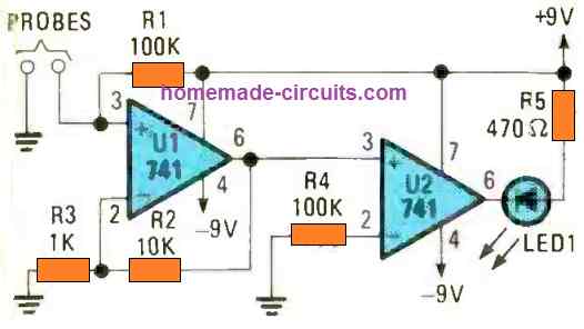
But during a low resistance via an electronic component, the circuit can confirm that too without fail. Referring to the figure above, we find the circuit makes use of a couple of 741 opamps.
It provides a short-circuit test current of lower than 200uA. It picks up resistance values of lower than 10 ohms. Sweetest of all, it will never malfunction when it comes across PN junction or a diode.
7) Simple Audible Continuity Tester Circuit using a Single UJT
Audible continuity checkers are fantastic since you don't have to look at a meter scale, allowing you to concentrate on where you're putting the probes!
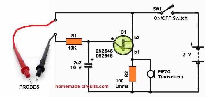
Here, in the 7th design, the UJT is set up as a straightforward oscillator in the audio band, with a piezo transducer serving as the audible output.
Once the black and red probes are attached, the oscillator circuit completes. Q1 oscillates, and the voltage pulses that are generated across R2 drive the piezo transducer, which causes the beep to be heard.
Changing R1 or the value of the 2u2 capacitor will alter the oscillator pitch. You'll see that the output pitch lowers in circuits that are being tested when the resistance is about 1K or higher. This may be helpful!


Questions & Answers
I wanted 5 multiple continuity testers (for a game). Each continuity test needs to be independent. I chose the NE555 circuit and built my testing set to light a LED but didn’t think it through.
I would have liked to run the set on one battery rather than a battery for each separate individual circuits . If a single battery is used for all tester circuits, Each lead pair connects between an output on the NE555 and ground. So any lead from any of the NE555s to ground triggers the LED to be on.
Can you think of a mod that would allow making each circuit independent but still sharing the same power supply.
I think you can try using separate bridge rectifiers for each of the circuits, and then power all those bridge rectifier inputs from a single battery….check with two units first, and see if it actually works out or not…
Can you suggest a bridge rectifier device. Most chip vendors sell in the 100-1000 volt ranges and may not pass a small voltage.
I could make it out of diodes but that is time consuming.
In case you are interested the game is a puzzle, one of which I am making for my daughter. She is keen on escape room puzzles. The idea is to present a set of wires and sockets. Each wire must be connected to the right socket hence the need for an independent continuity tester. The high (or low). outputs are input to a binary “and” chip and if the test passes it open a box with another clue.
Sure, the bridge rectifier can be built using 1N4148 diodes, which will drop 1.2V max at the output…
Your game concept looks great, I am sure your daughter, and other kids will love playing it.
I made a bridge rectifier for each NE555 isolating the positive and negative power supply to be only through a bridge. (very fiddly) Connecting a probe to any of the other NE555 earth’s set off the LED diode. I need it to only toggle in the circuit to which the probe belonged. What does work is a separate 9v battery for each NE555 circuit. A little wasteful with batteries but at least I can get the project to work
Assuming you made the following type of circuit, 5 of these…. operated with a common 9V supply, in that case the output results for each of these circuits will be perfectly independent and and complementing their relevant input probe detections:
https://www.homemade-circuits.com/wp-content/uploads/2026/03/555-continuity-tester-circuit.jpg
Detecting a continuity on one 555 probe just cannot trigger the LED output of the other adjacent 555 circuits….because the outputs of each individual 555 circuit solely depends on its very own pin2 detection.
My goal is to test multiple connections so that there is a connection but it goes to the right place.
One probe will not trigger another circuit’s LED. however the problem is ground. A probe from any of the five circuits will trigger its LED if touched on any of the other circuit’s earths.
This is important for an application that strives to test connections that have been made but also to the right destination.
For example suppose there are only two connection (rather than 5) that we wish to test. A correct connections is A->B and C->D with independent NE555 circuits to test A and C. Suppose an incorrect connection is made A->D, C->B. In that case a test on A should not trigger and LED but it does. A probe to A will trigger the LED because it shares and earth with the C-D connection and also visa versa.
If each circuit is wired with an independent 9v battery it all works.
Thew next step would be to run the LED outputs to a binary comparator testing that all the continuities are “on”. Unfortunately the comparator will have to have an earth that recognises a binary 1 from each NE555 circuits. …..and the problem re-establishes itself.
OK, in that case you can try isolated power supply modules like the B1215S-2W, and also use CMOS version of the 555 like the LMC555 or the 7555.
Hi, Can #6 above accurately test a diode IN CIRCUIT?
Thanks!
Hi, From the description it seems it can do the job, however since I have not tested it practically i cannot confirm the results accurately.
when designing and building your own continuity testers, what results do you get if lets say your previous continuity testers were unable to test electric connections
All the above continuity testers are designed to do the same thing, that is detect a continuity in an electronic or electrical circuit. Some testers may not be too accurate and may read low resistances as a continuity, whereas others may be more accurate and may be able to differentiate between a low resistance and continuity….
so how would you conclude about continuity testers
Continuity tester circuit can be used to check for a continuity in circuits, which can be through jumpers, diodes, transistors, inductors etc.
I think another way to say this is that the tester I have in mind would allow a sender to be in series with another wire which is in series with the remote LED indicator/beeper unit which is in series with a return wire back to the sender (which has the battery). A commercial version exists, but it is annoying to purchase repeatedly because it has no fuse protection against outside overvoltage (eg 12V or 120V external voltage) when accidentally connected to live circuit.
I agree, this can be perhaps prevented through a high wattage series resistor.
Thanks for these clear Circuit Tester circuits.
Special request: Can you please add a schematic for incorporating two additional features:
1) A remote indicator that prove not only continuity from point A to point B, but also that the circuit electricity is going thru point C and point D at the other end of two wires (for example). This feature is invaluable in testing long circuits with only one person. Buzzer/LED or both. Red or Green for normal or crossed polarity.
2) Even more important is a way to test for any voltage on the circuit and temporarily disable the tester if there is 12V or 120V live current on what you thought was turned off.
There appears to be no commercial product with these features and it would be fantastic to be able to build one better than commercially available.
Glad you liked the circuits, however which points are C and D that you are referring to? I cannot see any C and D points in the diagrams?
2) I don’t think the above circuits must be used with any wires that may be associated with some voltage source…the ideas are specifically for wires that are completely isolated from a voltage source.
Sorry, the Point C and Point D were hypothetical and not shown in any of your diagrams. What I meant was something like the Southwire 40040S which has to parts:
1) A 9V battery powered ‘sender’ with two alligator tip leads to connect to a couple of wires at one end of a vehicle for example. Sender has LED’s to signal connection. They light up and beeps if the two leads on the sender are connected directly together.
2) A Remote section, also with two alligator clip leads that connect to the other ends of the same two wires in #1 above, but too far away for one person to be both places. So you connect the remote two leads on the far-away ends of the two wires, and if they complete a circuit, both sender (#1) and remote (#2) light up and beep. Green if black to black, red to red, and Red if reversed polarity.
In brief, I’m looking for away to check continuity of two different wires at the same time AND verify that the continuity is not from a short-to-ground on the vehicle somewhere between the near and far ends of the two wires.
The remote is basically an LED / Beeper unit that allows the main sender (powered by 9V battery) to verify that its power is going all the way to the end and back. If there is a short-to-chassis-ground somewhere in between, the sender will light and beep, but the remote unit LED will obviously not see any power because the electricity is taking a ‘shortcut’ and so the remote LED’s wont light.
The commercial version mentioned above is very useful for a one-man circuit testing team! BUT it has a real problem because if you ever forget and connect it to a live 12V circuit, the remote LED’s blow instantly and the $30.00 device is garbage! 🙁
I wish I could upload a schematic to make this clearer but please feel free to ask more if you this doesn’t make sense. I wish I knew how to build something like this with a fuse or circuit breaker to protect against both 12V and 120V (or 240V?) accidental voltage.
Thank you for the detailed explanation… I understood the working and also confirmed the same through a relevant video. However the functioning looks quite tricky, and I am unable to figure out a circuit with the exact specifications.
In my design the sender will always illuminate a green LED for continuity. If the polarity does not match between the sender and the remote unit, then the sender will illuminate green LED, and the remote unit will illuminate red LED. If the polarity matches then both the sender and the remote will illuminate greens LEDs.
The flashing thing can be included in the design, but again the specs will be slightly different. In my design both the units will flash their LEDs together.
The above design is actually extremely simple and I think it fulfills the basic requirement as specified by you.
The high voltage could be avoided through a series resistor or a capacitor
Let me know if you would want to see this design.
YES! I would very much like to see your design.
For the record, the flashing adds no useful functionality and your local green, remote red solution is elegant.
What might add functionality is the resister you mentioned to protect against 12V, 120V, or 250V accidental connection (if that works). A competitor of the product I mentioned states it has a “250V, 0.5A fast blow fuse” to protect it, but it is not clear whether that fuse protects both sender and remote, or just the sender. Since I seem to blow the remote just as often as the sender, both would need to have fuses. That specification only seems to come in the cylindrical glass fuse holder form factor rather than the more modern and easier to change ATC (Automotive) style. But that’s OK if it works. Do you think such a fuse placed in series of one of the leads of both sender and remote on your proposed schematic? Or would a resistor be better.
Either way, I am anxious to see your design. To make it completely block buster, it must have enough internal voltage power supply to test circuits many meters long, but not so high as to blow sensitive automotive ECM/ECU units or ICs.
I and many other people I suspect would find your design useful. And if you ever make such a testing unit commercially available I would purchase it if it is guaranteed not to blow when accidentally connected to a live circuit.
I don’t think any kind of fuse will help, since it might take just a few milliseconds for the LEDs to burn if subjected to an unprotected high voltage.
Here’s the design that I propose, with complete accidental over voltage protection:
Let me know if you have any problems understanding the circuit.
Many thanks for sharing this. If it works as described, a fantastic improvement over commercially available circuit testers. The schematic looks very clean and elegant, although because I am not an electrical engineer I make no claims to understanding the logic behind it, before I make a Digi-key order, I do have a couple of questions if I can presume to further request:
1) Is C3 100 nanoF? (the ‘n’ a bit hard to read)
2) Why is capacitor C2 white & black (compare C3) I’m presuming this is a schematic software issue but perhaps there is something I’m overlooking (25V?)
3) Does C3 have any special voltage requirement (all other C’s have documented voltage). Presume 25V OK by analogy to C2 and 9V source, but not sure if C3 serves as part of the protective accidental overvoltage protection function.
Thanks!
You are welcome! Here are the answers to your questions:
1) C3 is 100 nano Farad that is equal to 0.1uF (ceramic disc)
2) C2 is supposed to be a common electrolytic capacitor which is polarized, the white side indicates the positive pin of the capacitor
3) C3 is a ceramic disc type capacitor which are rated at 50 V by default.
The remote circuit can be assumed to be fully protected, however I am not sure about the sender circuit. I think a series diode can make it more robust, here’s a revised diagram for the same:
Wow! Thank you! Glad I asked about the polarized capacitor.
Very much appreciate your input and I will do my best to turn this into a very useful personal test tool. I think this makes a total of 6 circuits for this page now! I’m going to stop asking before you’ve designed it into a self driving car or something. Now to order a few parts. Thanks! 😉
Sure, No problem at all, please feel free to ask further questions if you have any, and let us know if the circuit doesn’t work as required.
The RED LED at the sender’s side is not required and can be removed
And a 4th question:
4) Will the 0.47 uF 400V capacitors protect against AC overvoltage, or only DC?
I don’t plan to use it around any 120V AC circuits, but in rare cases it might and I’m not sure how this circuit would protect against this.
The 0.47uF/400V is supposed to limit the current to 20 mA ensuring no excess current can enter regardless of the input voltage, and regardless of whether it is AC or DC.
I want to build the continuity tester using arduino and relay, how to proceed in this
Hello sir,
I am looking to make a continuity detection for a terminal block and to alert the user when something was completely connected. I have attempted using the circuit in another article where I think you have commented with two transistors and resistors. But it took a while between when continuity is detected and when is not detected as it was a 12-9 volt source for the terminal block and it is also controlled by a MOSFET. I am looking at a solution and was wondering if a voltage divider were the LED is supposed to be that goes to the analog pin would be able to detect continuity as soon as it is connected and as soon as it is removed.
Here is the link to the other article (the schematic I am referring to is the last one with two transistors and resistors): https://www.brighthubengineering.com/diy-electronics-devices/67224-build-yourself-a-simple-continuity-tester/
Thanks for your help.
Hello Navid, yes probably this can be solved with a resistive divider and an LED, but will require a supply to be fed to the terminal block through a resistor. When this voltage gets grounded via the continuity, the LED lights up
Would this work as well if the voltage would be going to an analog pin to be read as that is the goal of the circuit? Thanks for the help.
That can be difficult to conform without checking the schematic on the other side
I can replace BC557 transistor into another PNP transistor
and BC547 other NPN
yes that’s possible
Hi thanks for ur post. What s the voltage of cap 0.1uf
Thanks Aariz, it's 50V
This circuit is really sensitive. I replaced the led with a buzzer. It even works across a 1M resistor. Can this circuit be adjusted to only buzz when resistance is of the trace to test for continuity is less than 100 ohm?
the LED can be replaced with a a buzzer for getting an audible indication
yes that's a valid point, to solve this you can try adding a 10k or a 100k preset whichever suits better across the base and emitter of the BC547 transistor, or parallel with the 0.1uF capacitor….then you can adjust it appropriately for acquiring the desired amount of sensitivity.
How do we reduce the sensitivity of this circuit? is it by changing the 1M resistor to a lower value?
you can add a 1M pot parallel to the 0.1uF cap and use it for setting the sensitivity level.