In this article we are going to see how to build a home security system circuit using arduino which might save your home from intruders one day.
Housebreaking happens every few seconds in the world. By the time you read this sentence, crooks already broke into someone’s house.
A golden rule: Prevention is better than cure, it is always better to prevent the crooks by deterring them (in any form such as loud alarm) than to log a complaint in police station aftermath the incident.
The PIR Sensor
The brain and heart of the project is arduino and PIR sensor respectively. The PIR sensor senses the motion of object which emits infra red waves such as human or animal.
It detects any thing comes into its range and also detects anything gone out of its range. The PIR sensor is very sensitive to tiny changes; even small a moment by a human or an animal can detect changes and gives out the signal, but it can guaranty that it never gives false alarm.
The PIR sensor gives out 3.3V active high signal when motion is detected for pre-set period. This active high signal is fed to arduino which decides what to do next.
The Circuit Layout:
This Arduino home security project can be build from junk box parts, which holds some I/Os for the user.
Use your creativity for layout design so that it looks good and neat.
The PIR sensor should expose outside, all the buttons also placed outside for easy access. Make sure cutout for main siren should adequately open so that alarm don’t get muffled, or place whole siren outside the junk box as shown in picture.
Make sure the whole system is well placed on the wall and must not fall out easily. You may drill or use double sided tape in combination with super glue to stick with wall, if your junk box doesn’t have indent for nailing. Use “arduino pro mini” if your junk box is small.
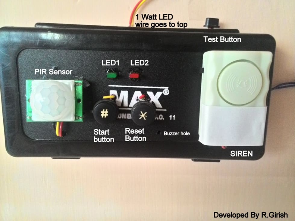
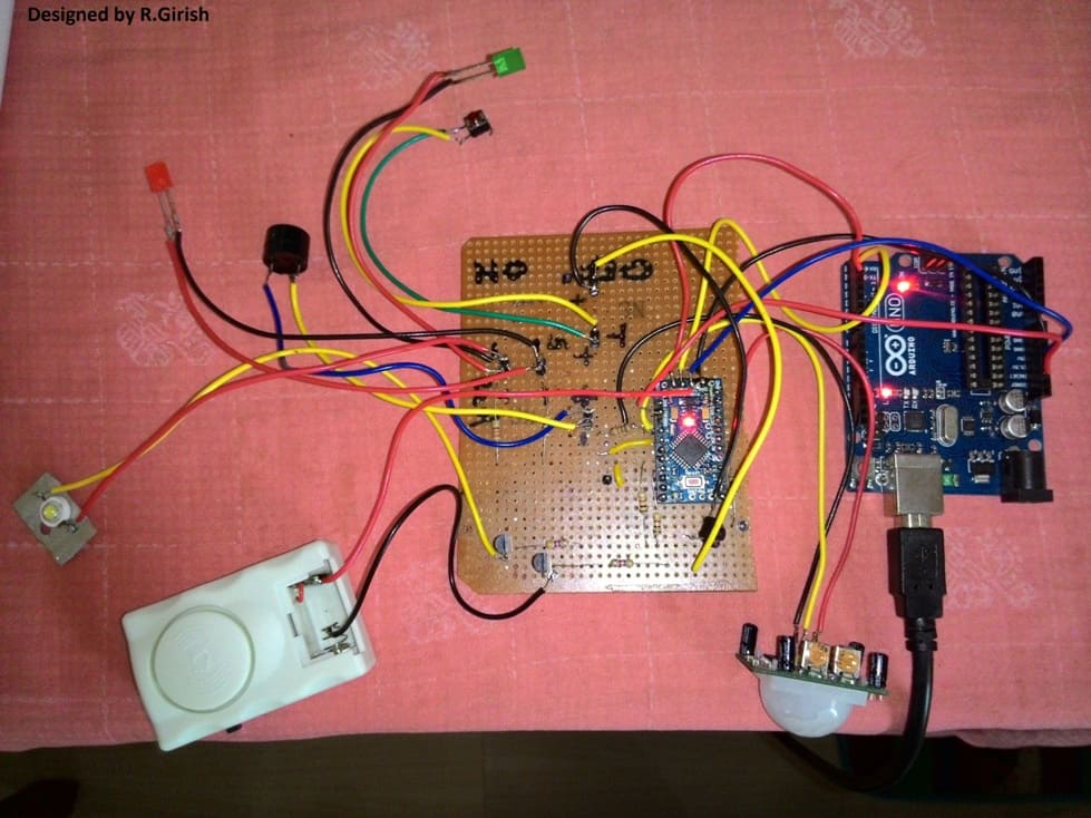
Here is author’s prototype:
In this prototype I’ve used pencil box for the whole setup, one 1 watt white led is fixed on the ceiling for intruder alert lighting.
This 1watt LED lights up small area reasonably bright during dark situations which might deter the intruder. Make an onboard UPS system for this project within the junk box, so that it will be active even during power failure.
The Design:
The whole project is build based on arduino pro mini, but you can do the same with your favorite arduino board.
Note: Try not to modify anything given in the schematic if you are newbie to arduino. If you do so, change the code appropriately to your modification.
Program Code:
//---------Program Starts--------//

//----------Developed by R.Girish------//

int input=2;

int alarm=3;

int buzzer=4;

int start=5;

int test=6;

int led=7;

int green=8;

int red=9;

void setup ()

{

pinMode(input,INPUT);

pinMode(alarm,OUTPUT);

pinMode(buzzer,OUTPUT);

pinMode(start,INPUT);

pinMode(test,INPUT);

pinMode(led,OUTPUT);

pinMode(green,OUTPUT);

pinMode(red,OUTPUT);

}

void loop ()

{

digitalWrite(alarm,1);

digitalWrite(green,0);

digitalWrite(led,1);

digitalWrite(buzzer,1);

delay(250);

digitalWrite(buzzer,0);

inactive:

if(digitalRead(test)==1)

{

digitalWrite(green,1);

digitalWrite(buzzer,1);

delay(250);

digitalWrite(buzzer,0);

delay(10000); // Test delay

digitalWrite(buzzer,1);

delay(250);

digitalWrite(buzzer,0);

trig:

if(digitalRead(input)==1)

{

digitalWrite(led,0);

digitalWrite(buzzer,1);

digitalWrite(red,1);

delay(2000);

digitalWrite(buzzer,0);

digitalWrite(led,1);

digitalWrite(green,0);

digitalWrite(red,0);

}

else

{

delay(1);

goto trig;

}

}

if(digitalRead(start)==1)

{

digitalWrite(green,1);

digitalWrite(buzzer,1);

delay(100);

digitalWrite(buzzer,0);

delay(100);

digitalWrite(buzzer,1);

delay(100);

digitalWrite(buzzer,0);

delay(20000);

delay(20000);

delay(20000);

delay(20000);

delay(20000);

delay(20000);

digitalWrite(buzzer,1);

delay(100);

digitalWrite(buzzer,0);

delay(100);

digitalWrite(buzzer,1);

delay(100);

digitalWrite(buzzer,0);

active:

if(digitalRead(input)==1)

{

digitalWrite(led,0);

digitalWrite(red,1);

delay(20000);

digitalWrite(alarm,0);

digitalWrite(buzzer,1);

delay(10000);

delay(10000);

delay(10000);

delay(10000);

delay(10000);

delay(10000);

digitalWrite(alarm,1);

digitalWrite(led,1);

digitalWrite(buzzer,0);

delay(1);

goto active;

}

else

{

delay(1);

goto active;

}

}

delay(10);

goto inactive;

}

//----------Developed by R.Girish------//

//---------Program Ends---------//
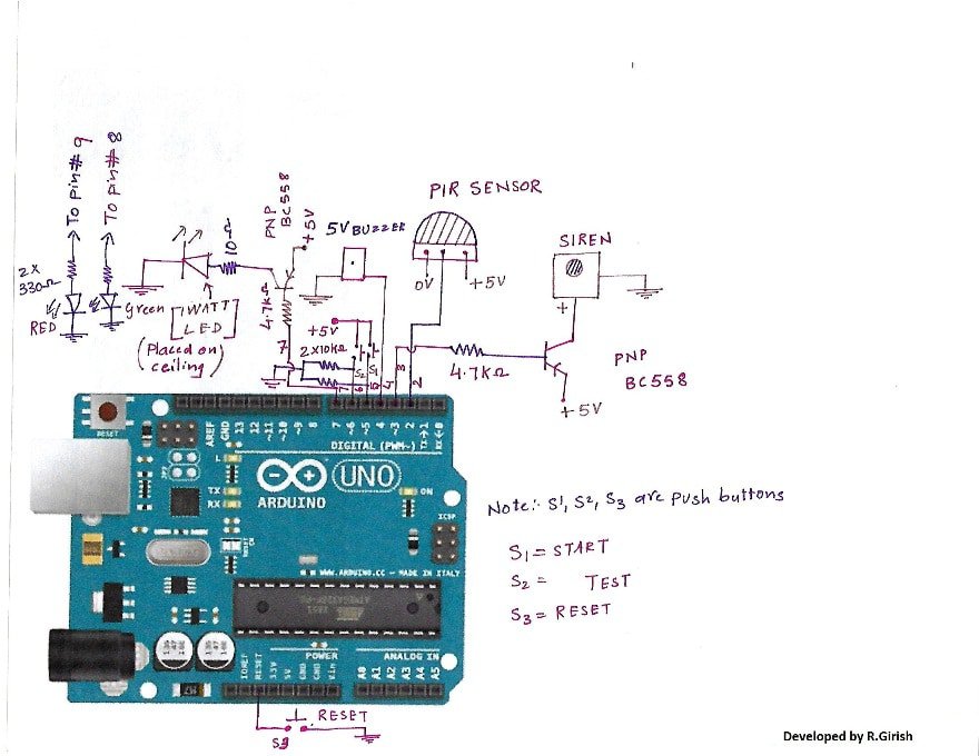
The home security system circuit using Arduino Uno is shown above, but you can use any of the arduino boards.
The circuit may look complicated but, actually not. R3 is reset button is connected to Reset pin of the arduino and grounded.
All the transistors are PNP type. If you want use NPN transistor, do the appropriate changes in the code. There is 5v buzzer to give audio feed back to the user when any button is pressed.
Note: A pull down resistor 10K must be connected to #Pin 2 of the arduino, which is not shown in the schematic.
Direction for testing:
After completing the build and upload of the code, do the following instruction for testing.
· Power the circuit and press “test” button; you will hear a beep and green LED on, indicating the circuit is ready for test mode and go away immediately from the circuit. After 10 second you’ll here another beep, signifying the setup is ready to detect motion.
· Come near to the PIR sensor, immediately you will hear beep for 2 second along with 1 watt led ON. Then it goes to idle state.
· If the above following instruction works, your security system is ready for use. Do frequent testing to prolong working span of the system.
Direction for use: Understand the following instructions carefully.
· Lock the doors and press “Start button” when gives double beep indicating you may leave now. After 2 minutes it will give another double beep (by the time you won’t be present at home) indicating the system is active and ready to detect motion.
· If any motion is triggered by the intruder, firstly the 1 watt white led lights up and red LED also turns ON. This is first stage to deter the crook. The intruder may think someone is still left in the home.
· After 20 seconds the alarm starts, this is second stage for deter the crook. The alarm will pull the attention of many near the area.
· After 1 minute the alarm stops 1 watt LED turns OFF but RED led stays on, indicating someone triggered the system.
· When owner of the house returns he will trigger the system, but it gives 20 second to deactivate the system by pressing “Reset”. By doing so it will go to idle mode. If it was a crook he/she don’t know the presence of security system and alarm triggered after 20 seconds.
Where to place the Arduino security system:
When you build this or buy similar stuff from market, don’t tell anyone about it. Telling to someone may alert the crook and may try to bypass it.
· If you are living in apartment, place it inside the room near the door. Placing outside the door when there is a common way for going many people, may trigger false alarm because it could be your neighbor.
· If you are living in house with compound, place it outside the door. If someone tries to jump the compound wall the alarm gets triggered.
· If you have pets try to keep them away from security system. They will trigger false alarm.
· Always use your imaginations and predictions for placing the security system.


Questions & Answers
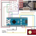
can more than one Pir sensor be used
may be yes, by using isolating diodes 1N4148 with each PIR output