In this article I will show how to construct a GSM fire alert circuit system using Arduino and DHT11 sensor, which will alert the user via text message (SMS), regarding a fire hazard within the premise where it is installed.
Using DHT11 Sensor
We are using DHT11 sensor for sensing unusual temperature rise around the local area. We can precisely set the threshold temperature in the program, if the temperature rises above preset threshold, the GSM modem starts sending alert SMS to the recipient.
How it Works
The GSM fire alert circuit setup consists of 3 parts, the sensor, Arduino which is the brain of the project and GSM modem which sends SMS alert.
The wiring of the setup is same as other GSM based projects which was discussed in this website. The only difference is the addition of DHT11 sensor to Arduino.
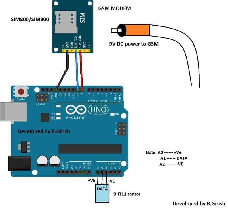
The TX of GSM is connected to pin #9 of Arduino and RX of the GSM is connected to pin #8 of Arduino and ground to ground connection is also connected. The power and data connection of the sensor is optimized for reduced wiring congestion while prototyping.
Please note the connections carefully and insert the sensor from A0 to A2 in correct orientation as illustrated below.
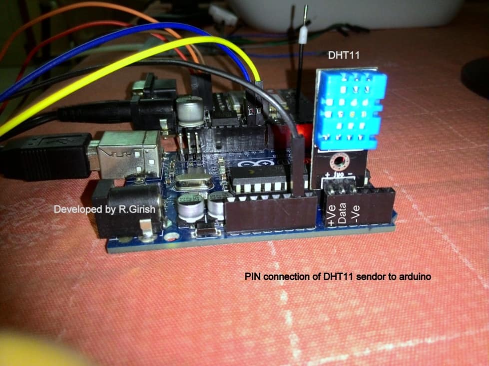
Reversing the orientation of the sensor will give out “NO DATA” on the serial monitor. If reverse orientation is kept for prolonged period it may even damage the sensor. So, be cautious about the sensor connection.
Here is a completed author’s prototype:
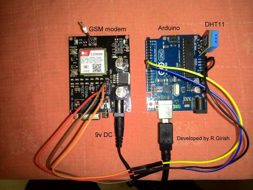
Always power the GSM modem with external power supply. A 9V 500mA power adapter will be enough for GSM modem. The serial monitor is not mandatory for this project as it is going to be a standalone project. We need serial monitor only while testing the prototype.
Make a DC UPS system, schematics is available in this website and try to make the power button easily accessible outside the chassis of your project, so that GSM modem can be powered ON after a brief power failure.
The external power button can be made by soldering wires from pins of the power button on the GSM modem. DC UPS will reduce necessity to power ON the GSM modem after every power failure. It gives plug and forget kind of feature. Now let’s see how the whole setup functions.
In case of fire the room temperature rises rapidly in short period, the sensor has the ability to measure form 0 to 50 degree Celsius.
When the temperature rises above the preset threshold value in the program (within 0 to 50) it sends SMS alert saying “Fire alert: 45.00 degree Celsius”. 45 degree Celsius is the temperature of the room during sending SMS; the temperature would reach beyond 100 degree Celsius within minutes after fire accident. Two SMS alert is send for redundancy, in case if the one of the sent message is failed.
If the sensor failed or the sensor gets disconnected from Arduino, the information is send to the user via SMS twice saying “No data from sensor/sensor disconnected“
The program comes to halt for 30 minutes after sending SMS alert for fire or sensor disconnection. It checks again for abnormality in room temperature and sensor wire connection after 30 minutes, if any exist, it sending SMS alert again and waits for another 30 minutes.
When the whole setup is completed and powered ON, the GSM modem sends test SMS saying “This is a test SMS from GSM modem” if you receive this message to the recipient number, it means your project is working fine.
Program:
//--------------Program developed by R.Girish---------------//

#include <dht.h>

#include <SoftwareSerial.h>

SoftwareSerial gsm(9,8);

#define DHTxxPIN A1

dht DHT;

int p = A0;

int n = A2;

int ack;

int msgsend=0;

int th=45; //set threshold temperature

unsigned long A = 1000L;

unsigned long B = A * 60;

unsigned long C = B * 30 ;

void setup()

{

Serial.begin(9600);

gsm.begin(9600);

pinMode(p,OUTPUT);

pinMode(n,OUTPUT);

digitalWrite(p,1);

digitalWrite(n,0);

gsm.println("AT+CMGF=1");

delay(1000);

gsm.println("AT+CMGS="+91xxxxxxxxxx"r"); // Replace x with mobile number

delay(1000);

gsm.println("This is a test SMS from GSM modem");// The SMS text you want to send

delay(100);

gsm.println((char)26); // ASCII code of CTRL+Z

delay(1000);

}

void loop()

{

top:

msgsend=0;

ack=0;

int chk = DHT.read11(DHTxxPIN);

switch (chk)

{

case DHTLIB_ERROR_CONNECT:

ack=1;

break;

}

if(ack==0)

{

Serial.print("Temperature(°C) = ");

Serial.println(DHT.temperature);

Serial.print("Humidity(%) = ");

Serial.println(DHT.humidity);

Serial.println("n");

delay(2000);

}

if(ack==1)

{

goagain:

msgsend=msgsend+1;

Serial.print("NO DATA");

Serial.print("nn");

Serial.println("Sending SMS......n");

delay(500);

gsm.println("AT+CMGF=1");

delay(1000);

gsm.println("AT+CMGS="+91xxxxxxxxxx"r"); // Replace x with mobile number

delay(1000);

gsm.println("No data from sensor/Sensor disconnected");// The SMS text you want to send

delay(100);

gsm.println((char)26); // ASCII code of CTRL+Z

delay(1000);

Serial.println("Message is sentn");

if(msgsend==2)

{

delay(C);

goto top;

}

else

{

delay(10000);

goto goagain;

}

}

if(DHT.temperature>=th)

{

doagain:

msgsend=msgsend+1;

Serial.println("Sending SMS......n");

gsm.println("AT+CMGF=1");

delay(1000);

gsm.println("AT+CMGS="+91xxxxxxxxx"r"); // Replace x with mobile number

delay(1000);

gsm.println("Fire Alert:");// The SMS text you want to send

gsm.print(DHT.temperature);

gsm.print(" degree celsius");

delay(100);

gsm.println((char)26); // ASCII code of CTRL+Z

delay(1000);

Serial.println("Message is sentn");

if(msgsend==2)

{

delay(C);

goto top;

}

else

{

delay(10000);

goto doagain;

}

}

}

//--------------Program developed by R.Girish---------------//
Note: You have to place the recipient number in 3 places in program which is described in the program as
("AT+CMGS="+91xxxxxxxxx"r"); // Replace x with mobile number
• Set the threshold temperature
int th=45; //set threshold temperature
The threshold temperature must be set high, greater than usual temperature fluctuation of the room .For example: DHT11 has maximum measuring capacity of 50 degree Celsius, so threshold temperature can be set from 45 to 47. High threshold value is set so that it won’t send false triggered SMS alert for small changes in room temperature.
If you have further doubts or quesries regarding the discussed GSM fire SMS alert circuit system, please do not hesitate to put them forth through your valuable comments.


Questions & Answers
pls I wnt to embarked on this project and I needed the circuit diagram as it is not showing here. My mail for help. mustaphataiye@gmail.com
It may be the problem from your Internet service provider, try using a proxy server to access the website, and see if that helps…
excellent project. He sends me an error. This is the error that marks me.
exit status 1
expected ‘)’ before string constant
Thank you, please check it now, I have corrected the following line
\”+91xxxxxxxxxx\”\r”
The slash near “r” had strangely dissappeared, I have put it now.
good work sir,can you help me design a 8 relay circuit, controlled by a (sim800l) with the help of my android phone . turnning each relay off and on at will with am sms message.
thanks Lexcop, if possible we will try to update it for you!
sir, we are getting a error in the dht library that is #include
Sir, need your help.. how can I contact you?
Hi rahul, you need to add the library in you Arduino IDE. only then your program gets compiled.
you can download from here: https://arduino-info.wikispaces.com/file/detail/DHT-lib.zip
Sir, during the compilation of the program, am getting a error
Pls can you make this same. Circuit only not with a fire alarm but a door alarm.thank you..
I know it is not free energy….. I mean free of cost…. thanks sir…
sir, today I observed a very interesting thing…I connected a LED bulb's ( ) point to TV cable and (-) to Earth….. the LED was on but not so brightly…one more thing change of ( ),(-) dose not matter here… I think you can help me with a simple circuit to amplify the voltage…. it will be a free energy source for me…….* here TV cable means the cable which is coming from broadcast not the part that is connected to TV… I mean no need to on TV ….thanks sir.
you can find the library from this link : https://arduino-info.wikispaces.com/file/detail/DHT-lib.zip
SIR PLEASE SEND ME UR DHT LIBRARY FOR THE GSM Fire SMS Alert Circuit using Arduino. I FIND HARD TIME TO FINISH THIS PROJECT. PLEASE SEND IT TO double.jg.adz@gmail.com. thank you
Soumen, it is not free energy, you are using the video signal voltage for the LED illumination…it cannot be amplified.