In this post I have explained an electronic engine speed governor or controller circuit using an RPM feedback signal loop through a hall effect sensor network. The idea was requested by Mr. Imsa Naga.
Circuit Objectives and Requirements
- Thank you very much for your time. I believe this circuit would be suitable for a single phase supply. My alternator is 3 phase 7KvA and I would like to couple it with a diesel vehicle engine having an accelerator in lieu of a speed governor.
- What I would like to implement is - An "ELECTRONIC ENGINE SPEED GOVERNOR" which would probably have an electronic servo controlled mechanism such as- A Speed Sensor circuit(Engine RPM sensor) to drive a servo motor to actuate the accelerator mechanism in order to maintain a constant speed of the engine with respect to the load applied to the alternator.
- This would help in retaining the frequency as well as the voltage of the generator. I would be able to take care of the mechanical aspect, if you kindly design a circuit to control the Servo motor in such a way that it can be turned to either direction with respect to the change in the engine RPM. Thank you very much in Anticipation.
Circuit Diagram
The Design
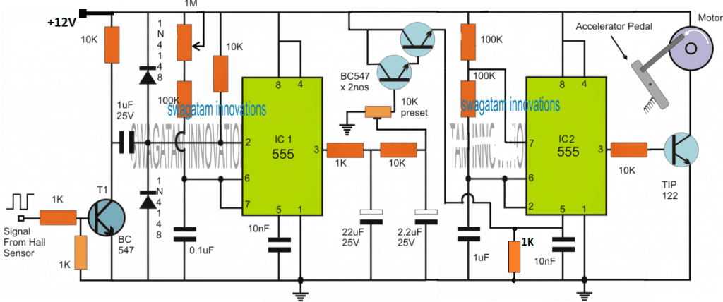
The circuit of a diesel engine speed governor or controller can be seen in the above figure using a feedback RPM processor or a tachometer circuit
The left side IC1 555 stage forms a simple tachometer circuit which is configured with a Hall effect sensor attached with the engine's load wheel for sensing its RPM rate.
The RPM is converted into a proportionately varying pulse rate or frequency and is applied at the base of a BJT for toggling the pin#2 of the IC1.
Circuit Operation
IC1 is basically rigged in the monostable mode which causes its output to generate a proportionately adjusting ON/OFF switching, whose period is set using the shown 1M pot.
The output from IC1 which carries the the RPM content in the form extended timed pulses is adequately smoothed by an integrator stage consisting of a couple of RC components using resistor 1K, 10K and 22uF. 2.2uF capacitors.
This stage converts the monostable's rough RPM data into a reasonably smoothly varying or exponentially varying voltage.
This exponentially varying voltage can be seen connected with pin#5 of the next IC2 555 stage configured as an astable circuit.
The function of this astable is to generate a very narrow or low PWM output at its pin#3 in its normal operating conditions.
Here normal operating condition refers to the situation when the sensed RPM is within the specified limit and pin#5 of IC2 is not getting any voltage input from the emitter follower. This low PWM output can be implemented by suitably adjusting the two 100k resistors and the 1uF capacitor associated with IC2 pin#6/2 and pin#7.
This low PWM from pin#3 of IC2 is unable to switch the TIP122 sufficiently hard and therefore the indicated motor wheel assembly is unable to get the required momentum and therefore stays deactivated.
However as the RPM begins rising the tachometer begins producing an exponentially higher voltages which in turn causes a proportionately increasing voltage at pin#5 of IC2.
This subsequently allows the TIP122 to conduct harder, and the connected motor to gain sufficient torque, so that it begins pressing the attached accelerator pedal towards decelerating mode.
This procedure forces the diesel engine to reduce its speed, which correspondingly causes the tachometer and the PWM stages to restore to their original conditions, and enforcing the required controlled speed for the diesel motor.
Instead of the shown accelerator motor arrangement, the collector of TIP122 could be alternatively wired with the CDI unit of the diesel engine for an identical speed reduction, for facilitating a solid state and more reliable implementation of the discussed electronic engine speed control or electronic engine speed governor circuit.
How to Set Up
Initially keep the IC1, IC2 stages disconnected by removing the emitter follower link with pin#5 of IC2.
Next make sure that the two 100k resistors are appropriately changed and adjusted such that pin#3 of IC2 generates the narrowest possible PWMs (@ approximately 5% ON time rate).
After this, using a 0 to 12V adjustable power supply, apply a varying voltage at pin#5 of IC2 and confirm a proportionately increasing PWM at pin#3.
Once the astable section is tested, its the tachometer must be checked by applying a known RPM pulses corresponding to the desired over-limit RPM. During the adjust the emitter follower BJT base preset such that its emitter is able to generate at least 10V or a level enough to cause the IC2 PWM produce the required torque on the connected pedal control motor.
After some further tweaking and experimentation you can expect to achieve the required automatic speed control for the engine and load connected with it.
UPDATE
If the motor is replaced with a spring loaded solenoid, then the above design could be much simplified as given below:
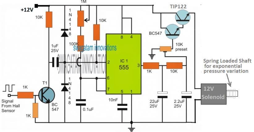
The solenoid shaft could be coupled with the accelerator pedal for accomplishing the intended automatic engine speed regulation.
For more options regarding frequency to voltage converter, you can refer to the this article.


Questions & Answers
Hello Swagatam.
this is an interesting circuit I have a diesel generator with electric controlled governor i need a controller for looks like this could work except I need the output voltage to work opposite, as frequency goes up it needs the output voltage to go down so I can set it to hold 60hz, Approximately 1v into the governor. Can this circuit be modified to do this ? I do have a freq to voltage board but it’s output follows the frequency the opposite also, freq up voltage up…
Thank you Dave,
I think that’s possible.
To invert the output response we just have to replace the TIP122 with a PNP TIP127 transistor. A PNP instead of an NPN will simply invert the output PWM response.
Thank you. I figured it was something simple i was missing.
Do i need to change anything else in the circuit, or just swap out the tip122 for the tip127 ?
Only the TIP122 will need to be replaced with a PNP TIP127 for producing a reversed PWM output response. Everything else can remain as is.
Let me know you face any issues with the circuit.
awesome ! thank you is that the same for both circuits shown ? tried it on sim programs but they didn’t have the 122 or the 127 so it didn’t work. if I use the f/v converter I have that puts out dc v that follow the freq. without pulse. can i just add the Tip127 as in the update circuit to flip the output ?
Yes, both the designs can be used with TIP127 PNP output transistors for a getting an inverted response on the load.
You can use any F to V converter with a PNP TIP127 output transistor for reversing the output.
However, if the output from the converter is an analogue signal and not a PWM then the TIP127 might get hot and might need a heatsink.
Hello. Cane I make the Electronic Engine Speed Governor Circuit control my eddy current dyno that has a load controled by Semikron SKPC200 THAT REQUIRES A 0-5VOLT INPUT ?
Hello, for eddy current based motor torque control, you can implement the following concept:
Constant Torque Motor Speed Controller Circuit
Hello Swagatam
Very nice project. I need little more help from you in reproducing this project
Thank you Selvan, you can feel free to ask your questions here I’ll try to solve them
Hello . I wish to fit this to my eddy current dyno to keep the rotation speed constant.The voltage output will be used to control a control box. How do I set the speed to keep it at.? Will just powering module when I have the rpm desired set the rpm needed ?
Regards Zane
Hello, firstly, you will need to integrate the dynamo wheel with a hall effect and magnet system, whose response will need to be fed back to the IC 555 input. The speed setting can be implemented by appropriately adjusting the 1M preset and the 10k preset.
Hello GR,
Thanks for giving me time. I am eagerly waiting for the circuit.
Thanks & regards
S.Das
Thank you, this was so helpful. I am working on electrical vehicle project using BLDC motor from scratch. I want a speed controller circuit which is simple but also reliable. Do you have any suggestion for me to start with?
Thank you
Hello, thank you, I have already replied to the same question which was also asked under this link
https://www.homemade-circuits.com/2014/12/simple-3-phase-brushless-bldc-motor.html?showComment=1490620694323#c8342805539152093995
Hi GR,
Thanks for reply. I didn't develop any circuit or code. I learnt it from a youtube tutorial.
They uses Arduino Nano V3.0 Atmega328, IR sensor, 16×2 LCD, 100k Trimpot etc. Connection as follows:
LCD PIN / Arduino Nano Pin
RS / D12
E / D11
D4 / D6
D5 / D5
D6 / D4
D7 / D3
D2 pin of Arduini board used for IR signal
VEE pin of LCD board used with 100K Trimpot to control LCD contrast.
Code used as follows:
#include
LiquidCrystal lcd(12,11,6,5,4,3);
float value=0;
float rev=0;
int rpm;
int oldtime=0;
int time;
void isr() //interrupt service routine
{
rev++;
}
void setup()
{
lcd.begin(16,2); //initialize LCD
attachInterrupt(0,isr,RISING); //attaching the interrupt
}
void loop()
{
delay(1000);
detachInterrupt(0); //detaches the interrupt
time=millis()-oldtime; //finds the time
rpm=(rev/time)*60000; //calculates rpm
oldtime=millis(); //saves the current time
rev=0;
lcd.clear();
lcd.setCursor(0,0);
lcd.print("___TACHOMETER___");
lcd.setCursor(0,1);
lcd.print( rpm);
lcd.print(" RPM");
lcd.print(" ");
attachInterrupt(0,isr,RISING);
}
Link: https://www.youtube.com/watch?v=gVl4B7NDnQY
Title: How to make Arduino Based Digital Tachometer By Mr. Innovative
Maximum RPM of M/C is 3500.
Thanks & regards
S.Das
Hi das,
I am on a tight schedule at my college right now . Once I am free I will start producing articles , thanks for you patience.
Regards
Hello GR,
Please design the circuit of steam engine speed controller on the basis of Arduino UNO board.
Thanks & regards
Hi das!
Thank you for the data,I will try to design one soon.
Regards
Hello Swagatam,
Thanks for your time, I am waiting for the circuit.
Thanks & regards
S.Das
Hello Swagatam
Very nice project. I need little more help from you. Please design a circuit with details components list and specification (like: Servo sepc., Arduino board type etc)as mentioned below.
I already made a tachometer using IR sensor , Arduino nano Atmega328 V3.0 and LCD. Now I want to control the speed of engine using servo which will get data from speed sensor & maintain set speed and (if possible)there should be a provision for put the set speed (which will be seen in LCD screen)through key pad.
Please mention total required components details and specification and codes required (if any, i.e: like Arduino code).
Thanks & regards
S.Das
Hi das,
Yes it is possible with arduino.
Can you please explain the method how did you use IR to find RPM.
If possible please give a link to your schematic and code which you have developed. So that I can modify them appropriately to your needs with the same hardware you have.
And please mention the Max RPM of your engine.
Regards
Thanks Das, I'll probably discuss this with Mr.GR who is an Arduino expert and see if has a solution for this.
Hello Swagatam,
Thanks for quick response, if the "provision for giving the set speed (which will be seen in LCD screen)through key pad" will making the circuit critical then leave it and design a circuit of electronics governor with Arduino Nano or UNO board, Servo, IR sensor and LCD screen (which will show the actual rpm) for maintaining pre-defined constant speed. Please describe the project (with Arduino code) in simple steps because I don't have much knowledge of electronics circuit.
Thanks & regards
S.Das
Thanks very much Das, I'll surely try to get the required data and present it here, however since so far I haven't been able to gain expertise in the field of MCU due to lack of time, I would not be able to do it myself, nevertheless will keep looking for it and update it soon, if possible.
Wow… that was real Fast! you had everything in you Box! Only my eyes did not recognize them…..
Thank you very much indeed ! I will need time to digest the circuit despite your clear explanation. I will surely send my feedback provided I don't commit any mistakes in the circuit wiring!
Thanks again for enlightening a blind Netizen…
Kind regards.
Imsa Naga
You are most welcome Imsa…wish you all the best!!