• Skip to main content
  • Skip to primary sidebar

Homemade Circuit Projects

Get free circuit help 24/7

New Projects | Privacy Policy | About us | Contact | Disclaimer | Copyright | Videos | Circuits for Beginners | Basic Circuits | Hobby Projects | Transistor Circuits | LED Drivers 

You are here: Home / Motor Controller / Water/Coffee Dispenser Motor Circuit

Water/Coffee Dispenser Motor Circuit

Last Updated on June 9, 2019 by Swagatam Leave a Comment

caution electricity can be dangerous

The article discusses a protection circuit which may be used for preventing a "dry run" situation in mini coffee dispenser motor pumps, by sensing the slight difference in its wet and dry current consumption levels. The idea was requested by Mr. Ken Adler.

Technical Specifications

I read with great interest your post titled, "Motor dry Running, Tank Overflow Water Level Controller Circuit."  We are having a similar problem with a miniature hot water pump used in coffee machines.  (see attachment).
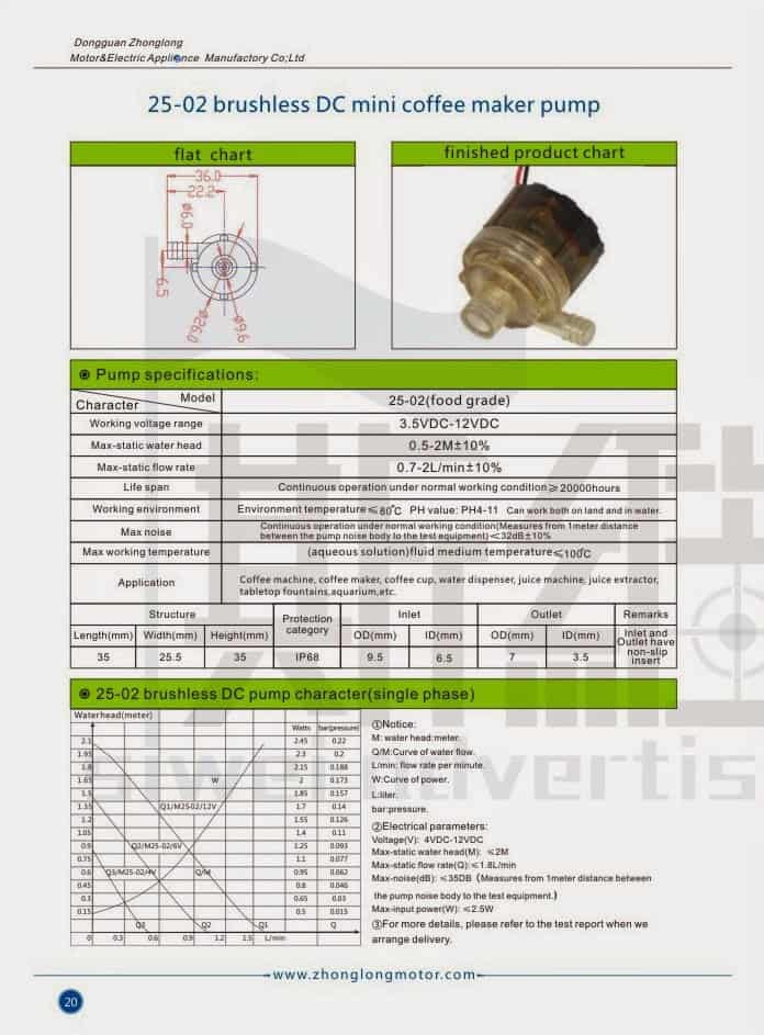
The pump typically runs at 0.15 to 0.25 amps and 4.5 to 6 volts. The data above provides the maximum operating conditions.

One end of the pump has a circuit board.

I've attached a very rough picture. Ultimately,

I'd like the manufacture to modify the circuit board to include the dry run protection. We need a very small circuit designed that would sense a change in current when the water level is below the pump.

Note that the pump is very small, and the circuit would need to be integrated into the existing board.

Would you be able to design a circuit for this application? If so, how much would you charge?

Cheers,

Ken Adler

President

Eagle Design

The Design

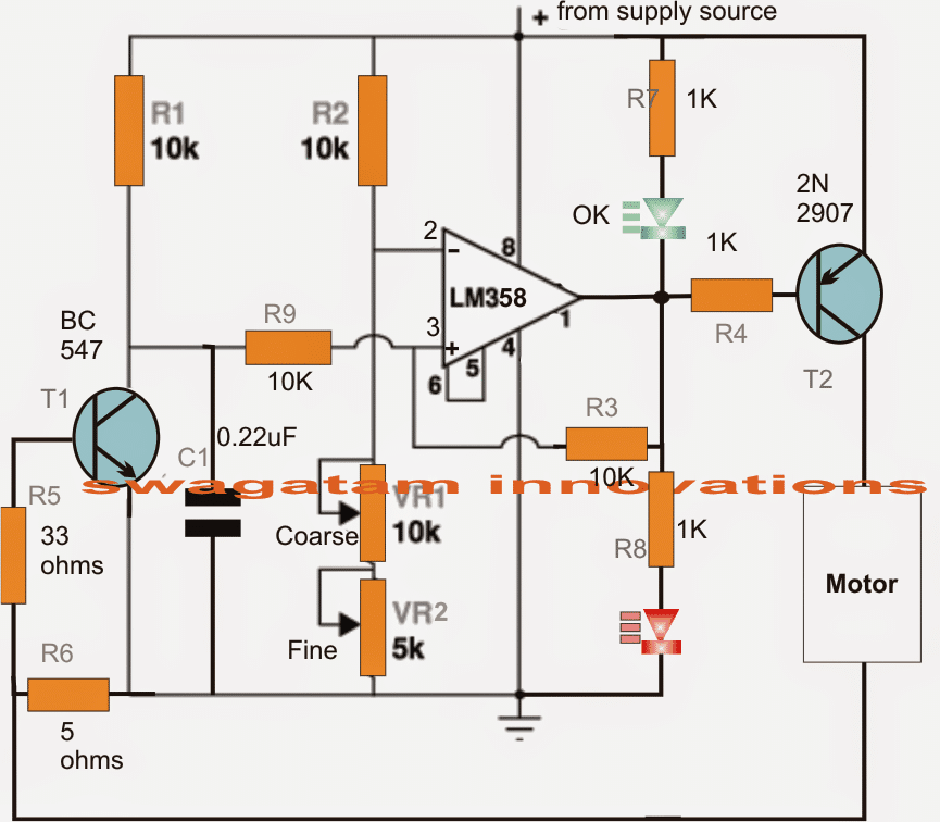
The requested mini coffee pump dry running protector circuit can be seen in the below given diagram, and may be understood with the help of the following points:

When power is switched ON, C1 pulls the non-inverting input pin3 of the opamp to ground so that an instantaneous low is developed at the output of the opamp.

This momentary low at the output triggers T2 which in turn initiates the connected coffee pump motor, which is assumed to be loaded here with the fluid content.

The motor switch ON causes the rated amount of current to flow through R6 which translates it into a proportionate amount of potential difference across itself and at the base of T1.

This prompts T1 to conduct and sustain pin3 of the opamp to ground so that T2 is able to hold the pump motor in the switched ON state.

Now suppose at some point of time the fluid level drops below the threshold forcing the motor to run dry, the motor current consumption also drops to a proportionate degree such that the potential across R6 becomes low enough to switch OFF T1.

As soon as T1 switches OFF, the potential at pin3 jumps above that of pin2 rendering a high at the output of the opamp which instantly switches off the motor preventing it from the "dry run" situation.

R3 makes sure that the situation gets latched ON and stays in that position until the tank gets filled and the circuit is reset by a complete switch OFF and switch ON.

Circuit Diagram

How to Set up the Circuit

  1. Initially keep R3 loop disconnected
  2. Also, disconnect the motor positive from the T2 and connect it directly with the positive of the supply so that while testing in switched ON condition the motor simulates a dry run situation (low current run)
  3. Now switch ON power, let the motor spin, and by little trial and error adjust VR1/VR2 until the red LED just comes ON, while the green LED shuts off.
  4. The pump dry run circuit is all set now, restore the R3 and the motor positive connections back to their original positions, test run the circuit under actual conditions with tank filled and empty for witnessing the intended protection features of the circuit.

You'll also like:

  • 1.  High Current Motor Control Circuit using Arduino
  • 2.  Adding a Soft Start to Water Pump Motors – Reducing Relay Burning Problems
  • 3.  Electric Wheelchair using BLDC Motor
  • 4.  Make this Electric Scooter/Rickshaw Circuit
  • 5.  Two Pipe Water Pump Valve Controller Circuit
  • 6.  PWM Motor Soft Start Circuit to Prevent High Consumption during Power Switch ON

About Swagatam

I am an electronic engineer (dipIETE ), hobbyist, inventor, schematic/PCB designer, manufacturer. I am also the founder of the website: https://www.homemade-circuits.com/, where I love sharing my innovative circuit ideas and tutorials.
If you have any circuit related query, you may interact through comments, I'll be most happy to help!

Have Questions? Please Comment below to Solve your Queries! Comments must be Related to the above Topic!!

Subscribe
Notify of
0 Comments
Inline Feedbacks
View all comments

Primary Sidebar

Calculators

  • 3-Phase Power (15)
  • 324 IC Circuits (19)
  • 4017 IC Circuits (52)
  • 4060 IC Circuits (25)
  • 555 IC Circuits (98)
  • 741 IC Circuits (19)
  • Arduino Engineering Projects (83)
  • Audio and Amplifier Projects (114)
  • Battery Chargers (82)
  • Car and Motorcycle (94)
  • Datasheets (46)
  • Decorative Lighting (Diwali, Christmas) (33)
  • Electronic Components (100)
  • Electronic Devices and Circuit Theory (36)
  • Electronics Tutorial (116)
  • Fish Aquarium (5)
  • Free Energy (34)
  • Fun Projects (13)
  • GSM Projects (9)
  • Health Related (20)
  • Heater Controllers (29)
  • Home Electrical Circuits (102)
  • How to Articles (20)
  • Incubator Related (6)
  • Industrial Electronics (28)
  • Infrared (IR) (40)
  • Inverter Circuits (98)
  • Laser Projects (12)
  • LED and Light Effect (93)
  • LM317/LM338 (21)
  • LM3915 IC (25)
  • Meters and Testers (65)
  • Mini Projects (148)
  • Motor Controller (67)
  • MPPT (7)
  • Oscillator Circuits (26)
  • PIR (Passive Infrared) (8)
  • Power Electronics (34)
  • Power Supply Circuits (77)
  • Radio Circuits (10)
  • Remote Control (48)
  • Security and Alarm (61)
  • Sensors and Detectors (120)
  • SG3525 IC (5)
  • Simple Circuits (75)
  • SMPS (29)
  • Solar Controllers (60)
  • Timer and Delay Relay (53)
  • TL494 IC (5)
  • Transformerless Power Supply (8)
  • Transmitter Circuits (40)
  • Ultrasonic Projects (16)
  • Water Level Controller (45)

Calculators

  • AWG to Millimeter Converter
  • Battery Back up Time Calculator
  • Capacitance Reactance Calculator
  • IC 555 Astable Calculator
  • IC 555 Monostable Calculator
  • Inductance Calculator
  • LC Resonance Calculator
  • LM317, LM338, LM396 Calculator
  • Ohm’s Law Calculator
  • Phase Angle Phase Shift Calculator
  • Power Factor (PF) Calculator
  • Reactance Calculator
  • Small Signal Transistor(BJT) and Diode Quick Datasheet
  • Transistor Astable Calculator
  • Transistor base Resistor Calculator
  • Voltage Divider Calculator
  • Wire Current Calculator
  • Zener Diode Calculator

© 2023 · Swagatam Innovations

wpDiscuz