In this post I have explained about L298N dual H-bridge DC motor driver module which can be used to drive brushed DC motors and stepper motors with microcontrollers and ICs.
Overview
Modular circuit boards are best time savior for electronics designers which also reduce the prototyping errors. This is mostly preferred by programmers who write code for microcontrollers spend their majority of the time by typing codes in front of the computer and have less time for solder the discrete electronic components.
That’s why we can find tons and tons of different modular circuits are made just for Arduino boards, it is easy to interface and have advantage of least hardware errors while designing our prototype.
Illustration of L298N module:
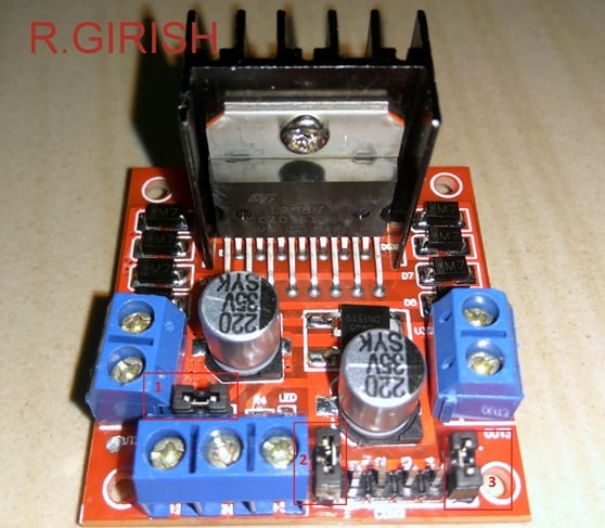
The module is built around IC L298N; it is commonly available at E-commerce websites.
We use DC motor drivers because the ICs and microcontrollers are not capable of delivering current not more than 100 milliamps in general. The microcontrollers are smart but not strong; this module will add some muscles to Arduino, ICs and other microcontrollers to drive high power DC motors.
It can control 2 DC motors simultaneously up to 2 amps each or one stepper motor. We can control the speed using PWM and also its rotational direction of the motors.
This module is ideal for building robots and land moving projects such as toy cars.
Let’s see the technical details of L298N module.
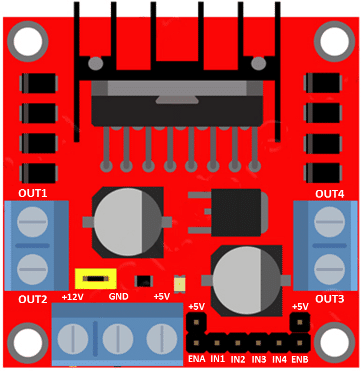
Pin description:
· On the left hand side there are OUT1 and OUT2 port, which is for connecting DC motor. Similarly, OUT3 and OUT4 for another DC motor.
· ENA and ENB are enable pins, by connecting ENA to high or +5V; it enables the port OUT1 and OUT2. If you connect the ENA pin to low or ground, it disables the OUT1 and OUT2. Similarly, for ENB and OUT3 and OUT4.
· IN1 to IN4 are the input pins which will be connected to Arduino. If you input IN1 +Ve and IN2 –Ve from microcontroller or manually, the OUT1 turns high and OUT2 turns low, thus we can drive motor.
· If you input IN3 high, OUT4 turns high and if you input IN4 low OUT3 turns low, now we can drive another motor.
· If you want to reverse the rotational direction of the motor just reverse IN1 and IN2 polarity, similarly for IN3 and IN4.
· By applying PWM signal to ENA and ENB you can control the speed of the motors on two different output ports.
· The board can accept from 7 to 12V nominally. You can input power at +12V terminal and ground to 0V.
· The +5V terminal is OUTPUT which can be used to power Arduino or any other module if needed.
Jumpers:
There are three jumper pins; you can scroll up see the illustrated image.
All the jumpers will be connected initially; remove or keep the jumper depending on your need.
Jumper 1 (see illustrated image):
· If you’re motor need more than 12V supply you have to disconnect the jumper 1 and apply desired voltage (maximum 35V) at 12v terminal. Bring another 5V supply and input at +5V terminal. Yes, you have to input 5V if you need to apply more than 12V (when jumper 1 is removed).
· The 5V input is for proper functioning of the IC, since removing the jumper will disable the in-built 5v regulator and protect from higher input voltage from 12v terminal.
· The +5V terminal acts as output if your supply is between 7 to 12V and acts as input if you apply more than 12V and jumper is removed.
· Most of the projects just need motor voltage below 12V so, keep the jumper as it is and use +5V terminal as output.
Jumper 2 and Jumper 3 (see illustrated image):
· If you remove these two jumpers you have to input the enable and disable signal from the microcontroller, most of the users prefer removing the two jumpers and applying the signal from microcontroller.
· If you keep the two jumpers the OUT1 to OUT4 will be always enabled. Remember ENA jumper for OUT1 and OUT2. ENB jumper for OUT3 and OUT4.
Now let’s see a practical circuit, how can we interface motors, Arduino and supply to the driver module.
Schematic:
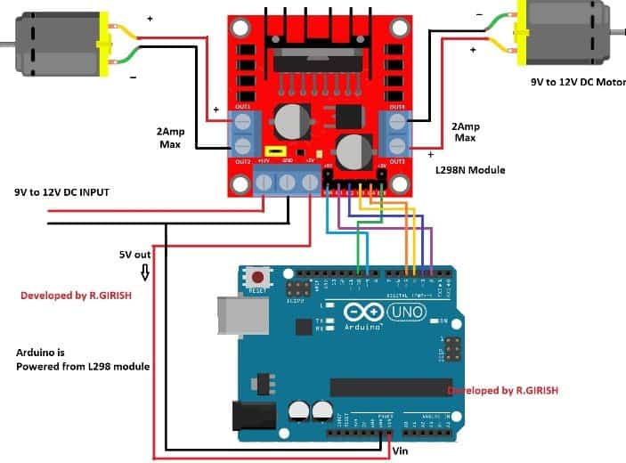
The above circuit can be used for toy cars, if you change the code appropriately and add a joystick.
You just need to power the L289N module and the module will power the Arduino via Vin terminal.
The above circuit will rotate the both motors clock-wise for 3 second and stop for 3 second. After that the motor will rotate anti-clockwise for 3 seconds and stop for 3 seconds. This demonstrates the H-bridge in action.
After that both the motor will start rotating slowly in anti-clockwise gaining speed gradually to maximum and gradually reduce the speed to zero. This demonstrates speed control of motors by PWM.
Program:
// Original Program was by R.GIRISH - This one is the new Improved version

const int Enable_A = 9;
const int Enable_B = 10;

const int inputA1 = 2;
const int inputA2 = 3;
const int inputB1 = 4;
const int inputB2 = 5;

const int RUN_TIME = 3000;
const int RAMP_DELAY = 40;

void motorA_forward(){ digitalWrite(inputA1, HIGH); digitalWrite(inputA2, LOW); }
void motorA_reverse(){ digitalWrite(inputA1, LOW); digitalWrite(inputA2, HIGH); }

void motorB_forward(){ digitalWrite(inputB1, HIGH); digitalWrite(inputB2, LOW); }
void motorB_reverse(){ digitalWrite(inputB1, LOW); digitalWrite(inputB2, HIGH); }

void motors_enable(){ digitalWrite(Enable_A, HIGH); digitalWrite(Enable_B, HIGH); }
void motors_disable(){ digitalWrite(Enable_A, LOW);  digitalWrite(Enable_B, LOW); }

void ramp_speed_up() {
  for(int i = 0; i <= 255; i++) {
    analogWrite(Enable_A, i);
    analogWrite(Enable_B, i);
    delay(RAMP_DELAY);
  }
}

void ramp_speed_down() {
  for(int i = 255; i >= 0; i--) {
    analogWrite(Enable_A, i);
    analogWrite(Enable_B, i);
    delay(RAMP_DELAY);
  }
}

void setup() {
  pinMode(Enable_A, OUTPUT);
  pinMode(Enable_B, OUTPUT);
  pinMode(inputA1, OUTPUT);
  pinMode(inputA2, OUTPUT);
  pinMode(inputB1, OUTPUT);
  pinMode(inputB2, OUTPUT);
}

void loop() {

  motors_enable();
  motorA_forward();
  motorB_forward();
  delay(RUN_TIME);

  motors_disable();
  delay(50);

  motors_enable();
  motorA_reverse();
  motorB_reverse();
  delay(RUN_TIME);

  motors_disable();
  delay(50);

  ramp_speed_up();
  ramp_speed_down();

  motors_disable();
  delay(RUN_TIME);
}
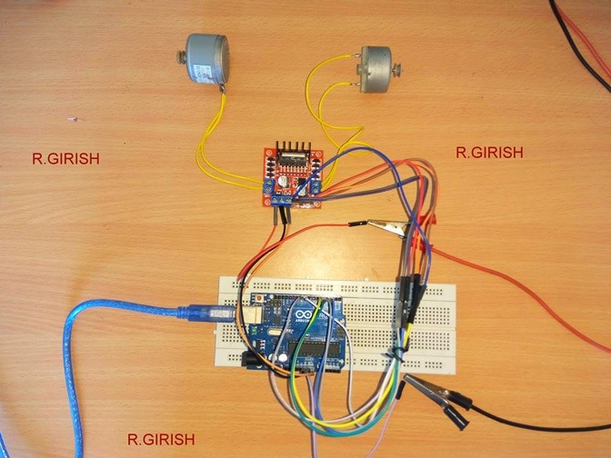
Author’s prototype:
If you have any questions regarding this L298N DC motor driver project, feel free to express in the comment section, you may receive a quick reply.


Questions & Answers
i have 12v, 17 amp battery but when i use mosfet to drive the moter the voltage drops at 3 to 4v on load .i simply connected the irf450 mosfet.in darlinton configration .my moter is about 5 amp nd 12v . i want my moter to run on full speed . its speeds good when without mosfet .but power down when mosfet connect and run throug aurdiuno pwm with 255 max speed.
Where exactly the voltage is dropping, is it across the motor or across the battery? I assume it’s across the motor, in that case your Arduino may be wrongly coded or the mosfet the faulty.
sir , i have made a CIRCUIT LINK below .a moter driver circuit . its working fine when no load on moter but when i loaded moter with load its sound beep . and motor stopped. i have use power mosfets whos rating are 42 amps and voltage rating is also upto 24.
Muhammad, please show me the exact circuit schematic so that I can understand better, or you can refer to the following links and make one one of these, all are perfectly tested:
https://www.homemade-circuits.com/dc-motor-speed-controller-circuits/
sir, i m looking for a circuit electronic fule injection ..to make my final year project if u have any infomation so kindly ,share it to me how to statrt up
Muhammad, sorry I do not have any circuit related to the electronic injection fuel at the moment
I am using 12v external power supply… And I had removed the jumper.. But still it gives 6v on out A.. What I have to do…?? Please reply quickly
Hi Laavanya,
Which jumper you are referring to, there are 3 of them and which output you are referring to OUT1 to OUT 4?
Regards
I’ll forward this question to Mr. GR, he will reply you soon!