In this post I have explained a simple remote controlled solar lamp intensity controller circuit which can be used for controlling the street lamp LED intensity without practically reaching for the LED box. The idea was requested by one of the dedicated members of this website
Circuit Objectives and Requirements
- I have successful build this current controlled driver circuit with a 50 watt LED (5 x 10 watt) for a garden light.
- So far i don't want to use it the whole night and because of its elevated position (it will be about 4-5 meter above the
earth),manual Switching is not preferable. - Therefore would you mind suggesting me any remote control circuit for Controlling LED Intensity? counting on your usual co-operation!
The proposed circuit can be built using the below shown circuit design.
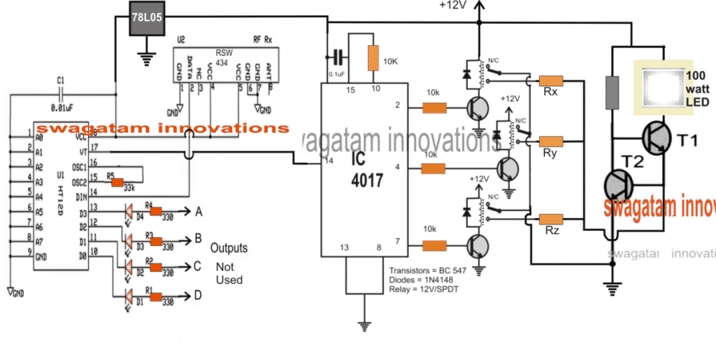
The Design
The design employs 3-step intensity control for the connected LED lamp which could be easily converted to a 10-step intensity controller by simply repeating the indicated relay driver stages across all the 10 pinouts of the IC 4017.
The circuit basically is made up of 3 distinct stages, which can be understood from the following explanation:
The first stage from right is a transistor based LED current controller circuit which has been already built by the user as the solar lamp, who requested this article.
The central IC 4017 stage is a 3 step relay selector switch circuit which toggles sequentially across the relay stages switching the relays ON/OFF one at a time in response to every single pulse at its pin#14.
The 3rd stage at the left side is an RF remote control receiver module, whose VT pinout is configured with the pin#14 of the IC 4017.
The pin VT of the remote module IC HT12D blinks once, each time the remote transmitter handset button is pressed (any button out of the 4 buttons).
This blinking of the VT pin is used as the toggling pulse for the IC 4017 which responds instantly causing the subsequent relay to latch, and releasing the previous relay in the sequence.
The relay contacts can be seen configured with current determining resistor Rx, Ry, Rz, which are correspondingly selected from a higher value to a lower value and vice versa by the relay contacts.
These resistors get linked with the current controlled LED driver stage altering the current restriction levels of the LED driver stage.
This action in turn renders the LED with a corresponding amount of current limit producing an equivalent level of illumination on the LED, lower current causes the illumination to decrease and thesubsequent higher current selection allows the LED intensity to grow brighter depending on which resistor is toggled ON by relays.
The resistors Rx, Ry, Rz can be calculated by the formula provided in this 100 watt LED driver circuit article
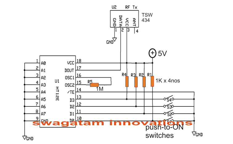
The transmitter circuit for the above explained remote controlled solar lamp intensity controller circuit can be witnessed in the following diagram and built accordingly for the lamp intensity control.

Questions & Answers
Must pin 15 and pin 10 be connected together or i can connect pin 15 to any of the remaining unused output pins of 4017 ic
pin10 is just after pin7 so it resets immediately after pin7, any other pin will cause the reset to be delayed depending on the order of the pin number
Hi Swag
I understood your explanation above. But I’m a little bit confuse. Only three output pins were used. Since its a sequencial ic will the remaining output unused pins create an extra delay before we returned back to the above three used pins? I really hope my question will be understood. Thanks alot for the great work.
Hi Abba, the pin 10 is connected to the reset pin of the IC, so after pin7 the sequence will quickly return to pin3 and repeat the procedure.
Thanks alot for your timely reply. I appreciate it.
Dear Sir, I note that you make a non conventionnal and original use of the 4017 in lots of your creations. The 4017 is a very common chip, easy to find and not expensive at all. I can only congratulate you for your work. Thanks.
Thanks Rafu, I appreciate your observation and interest…keep up the good work.