In this post I have explained how to use Bluetooth technology for transmitting PWM wirelessly, the circuit application could be used for controlling various appliances such as motors, lights, RC gadgets etc using your Android phone.
The Bluetooth PWM Transmitter
In one of my earlier posts I explained how to hack and modify a Bluetooth headset for making a Bluetooth Home-theater system, the same concept can be employed here for controlling a preferred appliance such as a motor using Bluetooth PWM.
There are actually two options to transmit Bluetooth PWM, one is by using a specialized Bluetooth transmitter module and a function generator circuit, or a much simpler modified Bluetooth headset gadget.
In this article I have explained how the second option could be used for implementing the proposed Bluetooth PWM motor controller circuit.
The idea is actually as simple as integrating the Bluetooth headset speaker wires with a mosfet or BJT motor driver stage, that's all.
The details can be seen in the following figure.
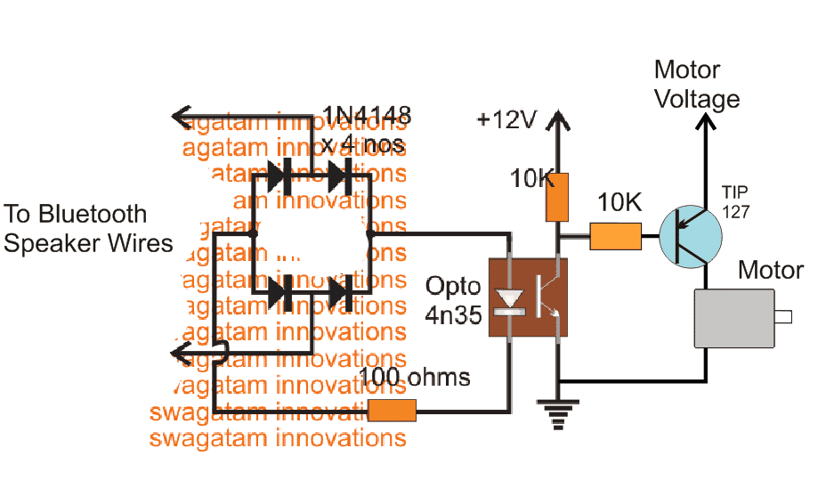
The above set up shows an external PWM motor driver simply configured using some diodes, an opto-coupler and a BJT stage.
The PWM from the Bluetooth Headset is passed through a bridge diode network and then applied at the input of an opto coupler.
The output from the opto coupler is finally fed to a motor driver stage.
Now as the PWM from Bluetooth headset is changed, the motor responds to the PWM and correspondingly changes its speed.
How to Obtain the PWM Transmission for the Bluetooth Headset
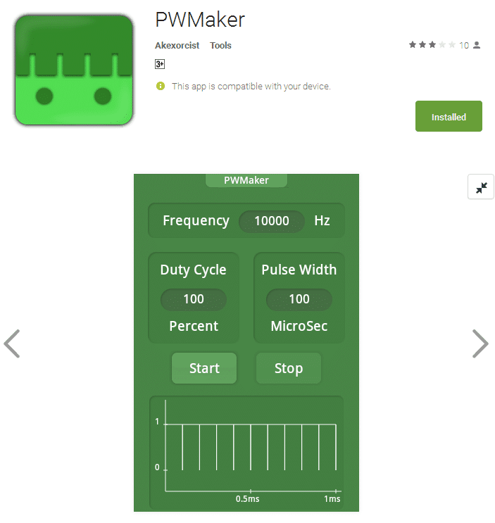
The PWM transmission for the Bluetooth headset can be obtained from your Android phone.
For this you may have to install any standard PWM generator application and then "pair" it up with your Bluetooth headset.
Next, you would be prompted to adjust the duty cycle, PWM, frequency etc within the application, which you can fix as per your preferences.
Once all these initial set ups are completed, the PWM transmission for the Buetooth headset could be initiated for executing the motor control operations.
The PWM or the frequency could be changed as per your wish and will, from your android phone application whenever the speed of the motor is required to be altered.
This concludes our tutorial on Bluetooth PWM motor controller circuit, which looks extremely simple and useful, thanks to the all latest technology like android applications and Bluetooth features.


Questions & Answers
I hope this forum could help me with a little drone project… I have a PWM signal that I need to transfer to a device attached to a moving gimbal. This makes the use of wires impossible.
Would it be possible to send this PWM signal wirelessly, then back to PWM?
Alternatively, my gimbal has S. BUS and CAN-BUS, so I am wondering if I can convert PWM to BUS and back again.
Thanks in advance for *any* input
Cheers
Hi, I am not sure how S.BUS or CAN-BUS can be used for the pwm communication, however PWM can be sent wirelessly through 433MHz RF modules, if integrating these modules is possible, then I can perhaps help…
Ok I got it,I will try and inform you.
Thanks.
Many thanks for quick reply.Your advise
Very helpfull to me but I have tried to search on google your suggested link " fly-back regulator" but failed.
hi SWAGATAM thanks for all your work and this massive technology , now what if i want to add more motors like three of them how can i modify this
Thanks Davis, you can add all the 3 motors in parallel….
Sir if kindly answer my question I will be thankfull to you. I have a battery charger build with Ic 3843
8 pin ossilator. How to increase amp and voltage with simple change of Ic biasing.
Manas, please refer to the datasheet of the IC, and check out the diagram titled "27 Watt Off−Line Flyback Regulator", you will e able to see a 0.5 ohm resistor connected with the source of the mosfet…this resistor determines the current limit of the circuit, so you can change this resistor for the current adj….and the voltage will need a feedback loop using an opto coupler connected with a the Ct pin of the IC…that will be a little complex…
http://www.onsemi.com/pub_link/Collateral/UC3842A-D.PDF