In this post I have explained s few simple DC to DC buck-boost converter circuits which can be used for either stepping up the input DC voltage or stepping down the input DC voltage to specific output DC voltage levels.
Since a buck-boost converter allows the input voltage to be either stepped up or stepped down, hence it is named as buck and boost converter or buck-boost converter.
Basic Working principle
The basic working principle of a buck-boost converter can be understood with the help of the following explanation.
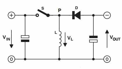
Referring to the basic buck-boost topology diagram above, when the switch S is closed, the input voltage VIN is blocked by the diode D, since D is reverse biased. Therefore the voltage has no other option but to flow through the inductor L.
The inductor L due to its inherent reluctance property initially tries to block the current. Due to this, initially the voltage drop across L is high. However, slowly as the reluctance of the coil decreases and the current through the inductor increases.
During this phase the inductor L stores the energy (voltage and current) inside its winding.
Ideally this the point when the switch S needs to be opened.
When switch S is now opened, the voltage VL stored inside the inductor reverses direction, and it passes through the diode D which is now forward biased. In the process VL also passes through the output capacitor and charges it fully.
During this phase the output capacitor stores energy inside it and gets fully charged, simultaneously the load across VOUT also gets the energy from the inductor for ts operation.
Next, at this point if the switch is closed again, the process repeats as explained above, however now the capacitor provides its stored energy to the load.
Depending how how fast or how slow the switch S is closed and opened, the output DC can be a stepped up or boosted output, or it can be a stepped down or buck output.
In a real life electronic buck-boost circuit, the switch S is replaced with a BJT or a MOSFET and this device is switched ON/OFF through an external PWM for generating a buck or a boost output.
Simple Two Transistor Buck-Boost Converter Circuit
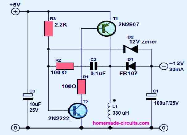
The following figure shows how a very simple buck-boost converter could be built using just a couple of transistors and a few other passive parts.
The working of the circuit can be understood from the following points:
Here the circuit is configured to provide a negative boosted output from a 5V input to a -12V output.
As soon as the circuit is powered, the T2 switches ON via R3. This allows T1 to also switch ON through the negative base bias received via R1 and T2.
This causes the full +5V to be applied across the inductor L1 via the collector of T1.
The inductor, due to it reluctance opposes the instant rise in current across it and in the process begins storing energy inside its winding.
Now, slowly the inductor reluctance drops and it starts passing more and more current through. Due to this the base current of T2 is pulled to ground through the inductor and via R2 and C2.
This causes T2 to shut off momentarily.
Now, the stored energy inside the inductor is released back to the output across C1.
C1 now charges fully and simultaneously the output is also supplied with a negatively boosted voltage.
The 12 V diode makes sure that the inverted output boosted voltage does not rise above -12V.
Subsequently C2 begins charging until it is fully charged, which allows T2 to switch ON again, and the process repeats. This repetition process continues at a high frequency.
The frequency of the converter is determined basically by the values of R2 and C2.
By appropriately tweaking the values of R2 and C2, this two transistor circuit could be optimized either to work like a buck converter or a boost converter.
Using IC 555 for the Buck-Boost
This highly efficient and effective buck-boost circuit using the work horse IC 555 would allow you to convert an input source voltage to any required degree, either bucked or boosted, as desired.
We have already learned the concept comprehensively through one of my previous articles where I have explained the versatility of this buck-boost type of topology.
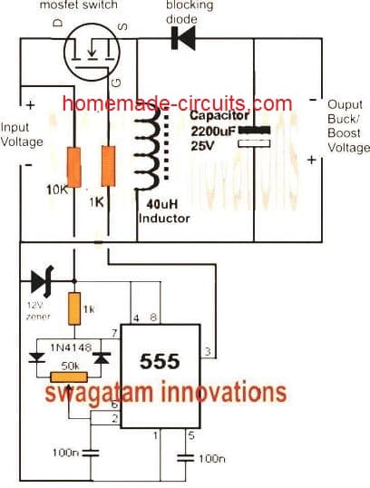
As shown in the circuit diagram below (click to enlarge) the configuration is basically a combination of two distinct stages, viz the upper buck-boost converter stage and the lower IC 555 PWM controller stage.
The buck-boost stage consists of a mosfet which acts like a switch, the inductor which is the main power converting component, the diode which just like the mosfet forms a complementary switch, and the capacitor quite like the inductor forms a complementary power converter device.
The mosfet needs to operate through pulsed triggering so that it alternately switches the input voltage ON and OFF across the inductor in response to its gate voltage.
Therefore the gate voltage should also be in a pulsed form which is accomplished through a IC555 PWM generator stage.
Circuit Operation
The associated IC555 PWM generator is integrated to the mosfet for accomplishing the above discussed operation.
During the ON time of the mosfet, the input voltage is allowed to pass through the mosfet and is applied right across the inductor.
The inductor owing to its inherent property tries to counter this sudden infliction of current by absorbing and storing the power in it.
During the subsequent OFF period of the mosfet, the input voltage is shut off by the mosfet, the inductor now experiences a sudden change in current from peak to zero. In response, the inductor counters this by reversing its stored power across the output terminals via the diode which now acts in the forward biased condition.
The above power from the inductor appears with opposite polarity across the output where the intended load is connected.
The capacitor is positioned to store a portion of the power in it, so that it can be used by the load during the ON time of the mosfet when the diode is reverse biased and power cut off across the load.
This heps to maintain a steady and stable voltage across the load during both ON and OFF cycles of the mosfet.
Using PWM as the Controller
The level of voltage, whether it's a boosted voltage or bucked voltage depends upon how the mosfet is controlled by the PWM generator.
If the mosfet is optimized with higher ON time than the OFF time then the output would generate boosted voltage and vice versa.
However there may be a limit to this, care must be taken not to exceed the ON time beyond the full saturation time of the inductor, and the OFF time must not be below the minimum saturation time of the inductor.
For instance suppose it takes 3ms for the inductor to become fully saturated, the ON time in this case can be set within 0 - 3ms, and not beyond that, This will result in a boost from minimum to maximum depending upon the value of the chosen inductor.
The associated pot wit the IC555 PWM generator can be effectively tweaked for acquiring any desired buck-boost voltage at the output.
The inductor value is a matter of trial and error, try to incorporate as many winding as possible for acquiring better and efficient results and diverse range.
Circuit Diagram
The above design can be suitably upgraded for implementing an automatic output voltage correction with the help of the following modifications:
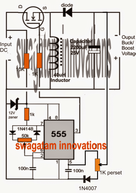
The 1K preset may be appropriately set initially for determining the desired control point.
IC 555 Pinouts
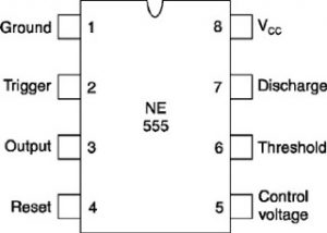


Questions & Answers
sir may i know the design considerations of this circuit sir?
Hi Raja,
No critical things are involved, just has to be built as per the given schematic.
Dear Swagatam,
whats the minimum value of input voltage, how much power does the circuit itself consumes and whats the max ampere capacity of the circuit
Dear kkaranjia,
minimum voltage is 5V
the IC will consume 5mA, not sure about the other components, will depend on how the coil and capacitors are optimized.
Max current will depend on the mosfet and inductor ratings, there's no restriction to it.
cant it be modified to run on li-ion battery and give op of 5volt
you will have replace the 555 oscillator with a transistor type oscillator, then it would be possible.
can you help me design that transistor type oscillator
I think you should try the following circuit, it looks more suitable for your application:
https://www.homemade-circuits.com/2012/10/1-watt-led-driver-using-joule-thief.html
dear swagatam i want constant 5v o/p to charge the mobile battery so is this concept usable there ?/
You can use a 7805 at the output with a 1n4007 in series, that will hopefully do the job.
wont the o/p be fluctuating and wont it harm the mobile…?
what is the input voltage?
will be using 3.7 volt Li-ion battery so the input will vary from 4.2v to 3.6v
i did not quite understand, you want to use a 3.6V Li-ion battery at the input for charging another 3.6V Li-ion battery at the output???
yes you are right i want to do that but some mobile phones like micromax wont get charged if it is supplied below 5volts.
OK, understood.
The linked circuit which you provided is fine, you can make it.
Hi Bro, I'm newbie electronic hobbies, and become addictive due to the articles at your site. Kudos for you.
Right now I'm trying to built the above circuit, but do not have the right inductor in hand.
Could you guide me for diy to make an alternate inductor using ferrite rod dia. 10 mm x 80 mm long with isolated single core wire from regular power cord?
Btw, refer to your above design, are the 2 diodes arrangement across the 50K Pot correct?
Thank you for your help and regards.
Ferry
Thanks Bro,
you can proceed with the listed inductor materials, however it will need to be done through trial and error, by altering the number of turns and by checking the output voltage correspondingly.
Yes the two diodes are connected across the two ends of the pot, you can click the diagram to enlarge.
Thanks for your reply Bro,
Just fyi, I have tried with 682 inductor (that off-course far away from your suggested value), bypassing the Zener diode and the 10K resistor across it, and feed the circuit with 12 V lipo battery, max output was only about 3.6V, mosfet and inductor became hot. I will try it again later with suitable variable inductor if I get it in hand.
Thanks again and have nice week end days.
Ferry
The above circuit can act both as a buck converter or a boost converter, will depend on how the 555 pwm output is adjusted, also the inductor will need to be dimensioned as per the load current (amps) for optimal functioning.
Hi want convert 24 to 12 dc to dc is possibe with ne 555 buck convertor
yes it's possible.
please give rating of all the compnents used
mosfet is IRF540, rest everything is given in the diagram, please click it to enlarge.
blocking diode is BA159
i love the design im kinda curious what the amp rating would be in the current configuration that way i can try to boost it or build 3 of these units in parrellel for a solar project to handle 100 Amps from solar
amp rating can be of any value as required by the user, for acquiring 100amp you could just use 3nos of IRF540 in parallel in the same circuit
try a 1K 2 watt resistor.
the maximum wattage of your panel is 14 x 3 = 42 watts, so you cannot get by any method an output more than 40 watts from your solar panel….so 100 watt is entirely beyond range.
Hi Swagatam, if I want to change my 555 timer to a duty cycle of 70% what values do I change on the circuit above
Hi Vongani,
you can do it by adjusting the given pot and simultaneously checking the pin3 DC voltage with a meter, when the meter reads 70% of the supply then you can be sure of the required level being achieved, for example if the supply 10V then the meter should indicate 7V at pin3 of the IC 555
Sir Swagatam how do I change the duty cycle
Dear Mr Swagatam,
what components should be added to make the dutycycle automatically adjust itself according to the varying load? This means that the output voltage stays stable at a predetermined voltage regardless any changes in load. I'm thinking about IC LM2575 here as a comparison, which has an add-on voltage reference (voltage divider) on the output. Thank you.
Dear Imanul,
I'll update the diagram with the required feature and post it…soon.
Sir, Have you made the circuit ?
Sir, what is the maximum voltage input?
it can be anything, you just have to upgrade the fet, the capacitor and the 555 IC input resistor watt accordingly.
which resistor is the 555 input resistor?
which input? do you mean the supply input?
Yes, the supply input
And to be more exact what is the maximum supply input for the design above (with no changes)
Also, what the wattage of the resistors in the path for the 555.
How can I calculate the required resistors (in the supply path for the 555) values for higher or lower voltages?
if I wanted to use higher voltages (60+ Volt DC unregulated) should the L (in Henry) and C in Farad values stay the same or should I recalculate it based on of your other articles (https://www.homemade-circuits.com/2013/06/exploring-buck-boost-circuit-concept-in.html)
Thank you in advance
the 10k resistor connected with the pin4/8 of the IC 555 is the supply input resistors for the IC.
using a 1 watt for this resistor will be enough for upto 60V
rest all can be 1/4 watt
L will need to changed for different volt inputs…. by rule of thumb it could be 1 v per turn, that is 60 turns for 60V
the supply resistor can be calculated by using the following formula:
R = V/0.01
answer will be in ohms
Thank you very much for your detailed answers,
May I ask more questions?
in case of yes,
What is the operating frequency of 555 o/p ?(i think frequency here is independent of duty cycle percentage right?)
How can I change the operating frequncy? (which components decide it?
I assume the 100nF connected to the 50k pot is responsible for the frequency with the 50K am I right?
what if I changed the 100nF (because I do not have it for example ) to 220nF, what else I should change?
and how to tweak or tune the switching frequency?
Thank you in advance
the frequency should be above 50kHz for optimum response from the ferrite inductor.
frequency can be changed by changing the piin6/2 capacitor, 50k is for changing the duty cycle, not the frequency
the duty needs to be tweaked for adjusting the current of the output with respect to the load, frequency can remains constant.
Hi Swagatam,
I am a newbie to electronics and an avid reader of your blogs.
I need a voltage booster (12 volt input – (variable) max 22 volts out) circuit to be connected in series with the load. i.e. the circuit will be connected between the battery (12 volts) and the load hence I need only 2 wires on the circuit (series connection).
Can this circuit be modified for series application? If possible could you please suggest how I should modify it?
Also the power draw would be 15Amps DC max. Could you please suggest the ferrite core inductor size and winding wire details to make it capable of 15 Amps max?
Appreciate your help.
Thanks!
Hi Swagatam!
I am a newbie to electronics and an avid reader of your blogs.
I need to connect a pwm based variable voltage booster circuit in series between the battery and the load.
Input voltage : 12 Vdc
Output voltage : Variable up to 24 Vdc Max
Max amps : 10 – 15 A max
For this circuit, I need only 2 wires (one input and one output) to be able to connect in series with the load.
Is it possible to modify the 555 based buck boost circuit for this application?
Also could you please suggest the inductor type and the wire winding details for this circuit?
Appreciate your help.
Thanks!
Hi VM, yes you can try the first circuit from above for getting the required output.
the circuit has two wires only, there's no third wire here.
the inductor number of turns should be twice that of the supply voltage input wound over a ferrite rod or any suitable ferrite core, wire gauge can be 22SWG
Hi Swagatam,
Thanks for your quick response.
I have made a drawing for your reference to exactly show how I intend to connect this boost circuit.
https://drive.google.com/file/d/0B7h83BRbOTR0QlJTc3EtQnNoa0U/view?usp=sharing
After checking the drawing, could you please update which points I should connect exactly?
Also for the ferrite rod or torroid core, is there a specific minimum diameter I should use for maximum efficiency?
Thanks for your help once again.
Hi VM, after you make the above circuit connect the 12V source to the left side "input voltage" points and the load across the right hand side "buck/boost" points.
The formulas for calculating the parameters are extremely complex…you can try it by trial and error….you can start with a ferrite rod which were used in AM radios long ago.
Number of turns can be around 30 to 40 using any magnet wire between 22 to 27 swg
Sir.I like your blog so much most of the circuit u posted in this blogs works well.now I need a circuit to charge my 6v.1.3ah battery from 6v.300ma current rating solar panel.can I use this circuit to increase a voltage in range of 7v
Thanks Vijay, the above shown designs can be a little complex for your need, instead you can try the following circuit and optimize the coil to suit your application need
https://www.homemade-circuits.com/2015/02/6v-to-220v-boost-ups-circuit-for.html
Thank you very much sir for your reply.I need one clarification sir whether this circuit automatically change from buck mode to boost mode and boost mode to buck mode based upon the need????
as far as I have understood yes this circuit can be used for achieving both buck and boost outputs depending on the setting of the PWM pot.
Thanks again for your reply sir. Please help me to solve this doubt sir. I am using 18v solar panel to charge my 12 v battery. I build your lead acid battery charging circuit successfully thanks for posting useful circuits. I noticed one think that by using lm317 i made a constant voltage to charge my battery at this case we are losing some amount of energy in the form of heat to avoid this I planned to use a buck boost circuit for following reason
1) If the solar panel output is to high for ex. If I get 18v from the output of solar panel to charge 12v battery I planned use this remaining 6v to increase the value of current to increase the efficiency of charging by using buck circuit
2)In the case if the solar panel output voltage decrease at evening period, at this time I need to step up the voltage for few period of time by using boost circuit
Shall I use this circuit to do both process automatically?? Whether this circuit works or not.please reply me sir
Vijay, a 12V battery will require minimum 14V to get optimally charged so there would be hardly 4V extra for you to use during peak sunshine.
Yes you can try out the above design, and try adjusting the PWM control to achieve the results, however you may have to adjust the pot every after 3 hours to regulate the output, I am not very sure abut the proceedings since I haven't yet tried the concept practically.
OK sir. If there is any circuit with window comparator and rtd to make the pwm automatically without adjusting the pot manually. Similar to solar tracking system circuit u posted
Vijay, you can try the first circuit from this article:
https://www.homemade-circuits.com/2014/11/self-optimizing-solar-pwm-charger.html
Sir can u please tell me how this 555ic produces pwm.I am 3rd year eee student in my books they used reference and carrier signal to generate pwm. I didnt see any reference and carrier signal on this circuit.please reply sir
Vijay, the reference is fixed at pin#5 of the IC internally…while the pot value determines (adjusts) the peak volatge of the triangle waves at pin7 ….which is compared with the potential at pin5 for dimensioning the PWMs.
dear mr. Swagatam,
I want to boost a dc input that can vary from 1.2v to 4.3v to an output voltage between 5v-20v (that i adjust) and it should be regulated. can i use your circuit? if not, what do you recommend me to do ?
The above circuit won't work because the minimum voltage spec is 4.5V, I think you should go for a joule thief kind of circuit, you could probably try out the following:
https://www.homemade-circuits.com/2012/10/1-watt-led-driver-using-joule-thief.html
Hello Swagatam, i love the work you do. I have been following your Simple Solar Mppt Part 2 and than I look at this unit over and over again thinking Wouldn't a buck boost type system be simpler using pwm. Is there something I am missing as to why this with a battery charger setup added wouldn't be better as a charge Controller?
Hello Mark,
thanks very much for liking my site.
managing and optimizing two features together could pose some complication that's the reason I included only the buck converter in my MPPT design, and if a boost converter is required in the design one can apply it separately through a different set of calculation.
Hello sir, please what is the different between this design and this https://www.homemade-circuits.com/2014/11/self-optimizing-solar-pwm-charger.html and which one is more effective and optimise? Thanks for the good work you are doing here.
Hello emmantrop, both are effective depending on the panel specs…if panel is low current high voltage type then the linked article idea is good, if the panel is low voltage high current type then the buck/boost concept can be better.
Hello Sir. First time on the website. Glad to see intellectuals like you.. I am designing a buck boost circuit. For now my circuit differs in two ways.
1 I am giving the the PWM through a function generator.
2. I am using IRF840. The problem is it switches at 20 volts.Which is quite strange. what am i doing wrong? Should a resistor be attached before the pulses go to the gate?
3. What type of Load are you using ? Is it dynamic or static? to what limitations should i consider while using a load of DC motor of 24V and 2amperes?
Your help will be highly appreciated 🙂
Hello Owais,
the PWM can be fed from any source that's not critical.
the fet should start working from 9V onwards, so 20V is abnormal, may be the fet is faulty or duplicate…I would recommended a BJT first to check the response and then you can replace it with an FET later on.
The load power requirement should not exceed the FET or BJT power specs…that's the only thing we have to take care of, rest of the optimization will depend on the input power specs, the PWM duty cycle and the output capacitor.
sir i am working on pedal power generation project i am using a car alternator whose rating is 12v 49amps when i am driving the alternator i am getting a constant output of 15v . i want to boost the voltage till 26v so i can charger 2 12 volts battery in series
and buck it to 6v and 14v so can i use this circuit if not what changes must be done
how can i vary the voltage which one acts as a potentiometer
salmanblast98@gmail.com
Salman, you can use the available 15V itself and charge the batts directly, in parallel instead of putting them in series.
for buck conversion you can try the following design:
https://www.homemade-circuits.com/2015/05/5v-pwm-solar-battery-charger-circuit.html
Hello sir, What can be the Max input and output?
It can be configured at any desired level
Sir, I will like to get 5v 2A as an output to power 4 devices of the same rating. Input will be 20v 7A. Please how do I do that?
Ello, your application is of a buck converter, so you can try the last circuit from this article
https://www.homemade-circuits.com/2015/10/calculating-inductor-value-in-smps.html
the details are provided in the article itself
sir, how did you calculate the values of the inductor and capacitor??
I went through your article on "how buck boost converters work" and texas instrument page on buck boost design,but did not find any formulas for inductor and capacitor calculations.
I want to design a circuit with 12V input and 24V output,could you please give me the inductor and capacitor values and the formulas you used.
Ajay, I have tried to explain a simpler approach for the new hobbyists through this article
https://www.homemade-circuits.com/2015/10/calculating-inductor-value-in-smps.html
for a more technical approach you can read the following article
https://www.homemade-circuits.com/2015/10/calculate-current-voltage-buck-inductor.html
for the calculating capacitor, you can probably apply the theory explained in this article
https://www.homemade-circuits.com/2015/11/calculating-filter-capacitor-for.html
hello sir need some help regarding the circuit i made it but output is giving me what i want thats 24v. input is 12.9v pin #3 of ic is 5.6v and output is giving me 5.5v.yet i have changed inductors from 40uH to 150uH thanks your help is apreciated
Olupot, do one thing, try the concept which is presented in the following article, it is the traditional concept and easier to adjust
https://www.homemade-circuits.com/2014/11/12v-car-laptop-charger-circuit-using.html
ignore T2 stage initially
Hi Engineer Swagatam, Please can I use any diode for the blocking diode thanks.
Hi Mamman, any diode will not do, you will have to use a fast recovery type of diode…you can try a BA159
Hello Engineer Swagatam, Thanks for you nice work. Please can I use any rectifier diode for the blocking diode?
Dear sir,
How much current I draw from this circuit? I know it’s depend on mosfet and inductor but i want to know max. amount of current if I want.
Thanks
Max current will depend on the max capacity range of the mosfet, coil and the diode rating
I think so.
Thank for your reply.
From the above circuit does it mean that the input GND voltage become the output POSITIVE voltage?
yes that’s right, as per the concept it becomes positive for the load only during mosfet switch OFF periods
hello, i am making a booster circuit with 5v output using your circuit but the voltage output isnt 5v. is it okay to use any mosfet? i used stk0825 but the output is below 1v. my input voltage is 3.7v li-ion battery, and the coil i used is toroid coil with 30 turns. i also used a 16v 1000uf. also, the preset i usedwas 103.please give me some advice
I have not yet tested the circuits explained in the above article, Please try one of these designs instead:
https://www.homemade-circuits.com/how-to-make-simple-boost-converter-circuits/
Hello Sir, recently i came across this website, and truly I am in love with this. A big salute to you work. My doubt is that, can Buck-Boost Converter generate a fixed output voltage with and unregulated/ variable input voltage.
Actually i wanted to use Solar Panel as my Power Supply Source which does not provide a fixed voltage source. So can we use Buck-Boost Converter for the above situation?
Thank you Ashish, Glad you liked my site! Buck/Boost converter will not produce a fixed output if its input changes. However if you have a PWM feedback system then you can get a relatively constant output
Thank you so much for your reply sir. It means a lot sir. Other than PWM feedback system, can we use a SMPS because according to my research, A SMPS generates a regulated voltage(fixed voltage) from an unregulated voltage.
Do you have any suggestions regarding SMPS circuits, because as discussed above, my aim is to get a fixed voltage (which can be varied) from solar panel (whose output voltage is not fixed) to charge a battery through a smart charger.
Please do hep sir.
And lastly, thank you so much sir for taking out time and giving a reply to my doubts. Seriously, means a lot.
Thank you Ashish, The buck boost itself is a switching or SMPS circuit. Do you mean a circuit having a fixed PWM? But in any case a feedback will be required for regulating the output. I have a couple of designs which are discussed in the following articles, but I do not have a buck-boost type circuit.
https://www.homemade-circuits.com/5v-pwm-solar-battery-charger-circuit/
https://www.homemade-circuits.com/generating-electricity-from-road-speed/
I hope this helps!
Thank you again sir for replying. Actually i want a circuit that can provide a fixed output voltage (which can be varied according to our need) from an variable input voltage (solar panel is my input power source).
As you said earlier, a PWM feedback system would do my work. So can you help me with any circuit available in this site regarding PWM feedback system or any other circuit that can do what i want.
And could you please tell me in short the function of 5v pwm solar battery charger circuit (the circuit which you recommended me in your earlier post) if you don’t mind.
Hi Ashish,
The 5V pwm converter will give you a fixed output which can be adjusted by changing the R8/R9 values. But since it is a buck converter its output will be always lower than the input, it cannot be higher than the input.
DEar Sir,
Why and how the o/p freq. changes due to loading effect of a 555 AMV? If possible please help me to find out for proper design.
Thanks. Regards,
Soubhik
Dear Soubhik, did you try this practically? If yes please explain a little regarding its output and input responses, I’ll try to figure it out?
Good day.. .please what modifications can I do on these circuit to achieve 320vdc output from a 70vdc input and can I get an output current of 5amps from 10amps input?….. My mosfet is 4pcs Ixfb100n50 in parallel.
Please any good link to such boost converter circuit will help
It will require a lot of calculations and trial and error method for the coil.
The output power will be always less than the input power (V x I)
I know that due to switching losses on the mosfet the input power will be more than the output power so I want to apply a power of 1800w and get an output power of 1200w. I will modify the coil. But my question is that should I follow the design you described above or should I use a fly back design.. Which is more better? My input current will be around 25amps and I want an output current of 10amps. Thanks
A flyback design will be a lot better and is the recommended one!
Hi bro, i want to use this circuit for making a small power bench power supply but is it possible to add a variable current feature for this circuit ? Do you have any such circuit( variable voltage & current) presented in your website?
Hi Charan, it may be possible but will require some additional circuitry to be added….however the first challenge would be to build this converter successfully because optimizing the inductor in buck boost circuit is never easy.
Dear swaggertam, i am a newbie to this. Which one of your circuits would you recoment for the problem with having 18v solar chargers about 20w to 100w depending how far wallet goes buying ingredients for circuit. Small 12v warped car battery only. Old laptop with 19v 3.42 to 18.5 v 3.5 A 65w max ????.not that much sun. No 220v in my hut only this battery and i have a few salvaged items and can order online. Gas soldering the lot so might overheat things a little. Would like to be able to charge laptop so can use for half an hour or so.
Dear Mindy, if your car battery is damaged then it might be of no real use. Still assuming it’s a 50 Ah battery you can connect an 18V 100 watt panel directly to the battery and keep a voltmeter connected across the battery. When the voltmeter reaches 14.2V, simply disconnect the battery from the panel.
I am suggesting a direct connection because the sunshine will probably keep receding and soon might reach 15V, so no problem if the initial voltage is slightly higher.
blocking diode is high current rectifier diode or fast recovery?
Both, current will depend on the load
Greetings and thank you for your work, Mr Swagatam.
I’ve been trying for a few days to get this circuit to work, but all I accomplish is burning up mosfets. Also it does not seem to oscillate at the frequency you above suggest is good for such an application, and the 10k resistor in series feeding the 555 seems to be too large, I’m only getting 1 volt out of it to power the 555, from a 16 volt supply. Lack of a part list with part numbers for the mosfet, blocking diode, and lack of description of how the input voltage is related to the inductor winding and affects operation of the circuit, are probably contributing to my difficulties. I really appreciate the effort you put into your work and your website, but if there’s any chance you might improve this project page, giving a bit more description of the operation of this circuit, and some details such as recommended oscillation frequency, that would be really great. Cheers!
Thanks Sasha, the diagram is only for understanding the basic working of a buck boost design. Modifying the parts according to a specific need is not difficult at all. I used 10K considering the input voltage could be as high as 60 V. For lower voltages you can simply reduce to 1K or 2K2.
And there’s nothing critical about the parts, all the resistors are 1/4 watt….MOSFet Vds and ID can be as per the output V and I requirement. You can try a IRF540.
You must test it with a low current input, may be 100mA, and adjust the frequency by monitoring the output waveform with a scope. The frequency that gives the optimum amplitude response can be considered as the right frequency. Next, you can try different input voltages and check if the output produces the required buck boost effect or not.
Thank you so much for your fast and detailed reply! In fact I have been using IRF540 because that’s what I have a bunch of right now (had, actually). Also tried the circuit with a transistor in place of the mosfet for testing, and it basically worked, but it seems I’m not getting the voltage differential required to operate the mosfet which I think is why I’m burning them up. Perhaps I need to consider using low-voltage mosfets for easier switching with my power gate voltage. My inductor is homemade and definitely needs a rewind, but I have some on mail order which should work better. As for input voltage range, I expect to usually supply the circuit using a 12VDC adapter, however I want the circuit to be able to accept maybe 12 to 18 volts, yet output the same voltage consistently (like a linear regulator supply) but using a linear regulator on the input is not sensible nor practical so I must come up with some other approach for getting a constant voltage out when the input voltage varies.
Thank you again for everything; I will take your suggestions into account as I make another attempt at this cool circuit.
Thank you Sasha, the voltage at the IC 555 side could be dropping due to low current from the resistor zener network. You can replacing the resistor/zener network with a 7812 IC and see the result, this will allow full 12 V to appear at the MOSFeT gate.
hi dear Swagatam, how can i make this work with coil from plus + to drain of transistor, and then use the diode to the positive of the output?
Hi Nelson, I don’t think that would work, the configuration has to be exactly as given in the diagram.
Thank you for your circuit. I have made it by doing some modification such as putting the feed back with 12v zener, 100k resistor and bc547 from the output to the pin 5 of the ic555 in order to have 12v stable.
can i use it to power my LED TV from the solar battery?
You can confirm the results by using any other type of load like a car lamp and once the results are verified you can use it for your TV
I’m also trying to build a Buck converter.
I have a 48 V voltage source, with which I want to charge a 36 V battery (42 V, full).
I would be interested in a converter that can withstand a current of 5 A.
A 12V zener can be used at the input, for 555.
And the Mosfet transistor is powered from 48 V.
Thanks for the explanations.
Hi, can you explain briefly regardig inductor selection I want to know easy mathematical calculation for find out inductor value. you have mentioned 40uH but not mentioned its input voltage & current. If I use for heavy load power control then dv/dt & di/dt complusory needed or not, if it is please explain the application process.
Hi, Actually there’s no easy mathematical procedure to find out the mentioned details. You can go through the following articles to get an idea regarding the various formulas:
How Buck-Boost Circuits Work
How to Design a Flyback Converter – Comprehensive Tutorial
what the range of input voltage of this buck boost converter??
up to 50 V
Noob here! Trying to build a very high current variable voltage power supply, 50 amps at 2-10v dc. Could I use this circuit as is by just changing the MOSFET to a 100 amp capable MOSFET?
Yes that may be possible, but the circuit will need to be confirmed on a smaller scale first, and then probably upgraded for higher power outputs!
Many thanks for replying Swagatam! Much appreciated. I will definitely try this next week. Am currently working on a PWM solution by using an Arduino Nano with a STP80NF55 80NF55 MOSFET. Dont know if its a better approach. But am comfortable coding more than soldering so trying out the Arduino way first. If you could spare 2 more minutes for me, what components will need upgrading along with the change to a 100Amp MOSFET or can I use the circuit as-is after changing only the MOSFET.
Thanks Again!
You are welcome Prabeer, in today’s electronics nothing can be better than knowing how to code Arduino circuits. So definitely Arduino is the best way to go since it can be controlled digitally and more accurately simply by adjusting the codes.
For the above 555 buck boost circuit, as long as the input voltage is withing 40 V, the current will not matter for the other components except the MOSFET. So it is only the MOSFET that will need to be upgraded, remaining components can be as is.
Bonjour monsieur. C’est aussi possible de contrôler les grandes tensions telles que 400V?
Hello Daoud, yes high voltages upto 400V can be also controlled, provided the inductor is calculated correctly.
D’accord monsieur. Merci
You are welcome!
Hi sir
Please what is the formula used in determining the frequency of the PWM generator used in this circuit thanks for your time
Hello Emmanuel, the formula can be found at the bottom section of this article:
https://www.homemade-circuits.com/timer-ic-555-explained/
Hello sir. I enjoy following your work. But for some reason you always work with low voltage. For example, I could not find a voltage regulator whose input voltage is max 100v, output voltage can be adjusted 12, 24, 48 v. Do you have any such work?
Thank you Ibrahim, you can try a bench power supply as explained in the following article, you can get a 100V max adjustment feature from this design:
How to Design a Bench Power Supply Circuit
Hello noob here, can i ask what specifications am I going to use for my device. Im trying to create a wind turbine using a three phase permanent magnet ac generator, from the generator, it will be connected to a rectifier to convert it from ac to dc, then connected to a buck booster, but the question is what type of buck booster would i use?
What is the motivation in designing dc-dc convertor/please add something that motivates.the study of dc-dc convertor !
Designing DC Dc converters require complex calculations, so unfortunately motivation might not work for this type of projects.
Nice to look at some of your designs as always. It’s me again and this time, I’m needing to build a boost circuit to work with the LED lights in my RV. So here’s the deal. Sometimes my Bvoltage goes a little low to power the lights I have been building. So what I want to do is construct some really simple boosters to power with around 9.5 to 13.8 v input, I need to output to stay at a constant give or take a volt. I’m looking at the simple 2 transistor setup which shows an inverted output. Going to put this together on a bread board, add a bridge rect. to the output to invert again? Everything would be isolated this way as I see it with the boost circuit running between the single push tactile switches in the lights and the push on push off circuits, this way the nothing is powered on until I do so. So I would according to this circuit need a 7805 in there to regulate the incoming V to run the Q’s and that 12v Z could be replaced with something like a 14v Z. This would keep the Lumens up no matter how low the Bat V goes. Space is limited in the Poly cases I’m using but I think I could squeeze this in there. I have some SMD 555’s on the way also but the rest of the pieces, I have in hand now. Not the FR107 but another FR part that should be fine, was also thinking maybe a 4001 would be fitting as these lights only draw +/- 0.05A? Multiple strings of SMD high intensity white LEDs in series/par. Beyond that, I have a couple of Mains LED fixtures that are supposed to be dimable but not able to track down the controllers for those as yet. Looking for a way to get a 120VAC input for these with a way to dim them, the circuits in these fixtures indicates as far as I can recall, 36 to 57v drive. I’ll have to get back to you on this later if you have any ideas.? For now lets work on the drivers for the DC powered fixtures I’m working on now. Cool beans my friend.
Thank you Bret, for the detailed explanation.
Yes, the first circuit looks good and may be suitable for your application. I have another article on boost converters specifically, which also includes a few good designs. You can find the article under the following link:
https://www.homemade-circuits.com/how-to-make-simple-boost-converter-circuits/
Do let me know if you have any further questions.
On my first build on the proto board the 2 Q circuit failed to deliver. The output was less then the 9v battery I was using to power the circuit. I ohmed out the circuit and scratched my head and pondered what went wrong but found nothing and moved on after an hr or so. I never did figure out why the circuit didn’t work. I’m waiting on some SMD 555’s and when those come in, I’m going to try a different approach. I really need to get a boost circuit up and working to install in those LED arrays that I can switch on with the functioning momentary push switches and want to build a few more fixtures to put outside in water tight poly cases with clear lens for lighting outside, under my hoods of vehicles and where ever.
In the first circuit I think the 100uF polarity must be reversed.
By the way the circuit was designed by the elektor electronics engineers so it cannot be wrong.
what u have said is correct. The polarity of capacitor 100micro frad to be changed
Yes, that’s right, thanks for updating your feedback…
You said in this article:
“The 1K preset may be appropriately set initially for determining the desired control point.”
Please how will I set this?
It means you have adjust the preset with some trial and error to find the expected working output voltage.
Thanks, the preset is not respond to any change. The 50k preset was changing the duty cycle, but the feedback preset for the 555 timer does not respond any change in the wiper.
Are you getting the buck boost output from the circuit, and is the output output voltage varying in response the duty cycle changes?
Yes, with the duty cycle but not the feedback, I don’t know how the feedback back will work?
I hope you have connected the output filter capacitor which should keep the output stable (if your input supply is stable).
Anyway, you can try this modification in the feedback section. Connect the wiper arm of the preset with the pin#5, and connect one outer end of the preset to the buck-boost output and the other outer end of the preset with the ground, and check the response.
Hello engineer, please can you help Me solve a problem I am facing with 555 buck converter, I extrapolated from your 555 parameters, 24v to charge 12v 18ah battery. The voltage reduces but no corresponding current increase. Thank you sir.
Hello Atinuke,
Did you calculate according to the following article:
https://www.homemade-circuits.com/calculating-inductor-value-in-smps/
First you must check whether your 555 is oscillating or not, and also the 555 supply must be restricted to 12V.
If possible please provide all your circuit details through your comment under the above linked article
i want to make a buck boost converter using 555 timer ic the one you gave its not working for me i get 0v at output i followed everything i am implementing it on proteus can you help me please
Please try as per this concept:
https://www.homemade-circuits.com/buck-boost-converter-calculator/
Configure the PWM input circuit using a 555 PWM circuit, with part values as calculated by the calculator.
hello,
Question on the simple two transistor boost converter
1st it shows the output as a 12v negative voltage and 0v, so where does the positive output come from ?
diagram shows 5v+ input and ground,
and output shows the 0v from the 5v ground and 12- from the positive side.
2nd it says for the output is in the mA range, how can i make it around 2a ?
3rd that do i need to change to make it work for a 12v input(car battery) to 18v 2a output (powering a speaker bar) and for one that output is 42v 5a for charging a 36v ebike battery ?
thank you.
Hi, In the 2 transistor buck-boost circuit, you get a negative voltage from the back EMF discharge of the inductor L1.
During this process the -12V becomes the negative terminal, while the common “ground” line becomes the +12V.
If you want a positive voltage regardless of the output polarity, you can connect a bridge rectifier across the output terminals of the circuit and get around 11V positive output. Just make sure to attach the C1 capacitor after the bridge rectifier.
And for the existing circuit, this C1 polarity is actually shown the wrong way, it must be turned upside down.
To get 2A current, you can try replacing the 2N2907 with a TIP127 BJT.
Thank you for the article. I hope to build these circuits one day.
You are most welcome!