In this post I have explained a simple low pass filter circuit which can be used in conjunction with subwoofer amplifiers for acquiring extreme cuts or bass in the frequency range 30 and 200Hz, which is adjustable.
How it Works
Several low pass filter circuits for subwoofer application are presented all over the net however this one is an upgraded example.
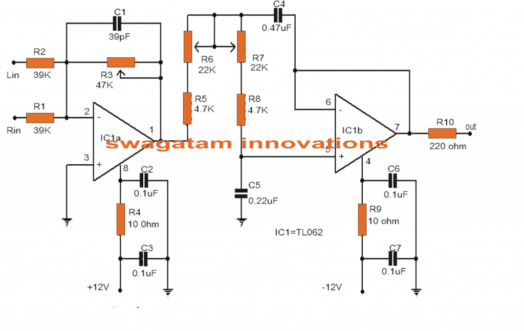
The circuit provided here utilizes the high efficiency opamp TL062 from ST Micro electronics. TL062 is a twin high input impedance J-FET opamp exhibiting minimal power consumption and large slew rate.
The opamp possesses outstanding digital attributes as well as being exceptionally compatible with this circuit.
Between the two opamps inside TLC062, one is connected in form of the mixer with pre amplifier stage. The left/right channels are linked to the inverting input of IC1a for mixing.
The gain of first stage may be tweaked utilizing POT R3.The output of the 1st stage is hooked up to the input of next stage via the filter circuit containing parts R5,R6,R7,R8,C4 and C5.
The second opamp (IC1b) functions as a buffer as well as the filtered output can be obtained at the pin 7 of the TLC062.
You may also want to read How to Build a High Power Subwoofer Amplifier
If you are interested to create your own low pass filter with a single IC 741 and customize it, then the following discussion might help!
Simple Active Low Pass Filter Circuit Using IC 741
In electronics, filter circuits are basically employed for restricting the passage of a certain frequency range while allowing some other band of frequency into the further stages of the circuit.
Types of Low Pass Filters
Primarily there are three types of frequency filters that are used for the above mentioned operations.
These are: Low pass filter, high pass filter and the band pass filter.
As the name suggests, a low pass filter circuit will allow all frequencies below a certain set frequency range.
A high pass filter circuit will allow only the frequencies which are higher than the preferred set range of frequency while a band pass filter will allow only an intermediate band of frequencies to flow to the next stage, inhibiting all frequencies which may be outside this set range of oscillations.
Filters are generally made with two types of configurations, the active type and the passive type.
Passive type filter are less efficient and involve complicated inductor and capacitor networks, making the unit bulky and undesirable.
However these will not require any power requirement for itself to operate, a benefit too small to be considered really useful.
Contrary to this active type of filters are very efficient, can be optimized to the point and are less complicated in terms of component count and calculations.
In this article we are discussing a very simple circuit of a low pass filter, which was requested by one of our avid readers Mr.Bourgeoisie.
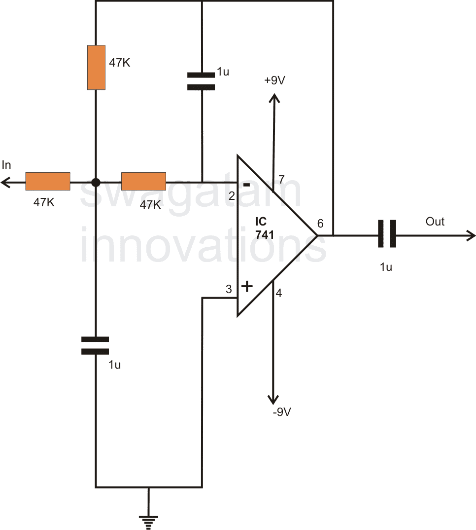
Looking at the circuit diagram we can see a very easy configuration consisting of a single opamp as the main active component.
The resistors and the capacitors are discretely dimensioned for a 50 Hz cut OFF, meaning no frequency above 50 Hz will be allowed to pass through the circuit into the output.
Circuit Diagram
Subwoofer Low Pass Filter using Transistors
The circuit diagram exhibits an active low-pass filter layout that can be assigned any preferred cut-off point, across a large range easily by computing a couple of magnitudes for four capacitors. The filter includes an RC -network and a pair of NPN/PNP BJTs.
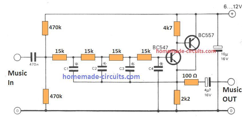
The transistor specifications shown could be straightaway substituted by some other varieties without altering the circuit's functionality. The supply voltage utilized must be between 6 and 12 V.
The capacitor values picked out for C1 to C4 establish the cut-off frequency. These magnitudes could be acquired from the below given two formulae:
C1 = C2 = C3 = 7.56 / fC
C4 = 4.46 / fC
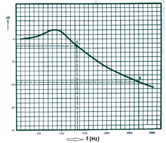
Here, fC provides the desired cut-off frequency (in Hertz). In this formula the amplitude response is down 3 dB, and the values for C1 to C4 are calculated in micro farads (If we use the unit in kHz, the result will be presented in nanofarad values and putting MHz will create picofarad units.) As an example the calculated effect is indicated for a filter constructed with C1 = C2 = C3 = 5n6 and C4 = 3n3.
The '-3 dB point' in this scenario develops at 1350 Hz. One octave greater, at 2700 Hz, the attenuation is already 19 dB.
For technical explanation of the circuit you may refer to the data provided here.
Deep Bass Generator using LM324 IC
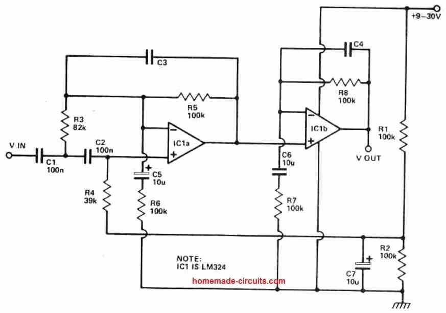
The well-known quad op-amp LM324 serves as the circuit's foundation. Four separate op amps of type 741 are included in this gadget.
It should be noted that they are capable of outputting 2V RMS of a 20 kHz sine wave without experiencing slew rate issues, which is more than enough to clip 99.99% of all known power amps.
These op amps' crossover distortion issues are solved by biasing their output stages into class A using R7 and R10.
A Butterworth second order filter made out of C1, C2, R3, and R6 eliminates all sounds below 2OHz, preventing amplifier overload from record warp signals.
The plateau in the circuit's response is created below the frequency set by the reactance of the capacitors by R5 and C2 working with R8 and C4. The deep bass generating circuit must be connected between the music source and the power amplifiers.

Questions & Answers
We can tell the value of C2 and C3 in deep boss generator circuit. Don’t know how to calculate the value from formula. Want to make low pass filter for 5200-1943 transistor based 200W mono amp board.
The Op amp selected has quite high noise at the frequencies levels for a sub. +50nV
This compares to the NE5532 for the same price with ~10 or the slightly more expensive alternatives eg. LM4562 with around 5.
I agree with you!
I’m not sure if this is the circuit that I’m am looking for. Years back I was into building subwoofers for home theater. And I can’t seem to find the article anymore but it talked about having a single 12 inch subwoofer with a long throw in great power handling capabilities in a sealed 12 x 12 x 12 box. With such a setup there was a circuit design for an active EQ cutting off everything above 50 hertz but a flying everything below 50 hertz on a specific curve that matched the frequency curve of the speaker in its box. Basically what it did was it Amplified low-frequency starting high amplification of 20 Hertz and as the increased the amplification decreased to match the Curve and gave it a flight line from 20 to 50 hertz. Power consumption was very large because the low frequencies required a lot so you needed a monster amp in a speaker that can handle quite a bit of power. I can’t seem to find this article anymore it was decades ago. Are you familiar with the build of the circuit? Do you know offhand if there’s any of them that are built that one could purchase or even just a circuit design that I can make? Thank you
I think you could try the following design. Although it is only 50 watt rated, the output transistors can be easily upgraded to produce much higher amplification:
https://www.homemade-circuits.com/build-this-subwoofer-amplifier-circuit-mini-ground-shaker/
Sir, how to cut off low frequency signals at an amplifier output? I mean b/w amplifier and speakers.
reduce input capacitor value of PA input stage to 100nF it will
Hi Aju, sorry I have no idea about it!
Sir,after integrating this low pass filter to an already working amplifier with base and trebble controls,will the controls still function as they used to? Or the whole amp output will be a bass amp? If so what can be done to have a distinction between bass and trebble in the same amp using the above filter idea?
Evans, you said you wanted a sub woofer filter, so the above is the recommended one…If you want both bass and treble then you will need the circuit which is explained in the following article
https://www.homemade-circuits.com/small-stereo-amplifier-circuit-with-bass-treble/
Got you
The above circuit require a dual power supply?
you can use the last circuit with a single supply also. Add a resistive divider at the junction of pin3 and C1. The resistive divider could be made using two 10K resistors in series, whose ends can be connected across +/0V of the supply.
Is it possible to get both high and low pass using this circuit for bass speaker and mid-range speaker? How?
With this C4,C5 R,5,6,7,8 Values the freq. range will be 18 to 105 HZ not 30 to 200Hz
Please I need an active filter for inverter circuit. Thanks
Sorry, I do not have the necessary calculation for it at the moment, I’ll try to get it if possible
dear sir
Low Pass Filter Circuit for Sub woofer
request answer please
1.The wattage of resistors quarter watt s enough?
2. 22k pot is dual gang stereo type?
3. What is the output woofer impedance and watt ? 4ohm 50w is enough ?
4. L in and R in lines other wire is connected with ground ?(input)
output other wire is taken from ground isnt it ?
Thank you sir
Dear Jayanth,
I think the R2 link must be removed, the input cannot be dual if the output is a single output.
So please ignore the R2 link
1) all resistors are 1/4 watt 5%
2) 22K pot is a dual ganged pot
3) impedance will depend on the type of amplifier used, it is not related to the above circuit
sir this circuit is working fine with 100w amp.but i want to increase the bass effect further more. for that what are the components and values to be change sir?
Hello jayanth, for customized design you can refer to the following article and adjust the values according to your preference
https://www.homemade-circuits.com/design-high-pass-filter-circuit-quickly/
R1 and R2 acts as a mixer of both L&R channels, its important when you are building a 2+1 system.
OK, but how can we get a stereo response using this circuit?
thanks for early reply sir
ok i will do same.
i will make this circuit recently and let you know sir.
Sure! Wish you all the best!
sir circuit is working perfectly. thanks
Glad it is working jayanth, keep up the good work!
help me I want to make metal detector wit high sensitivity. ( that is when ever it detects metal an indicator will glow only.) thanks in advance
sorry jack, I do not have any practical experience with metal detectors.
I need ur help I build a metal detector. wit 555 and it work but my problem is I need d out to be either high or low state. I even couple d o/p to op-amp no response. but there is variation in d 555 o/p .what I don’t like is that the sound is on always… *irritating * .help me out o
which circuit did you make?
Helo sir am thinking of building LA4440 combined with ka2206/tea2025 2.1 CH board where by 4440 is bridged to drive e a 4 inch 4 ohm subwoofer speaker and then Tea 2025 for mid speakers in stereo mode is this possible?I mean will 4440 be able to drive the 4″ 4 ohm bass speaker?
Hello Oliver, that looks possible to me.
Am planning to use a simple bass filter.1uf capacitor and 1k resistor
connected series at the input of 4440.is this the same as 4558 bass filter?
That might work, but the results may not be efficient, unless an op amp circuit is used
Do you have any simple 4558 bass filter that uses single 12vdc
Sorry, I do not seem to have a 4558 IC based bass filter circuit at this moment.
Do you have any other circuit apart 4558?
Yes there are a few designs using other opamps, you can find them here:
https://www.homemade-circuits.com/simple-tone-control-circuits/
what is d function dual pot of 22k? can I use the 10k, 50k,100k dual . *(sir or I can series 12k+ 10k)
it is probably for controlling the high frequency range, you can use 50 k pot or 10+12K pots in series.
Hai sir
In my area shop 0.47uf available only in 400v 474code….
Shall i use it sir…
Audio gain will be loss or not
Hi, Kesav, it will work but it will look quite bulky….anyway you can use it, audio will not get affected.
Thank u sir…
Sir one doubt…
I see one low pass filter circuit past 1 year back
Using 0.56uf , 0.47uf and 39nf..
In my area shop there is no 39nf till now…is there any alternate…while using alternate any effects will be loss or not..
Kesav, the capacitors in a filter circuit determine the range of the input frequency, if you change it the outcome might get affected…you can learn more about it here
https://www.homemade-circuits.com/2016/01/design-low-pass-filter-circuit-quickly.html
Very useful circuit, tryin' to build this one asap the only problem is lack of transistor 2N3905,, can i replace those bjt by two-parallel BC547?
What is that part of resistors r6 and r7?
those are pots….variable resistors