The discussed 2 simple IC 555 based emergency lamp system employs just a single IC 555 and yet is able to switch more than 20 LEDs directly, it will illuminate the LEDs only during the absence of mains power and ambient light.
1) Using IC 555 as a Comparator
The proposed circuit is not only simple, it offers some very useful feature without involving too many components.
The use of IC 555 facilitates direct connection of the LEds across it's output pin#3, without needing an extra transistor driver buffer stage, although it may be incorporated in case more number LEDs are desired.
The IC is also configured as a light detector and furthermore a DC inverter.
Light Detection
The design has two features, 1) Mains outage detection, 2) Day night detection.
Whenever mains fails or in case of an outage, the lamp quickly detects this and automatically switches ON, to provide an emergency illumination in the premise
The light detection feature ensures that the IC switches ON the LEDs only in the absence of adequate ambient light.
The level of darkness or the level of ambient light at which the IC triggers the LEDs may be set by adjusting the value of R2. This is an added feature which allows customizing the triggering threshold.
The introduction of C1 offers yet another novel feature to the design, it offers some delay before the LEDs are switched ON once the above specified conditions are met.
That means C2 can be selected for getting certain time delay before the LEDs get switched ON.
Last but not the least, the IC also provides the facility which prevents the LEDs from illuminating for so long the AC mains stays active.
The reset pin of the IC is held at zero potential by the T1 during the presence of AC mains, the moment mains power fails T1 switches OFF connecting the reset pin#4 to battery positive, so that the IC is reset for the required triggering.
Just forgot to mention, the circuit also behaves like a trickle charger and keeps the associated battery fully charged and in a standby condition whenever in need.
Caution: The circuit is not isolated from AC mains, so be extremely careful while testing.
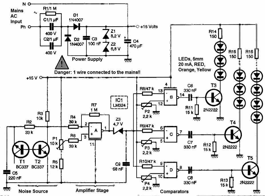
Circuit Diagram
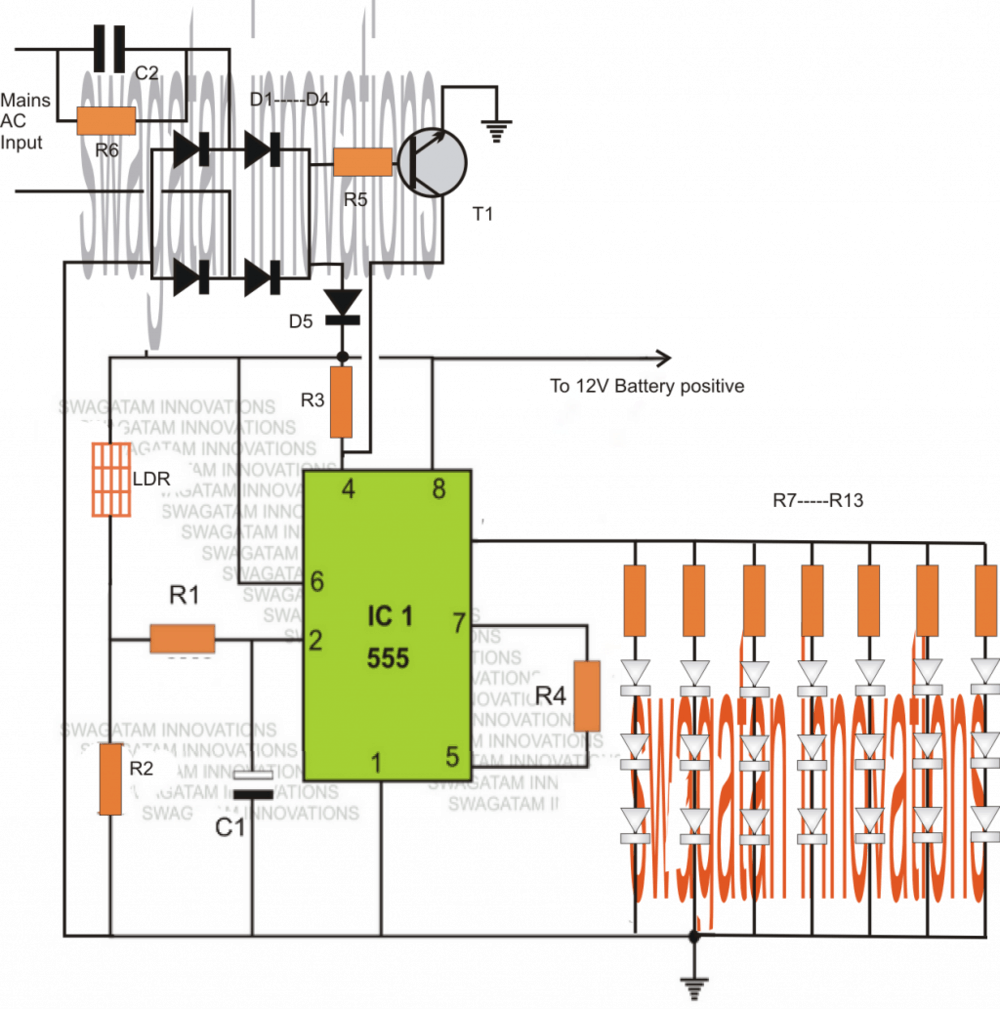
Parts List
R1 = 2M2
R2 = 1M
R3, R5 = 10K
R4, R6 = 120K
R7----R13 = 330 ohms
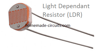
LDR = any standard type having ambient light resistance around 30K and dark resistance to infinity.
D1---D4 = 1N4007
C1 = As required
C2 = 0.22uF/400V
T1 = BC547
LEDs = white, high efficiency, 5mm
Battery = 12V, 4AH
IC 555 Pinouts

LDR Image
2) Using IC 555 Boost Converter
The following emergency light circuit uses a very common voltage boost converter concept for making a group of white LEDs illuminate at relatively lower power supplies.
I have explained how to make this interesting and useful little LED boost emergency light circuit.
Yet again we take the help of the evergreen work horse, the IC555 for implementing the proposed actions.
Using IC 555 as the Main Component
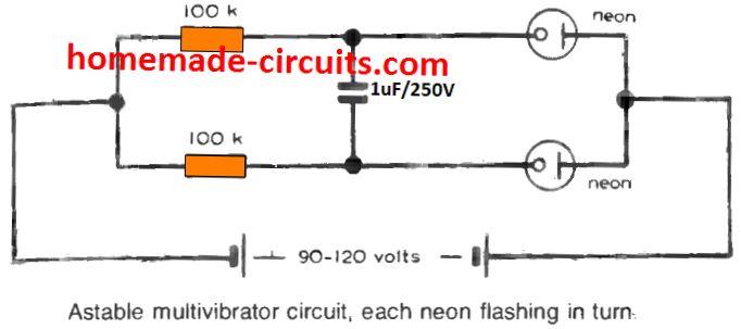
The figure shows a very simple circuit configuration where the IC 555 has been rigged as an astable multivibrator.
In an astable multivibrator design the various components are wired such that the output generates trains of pulses which are self sustaining and keeps coming as long as the circuit remains powered.
In the present configuration the output of the IC which is the pin #3 generates pulses at a frequency determined by the resistors R1 and R2 and also the capacitor C2.
R2 may be typically adjusted or made variable type for enabling dimming control of the LEDs.
However here the value of R2 has been fixed for acquiring optimum brightness from the LEDs.
The pulses available at pin#3 of the IC is used for ddriving the transistor T1 which in turn switches in response to the positive pulses.
The switching of the transistor pulls the supply voltage through the inductor in a pulsed mode.
As we know when alternating or pulsed voltage is applied across an inductor it tries to oppose the current and in the process kick an equivalent high voltage for compensating the applied current force.
This action of the inductor is what constitutes the boost action, where the voltage is stepped to higher levels than the actual supply voltage.
How L1 Functions
The above functioning of the inductor has been exploited in this circuit also.
L1 boosts the voltage in an attempt to restrict the applied AC, this high voltage generated across the coil during the non conducting phases of the transistor is fed across a series connected LEDs for illuminating them under lower current levels.
This process helps to illuminate the LEDs at relatively lower power consumption.
L1 winding is not so critical, it is a matter of little experimentation, the number of turns, wire guage, the diameter of the core, all are directly involved and affect the boost levels, therefore must be optimized carefully.
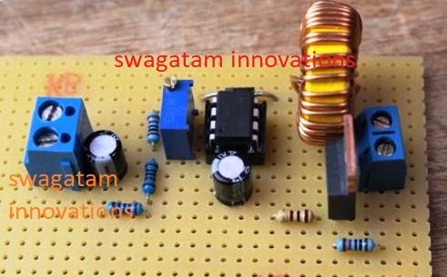
In the prototype I had used 50 turns of 22 SWG over an ordinary ferrite rod, which is normally used in small MW radio receivers.
The LEDs used by me were 1 watt, 350 mA types, however you may use different types if you want.
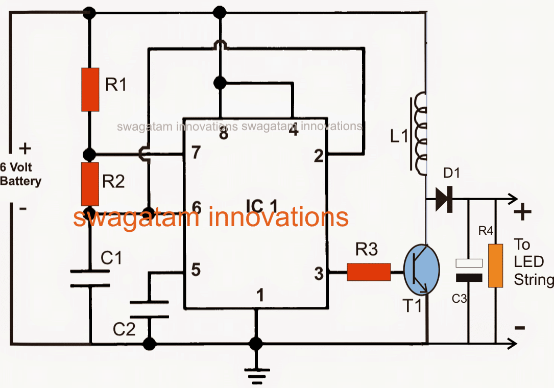
Parts List
R1 = 100K
R2 = 100k pot,
R3 = 100 Ohms,
R4 = 4k7, 1 watt
C1 = 680pF,
C2 = 0.01uF
C3 = 100uF/100V
L1 = see text
IC = LM555
T1 = TIP122
D1 = BA159
PLEASE CONNECT A 10 OHM RESISTOR IN SERIES WITH THE LED CHAIN FOR SAFEGUARDING IT FROM HIGH BOOSTED VOLTAGE.
INCREASING THE VALUE OF R2 SHOULD INCREASE THE BRIGHTNESS OF THE LEDs AND VICE VERSA.

Questions & Answers
Hi, thank you for the circuit.
I would like to place a battery maintainer/charger (1a) and place a big battery like 45A. To be able to light up some high power leds.
Could you please let me know if this will work?
Hi, yes it will work, just make sure to use a transistor at pin#3 of the IC for the driving the LEDs
Thanks for answering.
Another modification please.
Can be set to turn on the leds immediately (if dark) and not after some seconds.
Also what’s the battery charging voltage? It would be great if 13-13.8v?
Thanks in advance
You can remove the capacitor C1 if you don’t wish to have the delay….
Sir,
I have an old emergency light which is not working because of bad battery as well as burnt capacitor in the tranformerless supply circuit.Since I have some 18650 laptop cells of my old laptop,I want to use that in place of non working battery.can u plz suggest a circuit.
Led emergency lamp has
1. 24 Smd 2835 LEDs module with all in parallel
2.transformerless supply(capacitor burnt)
3.A battery
What I require?
1.Want to use 24 led module
2.use 18650 cells(I have 6 in no)
3. I have tp4056 charging module( if it can be used)
4.The circuit should have low voltage cutoff while discharging and high voltage cutoff while charging(I think tp4056 has high voltage cutoff feature)
Good backup
5.circuit should be powered with 5v mobile charger.
If there is cheaper and efficient circuit than tp4056 for charging above cells in the ckt plz tell .
Hi Nishant, You can try the circuit which is explained in the following article and see it that helps:
https://www.homemade-circuits.com/smart-emergency-lamp-circuit-with/
Hello sir. ..I was thinking of an emergency light bt not automatic… using a rechargeable battery and switch such that I can use it whenever I need… can u help me anyway?
Thank you. ..
Hello Deblina, please let me know the LED and the battery specifications so that I can calculate and suggest you the correct procedures…
what is the value of D5
1N4007
where to connect the -ve terminal of the battery
can you see the "earth" symbol…connect it there, the emitter of the transistor also needs to be made common with this line…
WHAT IS THE VALUE OF C1
a 10uF/25V will do
Thanks, if you are referring to the above circuit, it's already quite simple and uses minimum parts, anything less than this can make the design ineffective.
Good day Sir,
Please check some of the measurements i got when DC12V 4Ah is on and AC is turned off. Pin 3 is low ……..
PIN 2 12V
PIN 4 0.8V
PIN 6 10V
I think voltage at pin 6 and 2 are hindering pin 3 to become high
What is the Purpose of 120K from pin 5 to 7 …………..
that's great, thanks for the update!
thnx a lot …………….i disconnected the transistor from Pin 4……… rest of the cct is working fine ……………then i coupled ac cct again………with 12V 1amp transformer at I/P and capacitor filter at O/P of bridge………….its working fine………….
Pin4 should not be 0.8V it should be also near 10V….or equal to pin8 voltage…pin4 will be low only f the BC547 is conducting which will happen if AC mains is ON…
disconnect the link between the collector of the transistor and pin4 and then check the response
hi brother,
I made the whole cct ,but there is no output at o/p pin of 555 …….could u suggest what is the fault…………i made this cct in electronic workbench just to avoid fatigue
thnx and best regards for your nice work.
I am not sure why it may have happened because 0.22uF will not produce that much current to burn the 555……..anyway you can try adding a 4.7V/1watt zener across the bridge +/- pins, this will restrict the mains DC to this level.
The circuit doe not include an over charge cutout, if possible I will try to update it here.
Is this cct stop charging the battery ,once its fully charged??? if not ……could i add this feature and how ???
hello brother !!
sorry i was busy in job …….. whenever i got some time i tried different ccts from internet but they were all useless……..so to avoid fatigue i build a soft copy ……….
but there is a good news ……….ur ccts worked …….. yesterday i got time and assembled it on bread board………..its ok in absence of AC ……….but its showing no response when i turned on the AC supply……….BC547 was smoking so i replaced it ……but it didn't changed the result. plz guide….
I measured 12V on the reset Pin……………?? i think its not ok.
hi brother,
the circuit will work only when there's no AC mains, and complete darkness on the LDR…
by the way I did not understand what you meant by
."i made this cct in electronic workbench just to avoid fatigue"
what are the changes to be made for the circuit for using a 6V 5 Ah battery? if there are any changes needed. And is D5 also 1N4007?
use strings of two leds at the output with no series resistors, no other changes would be required.
yes D5 is also 1N4007
Sir can i use a 6V, 5Ah rechargeable battery to power the circuit given
yes it can be used
can i charged battery of 4.5v/1Ah with this circuit?
yes 4.5V/1ah can be charged
yes
where will i put the test probe in the circuit?
red at pin#4, black at ground.
did you make all the grounds common??
why, and what is transistor sage?
and by the way I already made this circuit.but i have a problem.
when i connected the battery and the 1 watt led to this circuit, and when i plugged in the cord to 220V ac, the 1 watt led didnt turnoff totally but instead it only dim a little. can you explain why? i havent put a transistor sage yet.
transistor keeps pin#4 of IC 555 to ground level (0V) which keeps the output of the IC inactive, check pin#4 voltage after switching ON mains power, it should show zero volts.
Read warning message in the article.
can i use 1 watt led here?
yes, by using a transistor sage at the output
what smaller battery do you mean? is like 12v/7.5Ah?
smaller batteries means batteries with lower voltages and current like, 4.5V/ 1ah
is this in trickle charging mode?
and what is trickle charging?
for smaller batteries this will be better tan trickle charging, but for larger battery it will be only work as trickle charger.
means it will only prevent the fully charged battery from self-discharging.
Sir i have a 0.47uF/400V metallised polyster capacitor instead of a 0.22uF/400V capacitor for C2 can i use that in my circuit…
Higher value will mean greater initial surge current, so that makes the circuit prone to damages, you can use it by adding some protections such as a thermister, a 1N4007 diode across C2 output and ground etc. or simply add two such capacitors in series.
Amazing project sir, sure to help loads of electronics hobbyists like me. Thankyou for this circuit.
Is the capacitor C2 a polyster or electrolytic capacitor? and what is the maximum number of LED's that can be used in this circuit. And in case i want to add a transistor buffer is it the same as in the street light circuit i.e.,collector to LED cathodes and emitter to ground?
Thanks Sriram,
C2 is metallized polyester.
The is can sink upto 150mA without issues so can accommodate LEDs within this limit.
Yes the transistor stage can be identical to the street light design.
If the peak voltage is 330v that means the battery is not safe at this kind of circuit??
by the way sorry for my misunderstanding. 🙂
330V will settle down to the required level due to low current levels from C2. you can add an additional zener diode if you feel so.
I just tested the capacitive reactance circuit a.k.a."transformerless power supply " you mentioned. When I touched the output at the bridge rectifier it gave me a SHOCK!!! but when I tested the current output it gives me only 100mA!. It can't even power a 12v/180mA comp. fan. Is that all normal???
Read the given caution statement, it's extremely dangerous to touch these circuits, even 5mA at 220V could kill a living being.
such power supplies are for low current applications only, your readings are correct and normal.