In this post I have explained how capacitive voltage divider circuits operate in electronic circuits, through formulas and solved examples.
By: Dhrubajyoti Biswas
What is a Voltage Divider Network
Talking about a voltage divider circuit, it is important to note that voltage in divider circuit gets equally distributed among all the existing components associated with the network, although the capacity may vary based upon the constitution of the components.
A voltage divider circuit can be built out of reactive components or even from fixed resistors.
However, when comparing to capacitive voltage dividers, the resistive dividers remain unaffected with the change of frequency in supply.
The purpose of this paper is to provide a detailed understanding of capacitive voltage dividers. But to gain more insight, it is vital to detail capacitive reactance and its effect on the capacitors at varied frequencies.
A capacitor is made of two conductive plates, placed parallel to each other which are additionally separated with an insulator. These two plates have one positive (+) and another negative (-) charge.
When a capacitor is charged fully via DC current, the dielectric [popularly referred to insulator] jams the current flow across the plates.
Another important characteristic of a capacitor in comparison to a resistor is: A capacitor stores energy on the conductive plates during charge, which the resistor does not, as it always tends to release out excess energy as heat.
But the energy stored by a capacitor is passed to the circuits that are connected with it during its discharge process.
This feature of a capacitor to store the charge is referred as reactance, and further referred as Capacitive Reactance [Xc] for which Ohm is the standard unit of measurement for reactance.
A discharged capacitor when connected to a DC power supply, the reactance remains low at the initial stage.
A substantial part of the current flows via the capacitor for a short span, which force the conductive plates get charged rapidly, and this eventually inhibits any further passage of current.
How Capacitor Blocks DC?
In a resistor, capacitor series network when the time period reaches a magnitude of 5RC, the conductive plates of the capacitor get fully charged, which signifies the charge received by the capacitor to be equal to the voltage supply, which stops any further current flow.
Furthermore, the reactance of the capacitor in this situation under the influence of the DC voltage reaches to max state [mega-ohms].
Capacitor in AC supply
In regard to using alternate current [AC] to charge a capacitor, wherein the AC current flow is always alternately polarized, the capacitor receiving the flow is subjected to a constant charging and discharging across its plates.
Now if we have constant current flow then we also need to determine the reactance value to restrict the flow.
Factors to determine value of capacitive resistance
If we take a look back on the capacitance we will find that the amount of charge on the conductive plates of a capacitor is proportional to the value of the capacitance and the voltage.
Now when a capacitor gets current flow from an AC input, the voltage supply goes through a constant change in its value, which invariably changes the value of the plates too proportionately.
Now let’s consider a situation where a capacitor contains higher value of capacitance.
In this situation the resistance R consume more time to charge the capacitor τ = RC. This implies that if the charging current is flowing for a longer span of time the reactance records a smaller value Xc, depending on the specified frequency.
Identically if the capacitance value is smaller in a capacitor, then to charge the capacitor it requires shorter RC time.
This shorter time causes the flow of current for a shorter span of time, which results in comparatively smaller reactance value, Xc.
Therefore, it is evident that with higher currents the value of the reactance remains small and vice versa.
And thus capacitive reactance is always inversely proportional to the capacitor’s capacitance value.
XC ∝ -1 C.
It is vital to note that capacitance is not the sole factor to analyze capacitive reactance.
With a low frequency of the AC voltage applied, the reactance gets more time develop based upon the allocated RC time constant. Further, it also blocks the current, indicating higher value of reactance.
Similarly, if the frequency applied is high, the reactance allows lesser time cycle for charging and discharging process to occur.
Moreover, it also receives higher current flow during the process, which leads to lower reactance.
So this proves that the impedance (AC reactance) of a capacitor and its magnitude is dependent on the frequency. Therefore, higher frequency results in lower reactance and vice versa, and thus it can be concluded that Capacitive Reactance Xc is inversely proportional to the frequency and capacitance.
The said theory of capacitive reactance can be summed up with the following equation:
Xc = 1/2πfC
Where:
· Xc = Capacitive Reactance in Ohms, (Ω)
· π (pi) = a numeric constant of 3.142 (or 22÷7)
· ƒ = Frequency in Hertz, (Hz)
· C = Capacitance in Farads, (F)
Capacitive Voltage Divider
This section will aim to provide a detailed explanation regarding how the frequency of supply affects two capacitors connected back to back or in series, better termed as capacitive voltage divider circuit.
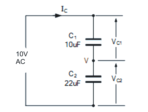
Capacitive Voltage Divider Circuit
To illustrate a capacitive voltage divider functioning, let us refer to the circuit above. Here, C1 and C2 are in series and connected to an AC power supply of 10 volts. Being in series both the capacitors are receiving same charge, Q.
However, the voltage will remain different and it is also dependent on the value of capacitance V = Q/C.
Considering Figure 1.0, the calculation of voltage across the capacitor can be determined through different ways.
One option is to find out the total circuit impedance and circuit current, i.e. to trace the value of capacitive reactance on each capacitor and then calculate the voltage drop across them. For instance:
EXAMPLE 1
As per Figure 1.0, with C1 and C2 of 10uF and 20uF respectively, calculate rms voltage drops occurring across the capacitor in a situation of sinusoidal voltage of 10 volts rms @ 80Hz.
C1 10uF Capacitor
Xc1 = 1/2πfC = 1/2π x 80 x 10uF x 10-6 = 200 Ohm
C2 = 20uF capacitor
Xc1 = 1/2πfC = 1/2π x 8000 x 22uF x 10-6 = 90
Ohm
Total Capacitive Reactance
Xc(total) = Xc1 + Xc2 = 200Ω + 90Ω = 290Ω
Ct = (C1 x C2) / (C1 + C2) = 10uF x 22uF / 10uF + 22uF = 6.88uF
Xc = 1/2πfCt = 1 / 1/2π x 80 x 6.88uF = 290Ω
Current in the circuit
I = E / Xc = 10V / 290Ω
The voltage serially drops for both the capacitor. Here the capacitive voltage divider is calculated as:
Vc1 = I x Xc1 = 34.5mA x 200Ω = 6.9V
Vc2 = I x Xc2 = 34.5mA x 90Ω = 3.1V
If the values of the capacitors differ, the smaller value capacitor can then charge to a higher voltage in comparison to the large value one.
In Example 1, the voltage charge recorded is 6.9 & 3.1 for C1 and C2 respectively. Now since the calculation is based on Kirchoff’s theory of voltage, therefore the total voltage drops for individual capacitor equals to the supply voltage value.
NOTE:
The voltage drop ratio for the two capacitors that is connected to series capacitive voltage divider circuit always remains same even if there is a frequency in supply.
Therefore as per Example 1, 6.9 and 3.1 volts are the same, even if the supply frequency is maximized from 80 to 800Hz.
EXAMPLE 2
How to find the capacitor voltage drop using the same capacitors used in Example 1?
Xc1 = 1/2πfC = 1/2π x 8000 x 10uF = 2 Ohm
Xc1 = 1/2πfC = 1/2π x 8000 x 22uF = 0.9 Ohm
I = V/Xc(total) = 10/2.9 = 3.45 Amps
Therefore, Vc1 = I x Xc1 = 3.45A x 2Ω = 6.9V
And, Vc2 = I x Xc2 = 3.45A x 0.9 Ω = 3.1V
As the voltage ratio remains same for both the capacitors, with increasing supply frequency, its impact is seen in the form of a decrease of combined capacitive reactance, as well as for total circuit impedance.
A reduced impedance causes higher flow of current, for instance, the circuit current at 80Hz is around 34.5mA, whereas at 8kHz there may be a 10 times increase of current supply, that is around 3.45A.
So it can be concluded that the flow of current via capacitive voltage divider is proportional to the frequency, I ∝ f.
As discussed above, the capacitive dividers which involve series of capacitors connected, they all drop AC voltage.
To find out the correct voltage drop the capacitive dividers take the value of capacitive reactance of a capacitor.
Therefore, it does not work as dividers for DC voltage, since in DC the capacitors arrest and block current, which causes nil current flow.
The dividers can be used in cases where the supply is driven by frequency.
There is a wide range of electronic use of capacitive voltage divider, from finger scanning device to Colpitts Oscillators. It is also preferred extensively as cheap alternate for mains transformer where capacitive voltage divider are employed to drop high mains current.


Comments
Hi Sawagatam;
Re. to your “bench power station” circuit.
I will use not analog but digital volt amp meter display. My transformer output is 24 V AC. So, i need about DC 12 volts or less for the display work voltage. I think 7812 regulator will may be overheated since transformer output is about DC 33 volts after capacitor filter.
So please advise if it is possible to use resistor or capacitor divider circuit or possible to use for instant 9V zener diode for the purpose?
Best Wishes
Hi Suat,
You can use a separate capacitive power supply along with a 7812 from the transformer secondary AC output as shown in the following figure:
https://www.homemade-circuits.com/wp-content/uploads/2023/05/capacitive-low-current-output-from-transformer-for-low-heat-on-7812.jpg
It is possible to use 7805 in the same circuit instead of 7812?
Regards
Yes that’s possible, as long as the bridge output voltage does not exceed 35V.
Swagatam;
I am unfamiliar with the capacitor under AC voltage. So I used 1 uF capacitor but its voltage capacity was higher than 100 volts that you offered so both 7812 and 7805 were burnt. Please advise if this approach is true or not?
Hi Suat,
The capacitor voltage represents the maximum tolerable voltage capacity of the capacitor, this has nothing to do with the output voltage. The output voltage will be exactly same as the input voltage. If your transformer is 30 V then the output from the capacitor will be also 30 V.
If you are saying that 7812 got burnt then it could be due to the input voltage exceeding 35 V. If the input voltage to the 7812 or 7805 is exceeding 35V then these ICs cannot be used.
Okey Swagatam;
How i made that mistake is unbelievable, i beg your pardon, since i had applied 220 volt. So the output voltage of the circuit you offered was too much for the 7812.
Now i understand what to do. Thank you very much.
No problem Suat,
Yes, you must use 24 V AC from the transformer, then the ICs might not burn. Please make sure that after rectification this voltage does not exceed 35 V.
All the best to you.
thanks for the precious info Swagatam.
However, what about if it would be 2 diodes instead of 4 diodes bridge rectifier.
You are welcome Suat,
Using 2 diodes is not possible, unless your transformer has 3 wires with center tap.