• Skip to main content
  • Skip to primary sidebar

Homemade Circuit Projects

Get free circuit help 24/7

New Projects | Privacy Policy | About us | Contact | Disclaimer | Copyright | Videos 

You are here: Home / Electronic Devices and Circuit Theory / What is Transistor Saturation

What is Transistor Saturation

Last Updated on September 5, 2021 by Swagatam Leave a Comment

In the previous post we learned BJT biasing, in this article we will learn what is transistor or BJT saturation and how to determine the value quickly through formulas and practical evaluations.

What is Transistor Saturation

The term saturation refers to any system where the specification levels have attained the maximum value.

A transistor may be said to be operating within its saturating area, when the current parameter reaches the maximum specified value.

We can take the example of a fully wet sponge, which may be in its saturated state when there's no space in it to hold any further liquid.

Adjusting the configuration may result in quickly changing the saturation level of the transistor.

Having said this, the maximum saturation level will be always as per the maximum collector current of the device as outlined in the datasheet of the device.

In transistors configurations it is normally ensured that the device does not reach its saturation point, since in this situation the base collector ceases to be in the reverse biased mode, causing distortions in the output signals.

We can see an operating point within the saturation region in the figure 4.8a. Observe that it is that specific region where the joint of the characteristic curves with the collector-to-emitter voltage is lower than VCEsat or at the same level. Also, the collector current is comparably high on the characteristic curves.

caution electricity can be dangerous

How to Calculate Transistor Saturation Level

By comparing and averaging the characteristic curves of Fig 4.8a and 4.8b, we are able to possibly achieve a quick method of determining the saturation level.

In Fig 4.8b we see the current level is relatively higher while the voltage level is at 0V. If we apply Ohm's law here, we are able to calculate the resistance between the collector and emitter pins of the BJT in the following manner:

A practical design implementation for the above formula can be seen in the fig 4.9 below:

This implies that whenever it is required to quickly evaluate the approximate saturation collector current for a given BJT in a circuit, you may simply assume an equivalent short circuit value across the collector emitter of the device and then apply it in the formula for getting the approximate collector saturation current. Put simply, assign VCE = 0V and then you can calculate VCEsat easily.

In circuits with fixed-bias configuration, as indicated in Fig 4.10 a short circuit could be applied, which may result in a voltage across RC equal to the voltage Vcc.

The saturation current developing in the above condition could be interpreted wit the following expression:

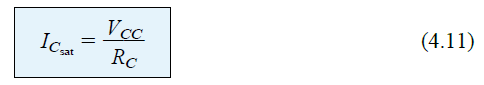
Solving a practical example to find the saturation current of a BJT:

If we compare the above result with the result that we acquired at the end of this post, we find that the result ICQ = 2.35mA is by far lower than the above 5.45mA which suggests that normally BJTs are never operated in the saturation level in circuits, rather at much lower values.

You'll also like:

  • 1.  Diac – Working and Application Circuits
  • 2.  What is beta (β) in BJTs
  • 3.  Understanding MOSFET Turn-ON Process
  • 4.  Emitter-Stabilized BJT Bias Circuit
  • 5.  DC Biasing in Transistors – BJTs
  • 6.  Diode Rectification: Half-Wave, Full-Wave, PIV

About Swagatam

I am an electronic engineer (dipIETE ), hobbyist, inventor, schematic/PCB designer, manufacturer. I am also the founder of the website: https://www.homemade-circuits.com/, where I love sharing my innovative circuit ideas and tutorials.
If you have any circuit related query, you may interact through comments, I'll be most happy to help!

Have Questions? Please Comment below to Solve your Queries! Comments must be Related to the above Topic!!

Subscribe
Notify of
0 Comments
Inline Feedbacks
View all comments

Primary Sidebar

Categories

  • 3-Phase Power (15)
  • 324 IC Circuits (19)
  • 4017 IC Circuits (52)
  • 4060 IC Circuits (26)
  • 555 IC Circuits (99)
  • 741 IC Circuits (20)
  • Arduino Engineering Projects (83)
  • Audio and Amplifier Projects (115)
  • Battery Chargers (83)
  • Car and Motorcycle (94)
  • Datasheets (73)
  • Decorative Lighting (Diwali, Christmas) (33)
  • Electronic Components (101)
  • Electronic Devices and Circuit Theory (36)
  • Electronics Tutorial (120)
  • Fish Aquarium (5)
  • Free Energy (34)
  • Fun Projects (13)
  • GSM Projects (9)
  • Health Related (20)
  • Heater Controllers (29)
  • Home Electrical Circuits (103)
  • How to Articles (20)
  • Incubator Related (6)
  • Industrial Electronics (28)
  • Infrared (IR) (40)
  • Inverter Circuits (98)
  • Laser Projects (12)
  • LED and Light Effect (93)
  • LM317/LM338 (21)
  • LM3915 IC (25)
  • Meters and Testers (66)
  • Mini Projects (149)
  • Motor Controller (67)
  • MPPT (7)
  • Oscillator Circuits (26)
  • PIR (Passive Infrared) (8)
  • Power Electronics (34)
  • Power Supply Circuits (79)
  • Radio Circuits (10)
  • Remote Control (48)
  • Security and Alarm (62)
  • Sensors and Detectors (121)
  • SG3525 IC (5)
  • Simple Circuits (75)
  • SMPS (29)
  • Solar Controllers (61)
  • Timer and Delay Relay (53)
  • TL494 IC (5)
  • Transformerless Power Supply (8)
  • Transmitter Circuits (41)
  • Ultrasonic Projects (16)
  • Water Level Controller (45)

Calculators

  • AWG to Millimeter Converter
  • Battery Back up Time Calculator
  • Capacitance Reactance Calculator
  • IC 555 Astable Calculator
  • IC 555 Monostable Calculator
  • Inductance Calculator
  • LC Resonance Calculator
  • LM317, LM338, LM396 Calculator
  • Ohm’s Law Calculator
  • Phase Angle Phase Shift Calculator
  • Power Factor (PF) Calculator
  • Reactance Calculator
  • Small Signal Transistor(BJT) and Diode Quick Datasheet
  • Transistor Astable Calculator
  • Transistor base Resistor Calculator
  • Voltage Divider Calculator
  • Wire Current Calculator
  • Zener Diode Calculator

© 2023 · Swagatam Innovations

wpDiscuz