In this post I have explained a four simple yet a safe way of charging a Li-ion battery using ordinary ICs like LM317 and NE555 which can be easily constructed at home by any new hobbyist.
Although Li-Ion batteries are vulnerable devices, these can be charged through simpler circuits if the charging rate does not cause significant warming of the battery., and if the user does not mind a slight delay in the charging period of the cell.
For users who want rapid charging of the battery, must not use the below explained concepts, instead they can employ one of these professional smart designs.
Basic Facts about Li-Ion Charging
Before learning the construction procedures of a li-Ion Charger, it would be important for us to know the basic parameters concerned with the charging Li-Ion battery.
Unlike, lead acid battery, a Li-Ion battery can be charged at significantly high initial currents which can as high as the Ah rating of the battery itself. This is termed as charging at 1C rate, where C is the Ah value of the battery.
Having said this, it is never advisable to use this extreme rate, as this would mean charging the battery at highly stressful conditions due to increase in its temperature. A 0.5C rate is therefore considered as a standard recommended value.
0.5C signifies a charging current rate that's 50% of the Ah value of the battery. In tropical summer conditions, even this rate can turn into an unfavorable rate for the battery due to the existing high ambient temperature.
Does Charging a Li-Ion Battery Require Complex Considerations?
Absolutely not. It's actually an extremely friendly form of battery, and will get charged with minimal considerations, although these minimal considerations are essential and must be followed without fail.
A few critical but easy to implement considerations are: auto cut-off at the full charge level, constant voltage, and constant current input supply.
The following explanation will help to understand this better.
The following graph suggests the ideal charging procedure of a standard 3.7 V Li-Ion Cell, rated with 4.2 V as the full charge level.
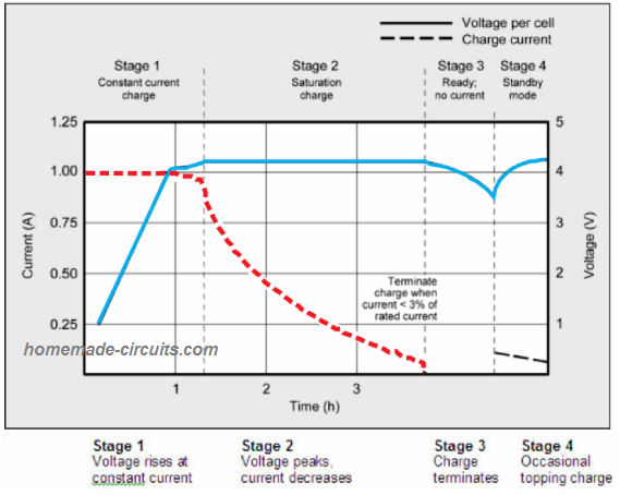
Stage#1: At the initial stage#1 we see that the battery voltage rises from 0.25 V to 4.0 V level in around one hour at 1 amp constant current charging rate. This is indicated by the BLUE line. The 0.25 V is only for indicative purpose, an actual 3.7 V cell should never be discharged below 3 V.
Stage#2: In stage#2, the charging enters the saturation charge state, where the voltage peaks to the full charge level of 4.2 V, and the current consumption begins dropping. This drop in the current rate continues for the next couple of hours. The charging current is indicated by the RED dotted line.
Stage#3: As the current drops, it reaches its lowest level which is lower than 3% of the cell's Ah rating.
Once this happens, the input supply is switched OFF and the cell is allowed to settle down for another 1 hour.
After one hour the cell voltage indicates the real State-Of-Charge or the SoC of the cell. The SoC of a cell or battery is the optimal charge level which it has attained after a course of full charging, and this level shows the actual level which can be used for a given application.
At this state we can say the cell condition is ready to use.
Stage#4: In situations where the cell is not used for long periods, a topping up charging is applied from time to time, wherein the current consumed by the cell is below 3% of its Ah value.
Remember, although the graph shows the cell being charged even after it has reached 4.2 V, that's strictly not recommended during practical charging of a Li-Ion cell. The supply must be automatically cut off as soon as the cell reaches 4.2 V level.
So What does the Graph Basically Suggest?
- Use an input supply which has a fixed current and fixed voltage output, as discussed above. (Typically this can be = Voltage 14% higher than printed value, Current 50% of the Ah value, lower current than this will also work nicely, although charging time will increase proportionately)
- The charger should have an auto-cut off at the recommended full charge level.
- Temperature management or control for the battery may not be required if the input current is restricted to a value which does not cause warming of the battery
If you don't have an auto cut-off, simply restrict the constant voltage input to 4.1 V.
1) Simplest Li-Ion Charger using a single MOSFET
If you are looking for a cheapest and the simplest Li-Ion charger circuit, then there cannot be a better option than this one.
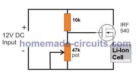
A single MOSFET, a preset or trimmer and a 10k ohm 1/4 watt resistor is all that you would need to make a simple and safe charger circuit.
Before connecting the output to a Li-Ion cell make sure of a couple of things.
1) Since the above design does not incorporate temperature regulation, the input current must be restricted to a level which does not cause significant heating of the cell.
2) Adjust the preset to generate exactly a 4.1V across the charging terminals, where the cell is supposed to be connected. A great way to fix this voltage is to connect a precise zener diode in place of the preset, and replace the 10 k ohm with a 1 k ohm resistor.
For the current, typically a constant current input of around 0.5C would be just right, that is 50% of the mAh value of the cell. So, the input supply should have a fixed 12V DC and a current that is 50% of the Li-Ion cells mAH rating.
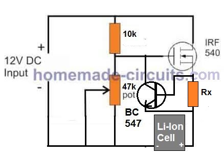
Adding a Current Controller
If the input DC supply source is not current controlled, in that case we can quickly upgrade the above circuit with a simple BJT current control stage as shown below:
Advantage of Li-Ion Battery
The main advantage with Li-Ion cells is their ability to accept charge at a quick, and an efficient rate. However Li-Ion cells have the bad reputation of being too sensitive to unfavorable inputs such as high voltage, high current, and most importantly over charging conditions.
When charged under any of the above conditions, the cell may get too warm, and if the conditions persist, may result in leaking of the cell fluid or even an explosion, ultimately damaging the cell permanently.
Under any unfavorable charging conditions the first thing that happens to the cell is rise in its temperature, and in the proposed circuit concept we utilize this characteristic of the device for implementing the required safety operations, where the cell is never allowed to reach high temperatures keeping the parameters well under the required specs of the cell.
2) Using LM317 as the Controller IC
In this blog we have come across many battery charger circuits using the IC LM317 and LM338 which are the most versatile, and the most suitable devices for the discussed operations.
Here too we employ the IC LM317, although this device is used only to generate the required regulated voltage, and current for the connected Li-Ion cell.
The actual sensing function is done by the couple of NPN transistors which are positioned such that they come in physical contact with the cell under charge.
Looking at the given circuit diagram, we get three types of protections simultaneously:
When power is applied to the set up, the IC 317 restricts, and generates an output equal to 3.9V to the connected Li-ion battery.
- The 640 ohm resistor makes sure this voltage never exceeds the full charge limit.
- Two NPN transistors connected in a standard Darlington mode to the ADJ pin of the IC controls the cell temperature.
- These transistors also work like current limiter, preventing an over current situation for the Li-Ion cell.
We know that if the ADJ pin of the IC 317 is grounded, the situation completely shuts off the output voltage from it.
It means if the transistors conduct would cause a short circuit of the ADJ pin to ground causing the output to the battery shut off.
With the above feature in hand, here the Darlingtom pair does a couple of interesting safety functions.
The 0.8 resistor connected across its base and ground restricts the max current to around 500 mA, if the current tends to exceed this limit, the voltage across the 0.8 ohm resistor becomes sufficient to activate the transistors which "chokes" up the output of the IC, and inhibits any further rise in the current. This in turn helps keep the battery from getting undesired amounts of current.
Using Temperature Detection as the Parameter
However, the main safety function that's conducted by the transistors is detecting the rise in temperature of the Li-Ion battery.
Transistors like all semiconductor devices tend to conduct current more proportionately with increase in the ambient or their body temperatures.
As discussed, these transistor must be positioned in close physical contact with the battery.
Now suppose in case the cell temperature begins rising, the transistors would respond to this and start conducting, the conduction would instantly cause the ADJ pin of the IC to be subjected more to the ground potential, resulting in decrease in the output voltage.
With a decrease in the charging voltage the temperature rise of the connected Li-Ion battery would also decrease. The result being a controlled charging of the cell, making sure the cell never goes into a run away situations, and maintains a safe charging profile.
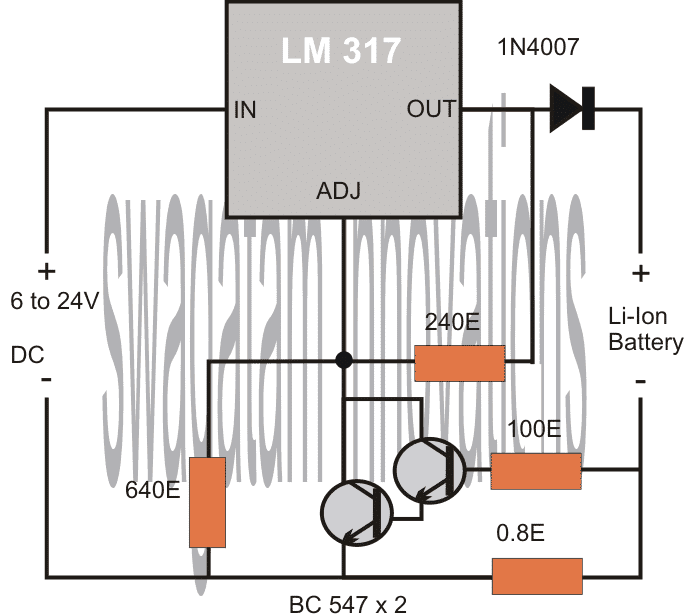
The above circuit works with temperature compensation principle, but it does not incorporate an automatic over charge cut off feature, and therefore the maximum charging voltage is being fixed at 4.1 V.
Without Temperature Compensation
If you want to avoid the temperature controlling hassles, you can simply ignore the Darlington pair of BC547, and use a single BC547 instead.
Now, this will work only as a current/voltage controlled supply for the Li-Ion cell. Here's the required modified design.
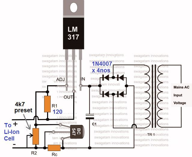
Since, here temperature control is not employed, make sure that Rc value is correctly dimensioned for a 0.5 C rate. For this you can use the following formula:
Rc = 0.7 / 50% of Ah value
Suppose the Ah value is printed as 2800 mAh. Then the above formula could be solved as:
Rc = 0.7 / 1400 mA = 0.7 / 1.4 = 0.5 Ohms
Wattage will be 0.7 x 1.4 = 0.98, or simply 1 watt.
Likewise, make sure the 4k7 preset is adjusted to an exact 4.1 V across the output terminals.
Once the above adjustments are made, you can charge the intended Li-Ion battery safely, without worrying about any untoward situation.
Since, at 4.1 V we cannot assume the battery to be fully charged.
To counter the above drawback, an automatic cut off facility becomes more favorable than the above concept.
I have discussed many op amp automatic charger circuits in this blog, any one of them can be applied for the proposed design, but since we are interested to keep the design cheap and easy, an alternative idea which is shown below can be tried.
Employing an SCR for the Cut-Off
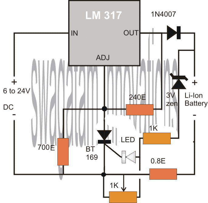
If you are interested to have an auto cut off only, without temperature monitoring, you can try the below explained SCR based design. The SCR is used across the ADJ and ground of the IC for a latching operation. The gate is rigged with the output such that when the potential reaches at about 4.2V, the SCR fires and latches ON, cutting of power to the battery permanently.
The threshold may be adjusted in the following manner:
Initially keep the 1K preset adjusted to ground level (extreme right), apply a 4.3V external voltage source at the output terminals.
Now slowly adjust the preset until the SCR just fires (LED illuminated).
This sets the circuit for the auto shut off action.
How to Set-Up the Above Circuit
Initially keep the central slider arm of the preset touching the ground rail of the circuit.
Now, without connecting the battery switch ON power, check the output voltage which would naturally show the full charge level as set by the 700 ohm resistor.
Next, very skilfully and gently adjust the preset until the SCR just fires shutting off the output voltage to zero.
That's it, now you can assume the circuit to be all set.
Connect a discharged battery, switch ON power and check the response, presumably the SCR will not fire until the set threshold is reached, and cut off as soon as the battery reaches the set full charge threshold.
3) Li-Ion Battery Charger Circuit Using IC 555
The second simple design explains a straightforward yet precise automatic Li-Ion battery charger circuit using the ubiquitous IC 555.
Charging Li-ion Battery Can be Critical
A Li-ion battery as we all know needs to be charged under controlled conditions, if it's charged with ordinary means could lead to damage or even explosion of the battery.
Basically Li-ion batteries don't like over charging their cells. Once the cells reach the upper threshold, the charging voltage should be cut off.
The following Li-Ion battery charger circuit very efficiently follows the above conditions such that the connected battery is never allowed to exceed its over charge limit.
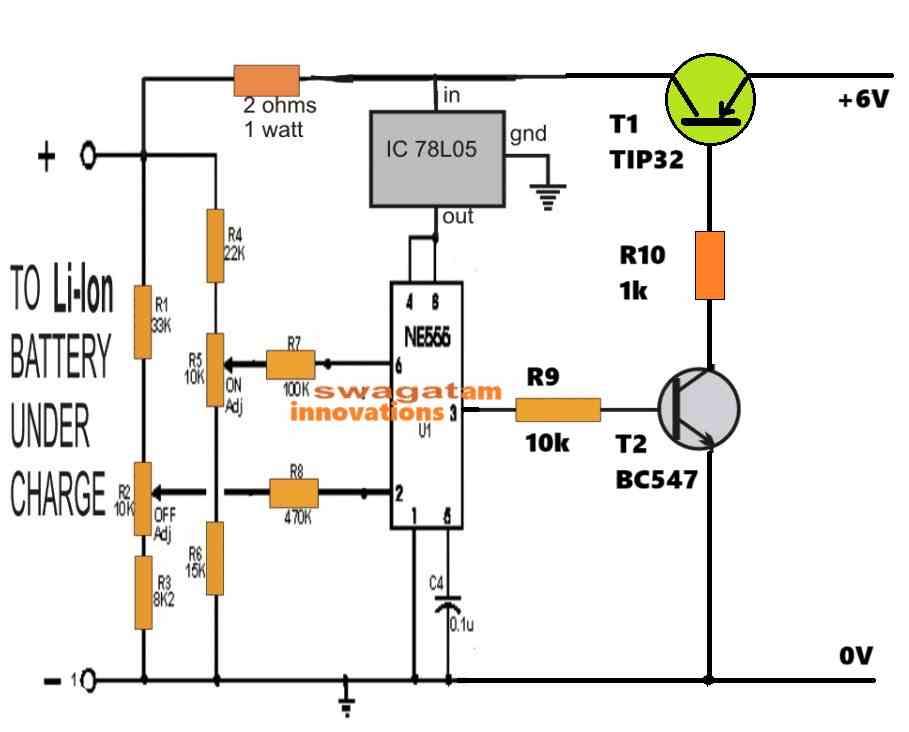
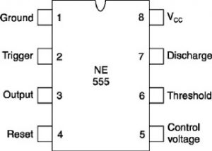
When the IC 555 is used as a comparator, its pin#2 and pin#6 become effective sensing inputs for detecting the lower and the upper voltage threshold limits depending upon the setting of the relevant presets.
Pin#2 monitors the low voltage threshold level, and triggers the output to a high logic in case the level drops below the set limit.
Conversely, pin#6 monitors the upper voltage threshold and reverts the output to low on detecting a voltage level higher than the set high detection limit.
Basically the upper cut off and lower switch ON actions must be set with the help of the relevant presets satisfying the standard specs of the IC as well as the connected battery.
The preset concerning pin#2 must be set such that the lower limit corresponds to 1/3rd of the Vcc, and similarly preset associated with pin#6 must be set such that the upper cut off limit corresponds to 2/3rd of Vcc, as per the standard rules of the IC 555.
How it Works
The entire functioning of the proposed Li-Ion charger circuit using IC 555 takes place as explained in the following discussion:
Let's Assume a fully discharged li-ion battery (at around 3.4V) is connected at the output of the below shown circuit.
Assuming the lower threshold to be set somewhere above the 3.4V level, pin#2 immediately senses the low voltage situation and pulls the output high at pin#3.
The high at pin#3 activates the transistor which switches ON the input power to the connected battery.
The battery now gradually begins charging.
As soon as the battery reaches full charge (@4.2V), assuming the upper cut off threshold at pin#6 to be set at around 4.2v, the level is sensed at pin#6 which immediately reverts the output to low.
The low output instantly switches off the transistor which means the charging input is now inhibited or cut off to the battery.
The inclusion of a transistor T1 stage provides the facility of charging higher current Li-Ion cells also.
The power supply must be selected with voltage not exceeding 6V, and current rating 1/2th of battery Ah rating.
Circuit Diagram
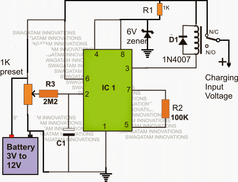
If you feel that the above design is much complex you could try the following design which looks much simpler:
How to Set up the Circuit
Connect a fully charged battery across the shown points and adjust the preset such that the relay just deactivates from N/C to N/O position....do this without connecting any charging DC input to the circuit.
Once this is done you can assume the circuit to be set and usable for an automatic battery supply cut off when fully charged.
During actual charging, make sure the charging input current is always lower than the battery AH rating, meaning if suppose the battery AH is 900mAH, the input should not be more than 500mA.
The battery should be removed as soon as the relay switches OFF to prevent self discharging of the battery via the 1K preset.
IC1 = IC555
All resistors are 1/4 watt CFR
IC 555 Pinout
Conclusion
Although the designs presented above are all technically correct and will perform the tasks as per the proposed specifications, they actually appear as an overkill.
A simple yet effective and safe way to charge a Li-Ion Cell is explained in this post, and this circuit may be applicable to all forms of batteries since it perfectly takes care of two crucial parameters: Constant-Current and full charge auto cut-off. A constant voltage is assumed to be available from the charging source.
4) Charging Many Li-Ion Batteries
The article explains a simple circuit which can be used for charging at least 25 nos of Li-Ion cells in parallel together quickly, from a single voltage source such as a 12V battery or a 12V solar panel.
The idea was requested by one the keen followers of this blog, let's hear it :
Charging many Li-ion Battery Together
Can you help me design a circuit to charge 25 li-on cell battery (3.7v- 800mA each) at the same time. My power source is from 12v- 50AH battery. Also let me know how many amps of the 12v battery would be drawn with this setup per hour...thanks in advance.
The Design
When it comes to charging, Li-ion cells require more stringent parameters compared to lead acid batteries.
This becomes especially crucial because Li-ion cells tend to generate considerable amount of heat in the course of the charging process, and if this heat generation goes beyond control may lead serious damage to the cell or even a possible explosion.
However one good thing about Li-ion cells is that they can be charged at full 1C rate initially, contrary to lead acid batteries which doesn't allow more than C/5 charging rate.
The above advantage permits Li-ion cells to get charged at 10 times faster rate than the lead acid counter part.
As discussed above, since heat management becomes the crucial issue, if this parameter is appropriately controlled, the rest of the things become pretty simple.
It means we can charge the Li-ion cells at full 1C rate without being bothered about anything as long as we have something which monitors the heat generation from these cells and initiates the necessary corrective measures.
I have tried to implement this by attaching a separate heat sensing circuit which monitors the heat from the cells and regulates the charging current in case the heat starts deviating from safe levels.
Controlling Temperature at 1C Rate is Crucial
The first circuit diagram below shows a precise temperature sensor circuit using the IC LM324. Three of its opamps have been employed here.
The diode D1 is a 1N4148 which effectively acts as the temperature sensor here. The voltage across this diode drops by 2mV with every degree rise in temperature.
This change in the voltage across D1 prompts A2 to change its output logic, which in turn initiates A3 to gradually increase its output voltage correspondingly.
The output of A3 is connected to an opto coupler LED. As per the setting of P1, A4 output tends to increase in response to the heat from the cell, until eventually the connected LED lights up and the internal transistor of the opto conducts.
When this happens the opto transistor supplies the 12V to the LM338 circuit for initiating the necessary corrective actions.
The second circuit shows a simple regulated power supply using the IC LM338. The 2k2 pot is adjusted to produce exactly 4.5V across the connected Li-ion cells.
The preceding IC741 circuit is an over charge cut off circuit which monitors the charge over the cells and disconnects the supply when it reaches above 4.2V.
The BC547 at the left near the ICLM338 is introduced for applying the appropriate corrective actions when the cells begin getting hot.
In case the cells begin getting too hot, the supply from the temperature sensor opto coupler hits the LM338 transistor (BC547), the transistor conducts, and instantly shuts off the LM338 output until the temperature comes down to normal levels, this process continues until the cells get fully charged when the IC 741 activates and disconnects the cells permanently from the source.
In all 25 cells may be connected to this circuit in parallel, each positive line must incorporate a separate diode and a 5 Ohm 1 watt resistor for equal distribution of charge.
The entire cell package should be fixed over a common aluminum platform so that the heat is dissipated over the aluminum plate uniformly.
D1 should be glued appropriately over this aluminum plate so that the dissipated heat is optimally sensed by the sensor D1.
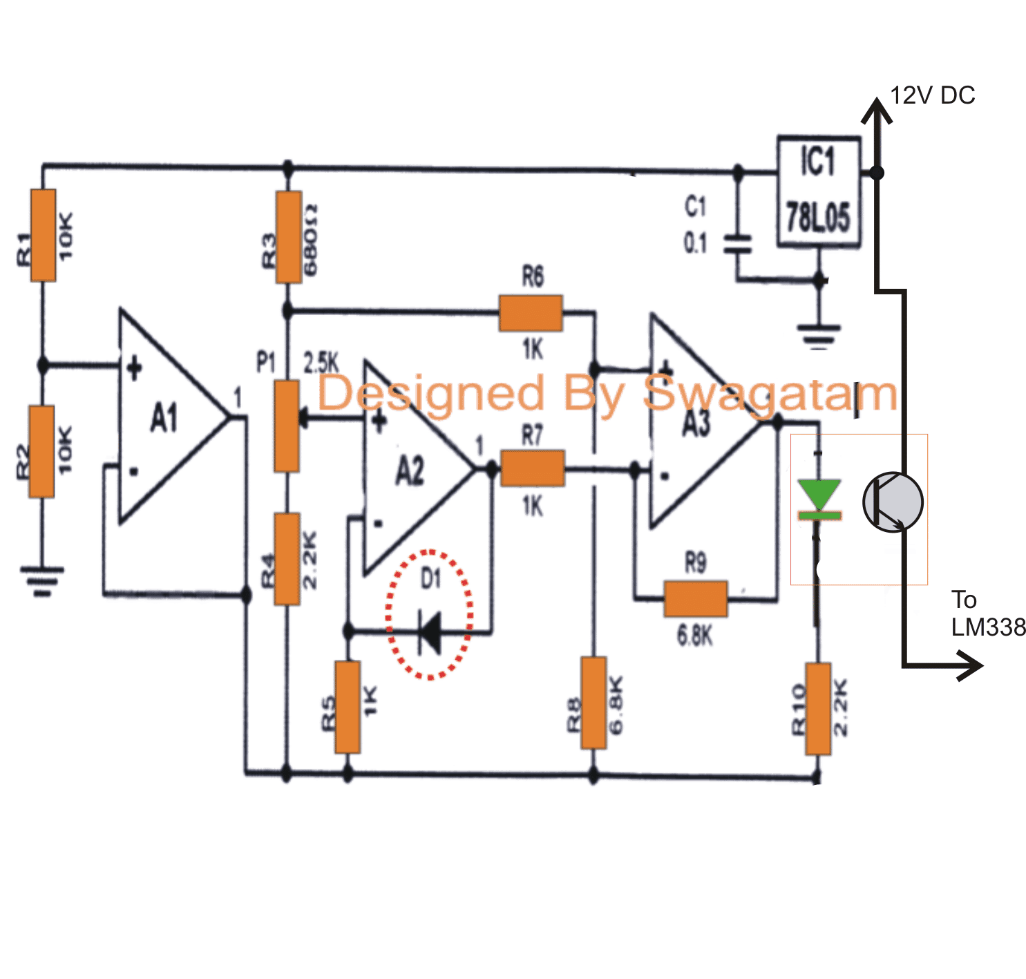
Automatic Li-Ion Cell Charger and Controller Circuit.
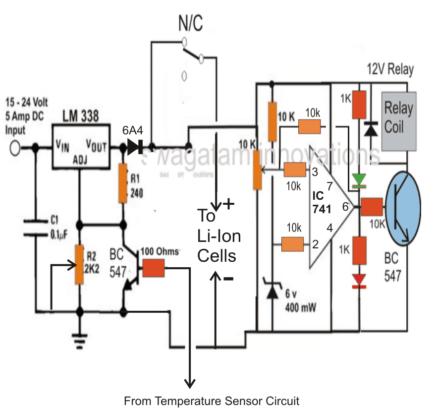
Conclusion
- The basic criteria that needs to be maintained for any battery are: charging under convenient temperatures, and cutting off the supply as soon as it reaches the full charge. That's the basic thing you need to follow regardless of the battery type. You can monitor this manually or make it automatic, under both cases your battery will charge safely and have a longer life.
- The charging/discharging current is responsible for the temperature of the battery, if these are too high compared to the ambient temperature then your battery will suffer heavily in the long run.
- Second important factor is never allowing the battery to discharge heavily. Keep restoring the full charge level or keep topping it up whenever possible. This will ensure that the battery never reaches its lower discharge levels.
- If you find it difficult to monitor this manually then you can go for an automatic circuit as described on this page.
Have further doubts? Please let them come through the comment box below 🙂



Questions & Answers
BT169 is a standard ScR very popular one, you will get it.
Please first confirm the above circuit and then we can go ahead with the LED indications….please note that this circuit is not confirmed yet, so the functions may not be guaranteed.
Hi Swagatam
Thanks for the interesting simple yet safe Lithium battery charger circuit. Recently I acquired some 4.2 volt 4200 mAh lithium ion batteries (size TR18650) but am planning to build my own charger. Your max voltage goes up to 3.9v, but how does one go about safely charging the newer 4.2 v cells ? Any modifications needed to your circuit to achieve this ? Regards, J.
Hi J, thanks,
Do not use the above circuit as it's not yet verified, you can try the SECOND one from the link below, it's a bit elaborate but it's safer and accurate, moreover you can adjust it to suit any desired voltage level:
https://www.homemade-circuits.com/2012/07/make-6v-4ah-automatic-battery-charger.html
I want to make a circuite have output 17.4v – 210mA to charge 4 lithium-ion cell ! Can I follow this circuit ??
the above circuit will need to be tweaked a lot for exact results, you can try the second circuit from the following link
For R2 use a 10k pot for adjusting 17.4V output
https://www.homemade-circuits.com/2012/07/make-6v-4ah-automatic-battery-charger.html
Hi Swagat,
Can we modify this circuit for charging 11.1Volt, 6600mAh Li-Ion battery. Or do you have any recommended circuit for this.
Thanks
Hi Arun,
yes the above circuits can modified for the specified application…… the second design by selecting the zener diode suitably.
Is the second one to be declared stable now? I need it to connect my 3,7 Lithion battery to a 6V solar panel.
I want to minimize the components, so if I can remove the pot and change the zener to a 4007 it would be great. Also removing the LED and connect the SCR to the ground. Right?
according to me it's perfect, although I haven't checked it practically.
Hi Sawgat,
I am trying to implement the battery charger circuit for a 12v 2.8Ah, (though i will be using 3 batteries in parallel to achieve the required voltage).
say by selecting a 10 V zener wil i be able to achieve the same??
Thanks
Yeshwanth Kumar J
Hi Yeshwanth, yes it can be implemented by using a 10V zener and setting the preset appropriately, also the 700 ohm resistor will need to calculated and replaced for getting the required 14V output for charging the 12V batt.
The input current must not be much higher than 1/10th of the battery AH for correct response.
The circuit has not been verified practically by me, though.
thanks Swagat
I have another doubt what is the use of 240 ohm resistor that i connected from the output to the scr? And can you help me out with the calculation of the 700 ohm resistor? If you can just guide me through it will be of great help to me.
Thanks
Yeshwanth Kumar J
Thanks for your prompt response
I have a few doubts You said adjust the 1k to preset? what do you mean by this? Also can you help me out with the calculation realted to the selection of 700OHm resistor?
Thanks
Yeshwanth Kumar J
Yeshwant, 240 ohms is as per the datasheet of the LM317, it's mandatory and fixed.
For finding the 700 ohm resistor replacement, you can use any online LM317 calculator software.
Just enter the 240 value and the required output voltage in the given slots and press calculate to get the value in question.
……….I'll update the setting procedure of the preset soon in the above article
Thanku Swagatam it will be of great help to me, to understand my working better. Once again thanku waiting for your response
Regards
yeshwanth Kumar J
You are welcome Yeshwanth,
the required data has been updated in the article, please check it.
Thanku Swagatam. I just realized one more thing, Once i trigger the SCR its not possible to switch off my SCR. Which means i cannot charge my battery again with out disconnecting my battery. ( I am trying to use this system as a nano UPS to power up Hard disks). Is there any other better way for me to do this??
Thanks
Yeshwanth Kumar J
What is the purpose of 0.8 ohm resistor? Is it for current limiting? If so, how it limits current?
It limits current through Ohms law I = V/R
Hello sir,
can this circuit control discharging of battery?
please elaborate, I could not understand the requirement
Hello;
What would be the changing required in circuit if i want to charge a 4.2V,1200mAH cylindrical battery with overcharge and over discharge protection.Over discharge in sense if battery is connected with circuit and their is no power supply attached the battery will drain through the circuitry..
Also it should have 3 status LED's for charging yellow,full charge green and for fault indication red if battery is dead or short circuited.Please reply i am hoping for good.
I have addressed your requirement in the following article, please check it out:
https://www.homemade-circuits.com/2015/03/battery-charging-fault-indicator-circuit.html
Hello sir, I'm a student and currently doing my final project. What would be charging circuit if i want to charge a 4.2V,30000mAH lithium ion battery with overcharge and over discharge protection too. i hope you can help me. Thanks.
Hello Abby, may be you can try the following concept for your need:
https://www.homemade-circuits.com/2015/10/smart-emergency-lamp-circuit-with.html
Sir , i have tried the 2nd ckt many times, with scr 1k pot& 3.9v zener.
Whenever i connected the fully charged batt from mobile(3.7v) and adjusted pot led never lights
when i disconnected connection between the led and pot terminal its lighting the led.
actually one the 2 terminals of pot(left + adj) is connected to -ve and the 3rd terminal or right
is connected to led's positive lead so its a chance of short circuiting?
Rohith, you will need to use a preset (not pot) and adjust it very carefully for getting the results, if you are finding it difficult then you can try an opamp based circuit which is much reliable, as shown below
https://www.homemade-circuits.com/2012/02/how-to-build-automatic-6-volt-12-volt.html
You do realise that this will only charge the battery to about 75% as you dont have the final constant voltage charging mode that is supposed to continue at the voltage you shut the system off at until current reaches .1C? ie it is only the first thalf of a CC/CV charger.
If I want to make this to charge a 6V battery, what are the differences?
only the output voltage level will need to be changed to 7V, and same will need to be done for the cut off adjustment.
Could you explain how I can calculate the cut off adjustment?
If I want to do this for a 6V battery, what are the differences?
Hello swagtam ji please guide that what's changes required in above circuit for 11.1v battery
I would recommend you to build the following circuit because the above ones are rather crude with their features:
https://www.homemade-circuits.com/2016/05/how-to-set-ic741-battery-charger.html
Hello swagtam ji please guide that what's changes required in above circuit for 11.1v battery
sir while testing the charging of a Li Ion battery taken from an old Sony Xperia phone using only a 7805 voltage regulator the charging current was initially 390 mA and voltage across the battery terminal rised directly from 3.7 V to 4.1 v . . after 1 hr the voltage was 4.2 V and current reduced to 250 mA.. this went on and after 4 hours the charging current reduced below 10 mA and voltage was shown as 3.9 V… so if i am using a circuit to terminate battery charging at 4.2 V how can it charge the battery fully… in my case the charging was not even complete when the battery voltage reaches 4.2 V .. also this cut of voltage reached very soon after connecting to the charger… so please suggest a better circuit which will be able to work according to the current drawn by the battery from the source while charging… i.e, making a circuit which senses the amount of current drawn by the Li Ion battery and will disconnect the charging supply from battery when that current reduces below 10 mA… i think that circuit will be good compared to the voltage sensing ones…… ot is easily understood from the charging cycle of Li Ion battery…
Hi RT, if you are having difficulty in optimizing the above designs you could try the last circuit from the following article:
https://www.homemade-circuits.com/2013/12/usb-automatic-li-ion-battery-charger.html
please replace the shown IC 741 with a LM321 since LM321 is specified to work at as low as 3v
but sir how these types of circuits can work efficiently ? please refer this charging cycle diagram of a Li Ion cell.
https://www.google.co.in/search?q=charging+cycle+of+lithium+ion+battery&safe=off&prmd=ivn&source=lnms&tbm=isch&sa=X&ved=0ahUKEwiLoNCpt-DNAhUDso8KHa6tA4YQ_AUIBygB&biw=640&bih=279#imgrc=tlQylQep8HZyHM%3A
according to the circuis that you are saying, the source stops charging the battery ( the current drawn by the battery from the source terminates ) when the battery voltage reaches the threshold of 4.2 V. but according to the charging cycle of a Li Ion battery charging continues even after reaching the threshold point.. After this voltage and current begins to decrease.. and we can say the battery fully charged when the charge reduced as below as 0.1 C and voltage remains stable in the value of 3.9 V.. so what is the point of making a voltage sensing types of chargers ? that is why i have asked you to suggest a circuit based of current sensing
sorry I could not understand the following sentence:
"according to the charging cycle of a Li Ion battery charging continues even after reaching the threshold point"
the voltage threshold cut-off method is the correct method and is employed by all standard chargers and for all types of batteries, however for extremely efficient charging process a stepped current charging is often recommended, but is not strictly required if the voltage cut-off is precisely adjusted
to ensure a enhanced life for the Li-ion cell you can reduce the cut off threshold to 4V instead of 4.2V which might help to reduce the stress level on the cell although that would also mean charging the cell to only 85%
another method is to reduce the charging current to 1/10th of the cell mAH, but this might require a much longer charging period…
This is some nice work, keep up the good work. However I am confused about using an E instead of Ohms to express resistance.
Am assuming 1 Ohm = 1E.
Also for simplicity I'm considering using this circuit to charge a 7.8v laptop battery as it's internal charging has failed to work, also will it be ok if I use the battery while it's charging. The laptops charger rating are 12v 3Amps.
i am glad you liked my site…thanks
sometimes R and E are also used for representing Ohms as alternate symbols.
the above article only discuses the concepts which may be useful for charging a Li-ion battery, however these might require some fine tuning until the concepts may look suitable for actual implementation.
there are much better options discussed in this site which you can try using opamps.
furthermore an Lm317 power supply alone could be just fine for charging a Li-ion batt if its output is restricted to 4V for a typical 3.7V cell, and the input current at 50% of the Li-ion batt's AH rating.
for a 7.8V laptop batt, this could be set to 8.5V.
yes both could be used together, but the charging current for the batt must be separately restricted to the above explained level for safe charging.
Dear Mr. Swagatam.
Could you provide us the simple and cheap circuit to protected the Li-Ion batteries due charging cut off at 4.2V max and discharging cut off at 2.5V, thanks so much.
Dear Ronald, you can try the first circuit from the following article, and tweak it according to the mentioned cut-off thresholds
https://www.homemade-circuits.com/2016/05/solar-charger-circuit-using-transistors.html
Good day sir
How can I modify the circuit to connect 3 batteries in series 12v I basically need a 12v li ion battery charger
John
Hi John, I would recommend the following circuit instead
https://www.homemade-circuits.com/2013/12/usb-automatic-li-ion-battery-charger.html
use 12.6V as the input and a 6V zener in place of the 3 diodes and finally adjust the preset to set cut off at 12.6V
Would it be possible to make this able to charge 6x 4.2v Lithium ion battery’s separately with their own scr trigger while only using 1 lm317
Also would there be a way without a zener as I am limited on components at the moment
Not possible, zener helps to achieve the correct threshold triggering
No that won’t be possible, triggering of one SCR will completely switch OFF the LM317.