An all-in-one automatic voltage battery charger circuit is discussed in the following post; the circuit can be modified in many different ways as per individual requirements and applications.
The following circuit will allow you to charge any battery right from 1.5V to 24V simply by setting up a given preset.
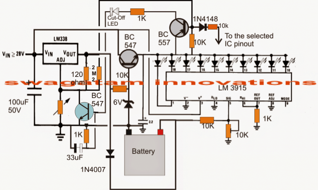
How it Works using LM3915 IC
The circuit functioning may be understood with the following points: The IC LM3915 which is a Dot/Bar voltage display chip forms the main section of the circuit.
The IC has ten linearly incrementing output which sequence one after the other in response to a rising potential fed at its pin#5. Thus the output sequence corresponds to the instantaneous voltage level at the "signal input" pin out of the IC.
The 10K preset associated with the above IC is set as per the battery voltage which needs to be charged. After this the LEds connected at the output linearly indicate the charge level of the battery by illuminating in sequence, and finally when the last LED is lit which happens when the battery gets fully charged, the SCR is triggered shutting off the charging process permanently until the power is reset.
The stage comprising the IC LM338 is a standard voltage regulator IC, the preset associated with IC is set as per the required full charge limit of the connected battery. The transistor BC547 provides a fixed 3V for the connected LEDs for controlling the IC dissipation.
The transistor BC557 remains switched OFF as long as the last LED in the array which may be selected for the full charge indication is not illuminated. As soon as the last "full charge" LED switches ON, the BC557 is also switched ON triggering the SCR.
The SCR instantly grounds ADJ pin of the LM338 completely disabling the IC and the output to the battery. The battery now stops receiving any voltage and thus it is inhibited from getting over charged.
How to Set Up this Circuit
The circuit can be used for charging 1.5V, 3V, 6V, 9V, 12V, 15V, 18V, 21V and 24V batteries, in fact any voltage that may lie between 1 and 24V. Suppose you want to charge a 6V battery, the full charge level for this battery would be 7V.
The setting of the circuit may be done in the following manner:
- Do not connect the battery initially and also keep the SCR gate disconnected from the BC557 network. Apply a relatively higher DC potential at the input of the IC LM338, may be a 9V or a 12V input.
- Adjust the 10K preset under the LM338 such that the battery terminal points receive a 7V output.
- Now adjust the 10K preset under the IC LM3915 such that the last LED just flickers ON at this voltage, meaning at the applied 7V.
- Restore the the SCR gate connection as per the circuit diagram. That's it the circuit is all set now.
- During the charging process each LED will correspond to 7/10 = 0.7 volts, meaning say at 5V the 7th LEd will be illuminated and with a rise of 0.7V the subsequent LED will be lit and the sequence will proceed from 7t to 8th to 9th and then finally to the 10th LEd shutting off the circuit and the charging of the battery.
Alternatively if you you are interested in making the circuit respond with all batteries from 3V to 12V then you may adjust the LM3915 preset such that the last LED barely illuminates at 14.4V.
Now each pinout of the IC corresponding to the relevant LED would sequence at the rate of 14.4/10 = 1.4V, therefore for a 6V battery the full charge LED pinout would be 7/1.4 = 5, meaning the 5th LED illuminated would indicate that the connected 6V battery is now fully charge.
For enabling automatic cut off for the above situation you just have make sure the base of the BC557 is connected to the 5th pinout of the IC LM3915 from left to right.
For a 9V battery it would 9/1.4 = 6.4th LEd, meaning when the 6th LED is fully glowing and the 7th LED is barely flickering, the 7th LEd may be selected and joined with BC557 base for acquiring the required automatic cut off.
Circuit Diagram

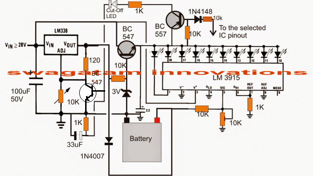
Using Transistor Latch instead of SCR
If the above circuit fails to respond with an SCR, the following circuit using a transistor latch can be employed:
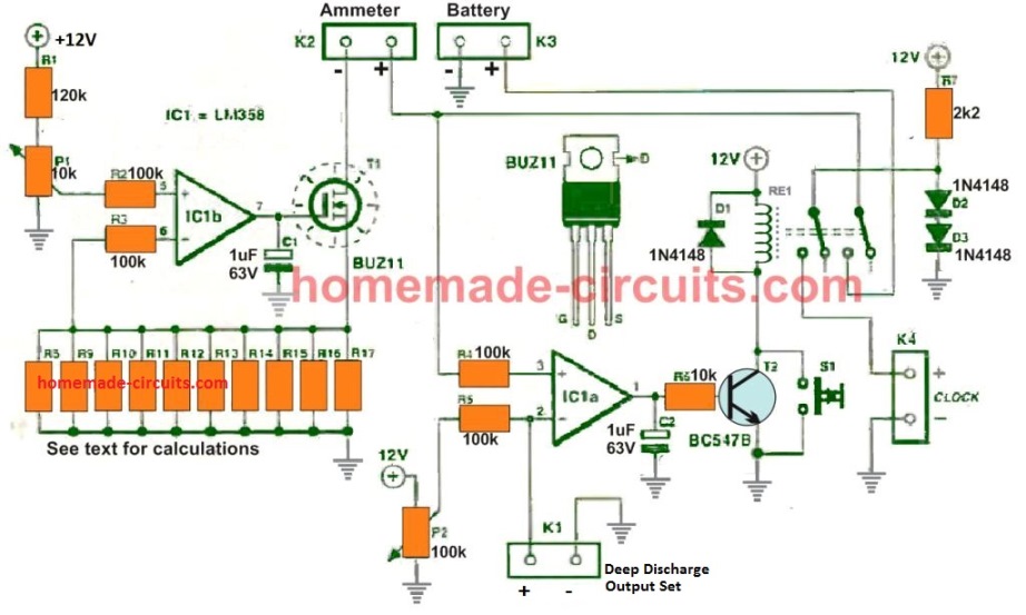
For an Automatic ON/OFF Function
If you want the above multipurpose battery charger circuit to cut off the charger while the battery reaches the full change limit, and then quickly switch ON the charging when the battery starts dropping below the full charge limit, and continue flip flopping at this threshold level, in that case you can try modifying the design in the following manner:
Questions & Answers
Hi Sir,
I agree to your logic but it will take long time , without removing any cap I got a suggestion if we connect an npn transistor base to the base of bc557through a resistor when ever the positive voltage appear fr the ic the transistor will trigger and the ce of tr will get shorted, if we open the cathode connection of scr to ground and connect the c to cathode of scr and the emitter to ground the problem is solved .We can also use this transistor to switch on a small relay and use its contacts in between the scr cathode and ground.
Regards V.Sambath Kumar.
Thank you Sambath,
what you are saying is possible, but it requires extra parts and effort.
Using an unfiltered DC at the input solves this problem in an easier way, and can in fact promote desulphation of the battery and enhance battery life.
Hi Sir,
In the scr version we get a positive voltage through theCE of bc557 to trigger scr to stop the charging , scr once triggred the anode to cathode remains permanently shorted until either cathode or anode is dis connected from the circuit so how do you switch on the charger when the battery voltage come low again.
Regards V.Sambath kumar.
Hi Sambath,
Yes, that’s right, the SCR will get permanently latched and won’t respond when the battery voltage drops to lower level.
To eliminate this issue, you can remove any filter capacitor associated with the input DC, so that the DC after the bridge rectifier comes with a 100 Hz ripple.
Just make sure to connect a 10u/25V across the base/emitter of the BC557 transistor.
Student I want to learn
Using the IC LM338 I needed an indicator at the output that will indicate the battery ???? is fully charged..
Where can I do that on the circuit.?
You can simply connect the following circuit across your battery terminals for showing the full charge:
https://www.homemade-circuits.com/battery-full-charge-indicator-circuit/
OK can I get the full PDF form of this work??
You can easily convert it pdf using any online “URL to pdf converter”
Hello Mr. Swagatan, I need some help with the first lithium-ion battery charger. I’m a hobbyist who enjoys building projects from schematics. I put together the charger on a breadboard but somehow I’m not able to figure out how the potentiometer near the LM338 Var. Regulator is to be wired in. I don’t get the right variable voltages at the battery terminals and I get feed back lighting up the LED’s. After many attempts at retracing my steps I still am unable to make this work. Nothing gets warm and it hasn’t blown any fuses. I need this for charging 9v batteries. Thank you, Ed
Hello Ed,
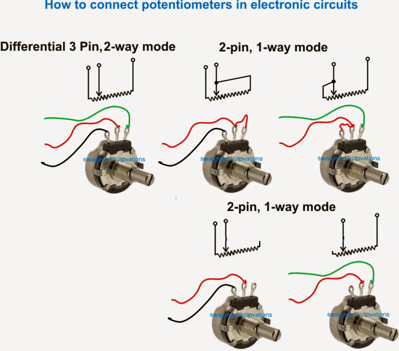
You must use two terminals of the potentiometers for the connections, the center terminal and any one of the output terminals.
An example image of the pot connections can be seen below:
Please see the “2-pin 1 way mode”, you can use any one of those methods.
Make sure not to connect a battery while adjusting the LM338 output voltage. Adjust the voltage by connecting a meter across the points where the battery is supposed to be connected.
Connect the battery only once the pot adjustment is completed and the voltage is correctly set.
Also, make sure that the collector link of the BC557 transistor remains disconnected while the voltage adjustments is being done. Restore the connections once the voltage adjustment has been completed.
Nice circuit diagram
24v battry chager transformer calqultion data
Hi, Greetings dear Swagatan, how are you? The circuit is very interesting, but the LM3915 is difficult for me to find. Could you suggest a circuit with similar functions: to charge 3V, 4,5V, 6V, 9V, 12V batteries, but using IC LM 7805 or any of the LM78xx series? A Yotta of thanks, Joakin
Hi Joakin, There’s no replacement for LM3915. Instead you can build a variable power supply unit using transistors or an IC LM338 which can be adjusted to suit any battery voltage.
https://www.homemade-circuits.com/how-to-make-current-controlled-12-volt/
Hi, thank so much for your answer,
Dear Swagatan the LM3915, can not be replaced by LM3914?.
In my letter I do not ask to replace the ic lm3915, but to make a circuit that does the same function, but uses LM78xx. Tell me a way to send you the circuit, cause this way i dont see how to do that. Thank you. Joakín
Hello Joakin, yes LM3915 and LM3914 are two versions of the same IC and are interchangeable.
It can replicated by using 10 separate op amps, as found inside the LM3915 IC:
You can upload your circuit to your Google drive and send me the link here, I will check out the circuit.
make sure to remove the https from the link.
Good morning Swagatam, hope you are well,
In the charging circuit with automatic ON/Off function there are 3 capacitors, 1 = 100mF, 50V, 1 = 33mF and 1 just above the battery of 2,2mF. (dwg which I downloaded not very clear) What the voltages be on the last 2 caps?
Another issue is all of electronic suppliers locally tells me – No stock of the LM3915 IC, what now? What other IC can I use?
Best regards,
Marius
Good Morning Marius,
the rule of thumb is that the capacitor voltage must be 1.5 times or 2 times the supply voltage. So if the supply voltage is 12V then the capacitor minimum voltage can be 20 V or 25V, or any higher value.
LM3915 is a pretty standard IC, so it is strange if it’s not available in your area, nevertheless you can always order them through any online electronic stores or through Amazon and eBay.
Unfortunately there’s no replacement for this IC, unless external op amps are configured to implement the same job….
Thank you very much for your valuable reply, will have to go your recommended route
God bless
I am glad to help!
Hello Swagatam,
Pls can this your circuit charge lithium batteries or they are for lead acid batteries?
Thanks for your response.
Regards
Ebai
Hello Richard, you can use the concept for Li-ion battery also, just make sure to use an input current that’s 50% of the mAH rating of the battery.
Dear Sir,
I want to charge 4 mobile phones using a 12v motorcycle battery.What should I do?
What is the circuit diagram?
Please help me.
Thank You
Hello Praveen, you can try the 5) LM338 based design from the following article:
https://www.homemade-circuits.com/how-to-make-simple-dc-to-dc-cell-phone/
Since motorcycle battery gives a DC current, How should I changed the above circuit??
You can eliminate the transformer and the bridge, and modify the circuit in the following manner:
Dear mr Swagatam,
Possible to make automatic battery charger 12v 24v 200ah diagram using pulse/ferrit (EE35/PQ3230) transformer for saving cost to made it
GBU
Thanks and regards
St
Dear Salim, I do not have a 20 amp SMPS design, and it would be a pretty complex design for sure, better to get one readymade
Dear Mr. Swagatam, No need rewinding coil SMPS, just make from SMPS ready to use (EE35/PQ3230), most of them many and easy to find in the online marketplace ☺️
OK, thanks for the feedback!
DEAR MR SWAGATAN DO YOU HAVE A SIMPLE TRANSISTOR CIRCUIT 12V 50A- 80AMP CHARGER THAT HAS AN AUTO CUT OFF WHEN BATTERY IS FULL
Hello Jemithias, You can refer to the following articles. You may find them useful:
https://www.homemade-circuits.com/simplest-smf-automotive-battery-charger/
https://www.homemade-circuits.com/self-regulating-lead-acid-battery/
Hi Mr. Swagatam, I found this circuit of great interest. My need for charging is: During long driving hours, during holiday periods, in my vehicle my wheelchair can be fully charged. In my vehicle I have provided 12 volt 30 amp cable (8mm2), to place the wheelchair is located. The wheelchair has AGM 12 volt 70A X2, series connected to 24 volts.
I have found a Step up converter, max 15A in / 440 watts, where I have to convert 12 volt voltage in the vehicle up to approximately 27 volts which is applied over the LM338K input (TO3 ver.) I would use technical form 3, For an automatic ON / OFF function
1. LM338 can deliver 5A max, how can I connect 2pcs LM338 in parallel that can provide up to 10A charging current and drastically reduce the charging time? I have read that the adj. line LM338 connected in parallel must be checked to be exactly the same / identical, for example with the use of an op.amp ic which controls the voltage on the output line. I found such a connection, but it may indicate it would be difficult to fit into diagram # 3. https://1drv.ms/u/s!AizwNFNuGCzdtIxNDWUJJql4ORm_nw?e=nhn7wJ Do you have another better idea/solution to gain up charge current?
You have a nice calculation technique for the LM3915, as follows: “Alternatively, if you are interested in getting the circuit to respond with all batteries from 3V to 12V, you can adjust the LM3915 preset so that the last LED light barely lights up at 14.4 V.
Now each pinout of IC corresponding to the current LED sequence at a speed of 14.4 / 10 = 1.4V, therefore for a 6V battery the LED pinout with full charge would be 7 / 1.4 = 5, which means that the fifth LED will indicate that the connected 6V battery is now fully charged. ”
But how does this work out for 2pcs 12 volt AGM batteries in series (24 volts)? Here I should connect BASE to BC557 / PNP to LED furthest to the RIGHT, when output voltage is regulated under LM338 to around 27.5 volts?
Thank you for your incredible and extremely good electronics guide pages.
Hi again, Swagatam , and thank for you feeback, a support joy you show me, I will share with you.
I now made a new diagram for this 3v, 4.5v, 6v, 9v, 12v, 24v, automatic charger. Since I now wanted a doubling of the charging current, 5 amps up to 10 A, some change of the schematic diagram was necessary. I now removed the cut of transistor in the adjust inputs of my two LM338, and replaced this control performed by an Op amp. UA741. The emitter output in the attached diagram (Q4) now controls the regulator for the LM338 voltage level. Two 0.3ohm / 10W resistors are mounted in the outputs of the LM338. Note LED1, marked with a red circle, cut off voltage at measured charging voltage, 27.5 volts in my project, is this connected to the correct side, inverted / not inverted side of Op amp.?
Thank you so much for the response, a support that makes it a pleasure to spend my free time with electronic building projects!
Se my new diagram (with a fan speed controller (LM358) to a fan mounted at LM338 cool radiator ribs)):
https://drive.google.com/file/d/1BcWFbQ4H9nvMQs__i-Ixc0oCYdoVJD96/view?usp=sharing
Thank you Anderson, I appreciate your interest and efforts, however it seems the link you have sent was not set to the shared mode, and therefore it isn’t opening at my end. After referring to the diagram I should be able to provide you with my opinion.
Thank you Mr.T.Andersson, I appreciate your interest and curiosity regarding the concepts explained above.
To get 10 amp output you can connect two LM338 pins in parallel with a common regulator circuit, and also make sure to mount the two ICs over a common heatsink so that they can share the dissipation uniformly.
Yes, for a 12 V battery the 5th LED will correspond to 7V and so forth.
For a 24V battery the 5th LED will correspond to 14 V, but the indication range will keep getting squeezed more and more as the battery source voltage increases. Yes you will have to depend on the furthest LED (10th) for the full charge cut off(28V), and for the BC557 base integration.
Mr. Swagatam and I’ve seen those tutorials from different sources and battery chargers and I’m very interested in those topics because I work with electronics, maybe not very advanced but I understand a little of the basics but I don’t know if my question is related to what in this This page is commented but I have always wanted to make a my good battery charger but also annelo to make a My little welding machine I think that maybe that is another issue but I wish if you were so kind to guide me in this regard, notice that I have 2 toroidal transformers, it is 20 centimeters diameter by 7 high I do not know if you could guide me if I can join the 2 primaries and remove the secondary of the two and make a single one for the output and if possible, what gauge of wire would be used or any guidance that will give me I am grateful in advance for yourattention I hope you can read my writing I will be waiting for any suggestion a thousand thanks in advance
Hello Edgar, designing or amending transformers require critical calculations, and cannot be judged through assumptions. So I am sorry it won’t be possible for me to suggest regarding the transformer winding that you have asked.
Hi Swagtam, i want to charge my 3 lion battery connected in series with a 12 volt 2 amp charger. I dont want to display the full led indicator for battery capacity. Only i want to automatic charge and cutoff when fully charge without a relay. Pls give me solution. Also i want to charge a 3.7 volt single cell lion battery also. Pls give solution.
Hi chandrashekhar, you can use the second last concept from this article:
https://www.homemade-circuits.com/usb-automatic-li-ion-battery-charger/
use 12V as the input instead of the shown 5V, and set the preset for the desired level cut off
Hello Mr. Swagatam.
I have been following you for a long time. I need your help. I have a 14.8v, 2.1Ah, 31.1Wh lithium-Ion battery. To charge this battery, I have to design a circuit with automatic charge cut and charge status indicator(with led). Which is the most suitable circuit for me in this regard. Can you help me? Thank you for your interest. See you.
Respects.
Hello, Mr. Sw.
Thank you very much for your interest. I do not want to use the relay
in the circuit. Can you suggest another circuit that I can use instead?
Noble, Then you can try the other circuit which is without relay in the same article…second last one may be
Thanks Noble, you can try the last circuit from this article:
https://www.homemade-circuits.com/usb-automatic-li-ion-battery-charger/
Replace the relay with a 12V relay.
Replace the transistor base resistor with 10K
Use a 16V input with 1 amp current.
SET the preset to get a precise 14.8V cut.
Hi Swagatam,
i like your posts. i am having littlebit knowledge of electronics.
i have 24V 2A smps power supply.
1) can i use this power supply as a battery charger to charge 12volt 100ah battery
2) what circuit is required additinally.
t&R
Prashant
Thanks Prashant, you can use a buck conveter to convert 24V 2 amp to 14V/ 3.5 amps, but this current can be too low to charge a 100 Ah battery, as it will need minimum 8 to 10 amps for optimal charging within 12 hours
hi,
thanks for your reply,
it is possible with this ps obtain higher current? or required new transformer with rating 24-0-24v 10amp
Transformer rating will need to be increased. The ideal transformer would be a 12V 10 amps which will become 16V 10 amp after rectification