In this article we look into a simple 220V mains PWM controlled fan or light regulator circuit which does not require a microcontroller or costly triac drivers for the intended operations.
Capacitive Phase Chopping
All Ordinary types fan regulator and dimmers which rely on capacitive phase chopping technology have one drawback in common, these generate a lot of RF noise and require bulky inductors for controlling them partially.
Furthermore, the switching or the phase chopping being done using ordinary capacitor diac technology lack accuracy and sharpness.
The proposed mains transformerless PWM controlled fan regulator circuit designed by me is free from all such possible issues normally accompanied with traditional fan or light dimmers since it uses an advanced CMOS IC based circuit and an accurate zero crossing detector stage.
No MCUs Used
The best thing about this circuit is that it does not require microcontrollers and programming, and also a triac driver has been eliminated making the circuit extremely easy to build even for the new hobbyists.
I have explained the configuration in detail, which is rather too straightforward:
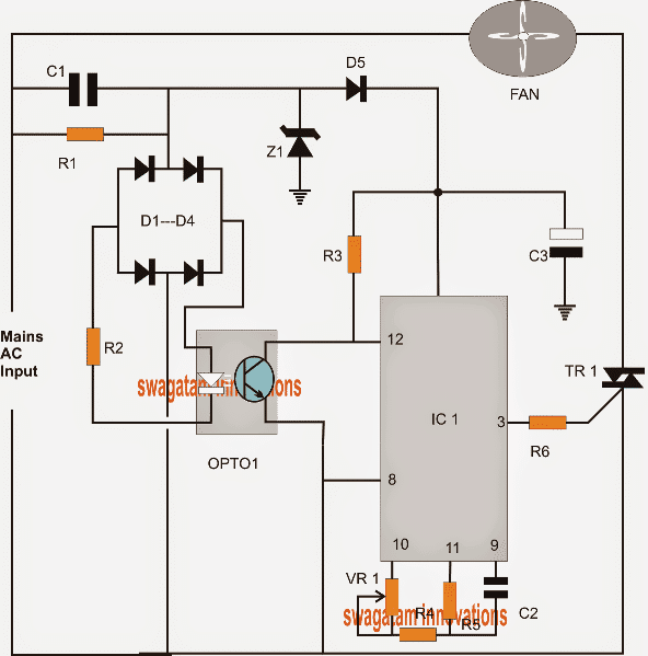
Referring to the circuit, IC1 which is a 4060 timer chip is configured to produce a delayed positive pulse for the triac each time the phase crosses the zero line of its phase angle.
The entire circuit is powered from an ordinary capacitive power supply using C1, D5, Z1 and C3.
IC1 is configured in its standard form for generating a delayed switch ON or a high every time its pin12 goes through a reset action.
Zero Crossing Switching for the Triac
The dimming action or the phase control action is achieved by making the triac to conduct after a predetermined delay each time a zero crossing is detected.
If this delay is short, it means the triac gets an opportunity to conduct for a greater amount of time for the phase angles, causing the connected fan to spin faster or the light to shine to brighter.
As this delay is increased, the triac is forced to conduct for proportionately shorter durations across the phase angles producing a proportionate amount of reduction over the speed or the brightness of the connected fan or the light respectively.
The zero crossing operation is simply enforced by using an ordinary opto coupler, as can be witnessed in the given diagram.
The bridge D1---D4 transforms the alternating phase angle into equivalent 100 Hz positive pulses.
The LEd and the transistor inside the opto coupler responds to these positive 100Hz pulses and stays switched ON only for so long as the pulses are 0.8V above the zero mark and switches OFF instantly as the pulses reach the zero crossing point.
While the opto transistor is in the conducting phase, the IC pin12 is held at ground level allowing a delay or a predetermined negativestarting pulse for the triac gate.
However at the zero crossing levels the opto switches OFF, resetting the pin12 of the IC such that the IC pin3 restarts a fresh or a new delay for the triac to respond for that particular phase angle.
PWM Phase Control
The length or the pulse width of this delay pulse can be varied by suitably adjusting VR1 which also becomes the speed control knob for the discussed PWM controlled fan regulator circuit.
VR1 and C2 must be selected such that the maximum delay produced by these should not exceed the 1/100 = 0.01 second timing in order to ensure a linearly incrementing 0 to full calibration over the given control knob.
The above could be implemented by some trial error or by using the standard formula for IC 4060.
For the above you may also experiment the other outputs of the IC.
Circuit Diagram
Construction and Connection
Power Supply Section
C1 (Capacitor):
Connect one terminal of the high-voltage capacitor (e.g., 0.33uF, 400V) to one of the AC mains input wires.
Connect the other terminal to one of the input terminals of the bridge rectifier (D1–D4).
D1–D4 (Bridge Rectifier):
Arrange the diodes to form a bridge rectifier.
Connect one AC terminal of the bridge rectifier to C1, and the other AC terminal to the other AC mains input wire.
The positive output of the bridge rectifier goes to the zener diode (Z1) and the circuit's DC supply.
The negative output serves as the ground, for the circuit.
Z1 (Zener Diode):
Connect the cathode of the zener diode (marked end), to the positive output of the bridge rectifier.
Connect the anode to ground.
This zener regulates the DC voltage for the control circuit, (typically 12V).
R1 and R2 (Resistors):
R1 connects in series with C1 to limit the current from the AC mains.
R2 connects between the positive DC supply, and the optocouplers input LED (inside OPTO1) to limit the current through the LED.
Oscillator Setup with the 4060 IC
The 4060 IC is used to generate a timing signal. Follow these steps to configure the oscillator:
Pin Connections:
Pin 16 (Vcc): Connect to the positive DC supply (regulated by Z1).
Pin 8 (GND): Connect to the ground.
Pin 12 (Oscillator Output): This pin outputs the oscillating frequency and is used as the input to the TRIAC/MOSFET gate.
Resistors (R3 and R6) and Capacitor (C2):
Connect R3 between Pin 10 and Pin 11 (oscillator timing pins).
Connect R6 between Pin 11 and Pin 9 (oscillator input pin).
Connect C2 between Pin 9 and ground.
These components set the frequency of the oscillator.
Formula for frequency (f):
f = 1 / (2.2 * R3 * C2)R3 = Timing resistor between Pins 10 and 11.
C2 = Timing capacitor between Pin 9 and ground.
Adjust R6 (or replace it with a variable resistor/VR1) to fine-tune the frequency.
Reset Pin (Pin 12):
Leave this unconnected if not needed, or connect to ground via a small resistor to avoid floating.
Oscillator Output (Pin 3 or another Q Output):
Choose an appropriate Q output pin (e.g., Pin 3 or others like Q4, Q5) to deliver the timing signal to the gate/base of the TRIAC/MOSFET (TR1).
The selected Q pin depends on the desired frequency division factor.
Output Switching Section
TR1 (Switching Device - TRIAC/MOSFET):
Connect the gate/base of TR1 to the oscillator output pin (e.g., Pin 3 of IC 4060) through R3.
Connect one terminal (MT1/source) to the AC mains neutral and the other terminal (MT2/drain) to one end of the fan.
D5 (Freewheeling Diode):
Place D5 across the fan terminals as a protection mechanism.
Fan Load
Connect the fan in series with the TRIAC/MOSFET.
- One terminal of the fan connects to the AC live wire.
- The other terminal connects to MT2 (or drain) of TR1.
Ensure that the fans current and voltage ratings match the circuit's capacity.
Adjusting the Fan Speed
Frequency Tuning:
The fan speed is indirectly proportional to the frequency of the oscillator.
Adjust R6 or replace it with a potentiometer (VR1) to control the oscillator frequency, which alters the effective power delivered to the fan.
A lower frequency allows the TRIAC/MOSFET to remain "on" for a longer time, increasing the fan speed.
Zener Diode Protection:
Use a zener diode across the fan terminals to clamp voltage spikes.
Formulas and Calculations
Oscillator Frequency:
f = 1 / (2.2 * R3 * C2)R3 and C2 define the base frequency.
Effective Power Delivered to the Fan:
P = V * I * Duty CycleAdjusting the oscillator frequency indirectly controls the duty cycle and, consequently, the power.
Capacitor Selection for Timing (C2):
C2 = 1 / (2.2 * f * R3)Assembly Notes
4060 IC Socket:
Use an IC socket for mounting the IC, because as this makes it easier to replace in case of failure.
PCB Layout:
Place the timing components (R3, R6, C2) close to the 4060 IC to reduce the noise.
Testing:
Before connecting the fan use an oscilloscope to verify the frequency at the oscillator output pin.
Adjust R6/VR1 and, observe the changes in frequency.
Parts List
R1, R5 = 1M
R2, R3, R4 R6 = 10K
VR1, C2 = SEE TEXT
OPTO = 4N35 OR ANY STANDARD
C1 = 0.22uF/400v
C3 = 100uF/25V
D1---D5 = 1N4007
Z1 = 12V
IC1 = 4060
TRIAC = BT136
Waveform Simulation
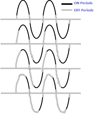
The delay waveform image below shows how the phase for the fan may be delayed at every zero crossing, for the various settings of VR1 and C2.
Smart PWM Fan Regulator Using IC 555
Almost all light/fan regulator circuits make use of a silicon-controlled rectifier (triac or SCR).
These devices are switched with a predetermined phase angle which subsequently stays in the conduction mode until the following zero crossing of the mains AC cycle.
This process looks easy, however simultaneously it presents difficulties while controlling smaller loads or which are inductive in nature causing hysteresis and flickering.
The reason of these issues depend on the truth that due to smaller load wattage the current delivered to the devices is inadequate to sustain their conduction.
Therefore a region of the control characteristic is not thoroughly implemented. The outcome further deteriorates for the loads that are inductive.
How the Circuit Works
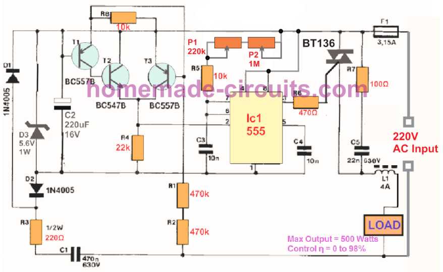
The proposed AC 220V PWM regulator circuit using IC 555 gives you a simple solution by supplying the triac with a constant gate current, to ensure that loads as nominal as 1 watt is also controlled smoothly.
To have the circuit as compact and straightforward as it can be, we utilize the popular timer IC 555.
The output of the IC 555, which can be typically triggered high, is activated low through a negative potential input.
This negative supply is made available from the stage comprising C1-R3, rectifier D1 -D2, along with stabilizer section D3-C2. BJTs T1 to T3 deliver a initializing pulse on the trigger input pin#2 of the 555 for each of the zero crossings of the mains AC input.
During a PWM period, as decided by the adjustment of P1 and P2, the output of the IC 555 is usually high, and we, therefore, have practically zero voltage difference across pins 3 and pin 8, i.e. the triac remains switched off.
As soon as the set interval is elapsed, pin 3 becomes low and the triac is activated.
For the rest of the half AC cycle, a gate current keeps running, which allows the the triac to continue to conduct.
The lowest point where, let's say, a light bulb need not just illuminate, is determined by carefully adjusting the pot P1. Filter R7 C5 L1 supplies the necessary decoupling for the triac.
As a final point, remember that the absolute maximum power that could be governed by this IC 555 based smart regulator switch should not exceed 600 watts.



Questions & Answers
Hi Swagatam,
i want to ask on how can i reduce a line AC voltage from 230V to 200V? is ithere a circuit for this? i have a contactor witch the coil is 200V and my grid is 230V. i hope you can help me for this to use of my contactor.
Thanks in advance,
Oliver
Hi Oliver,
you will need a 25-0-25V /5amp/230V step down transformer which you can wire up to get a reduced voltage upto 205 or 200V as per your requirement.
the wiring instructions can be found in the following article:
https://www.homemade-circuits.com/2011/12/how-to-build-2-stage-mains-power.html
thank you swagatam… your an angel
you are welcome dear!!
Hi..swagatam,
please help me to make a circuit…
i want to make a micro-controller less,MOC3041 opto base heater dimmer…
Hi Arpan, you can find plenty of such circuits on the web, please type the keywords and you will come across many.
Sir,
I google about this circuits in web…but it result aurdino or any microcontroller base dimmer..i can't find any MOC3041 opto and op-amp ic base dimmer..
Arpan, why don't you try the above circuit, I have eliminated the use of MOC3041 and made the design even simpler.
…or you can try the following circuit:
2.bp.blogspot.com/-sRFuO1CGSzI/U4wtybAo_YI/AAAAAAAAHFA/nE9Uo6Qhdho/s1600/triac+controlled+PWM+inverter+circuit.png
MOC3021 has a built-in zero crossing detector so you won't need to worry about that…the pWM input could any square wave signal having pulse timing of 0.01 seconds
the inverter output may be replaced with 220v AC mains input at extreme right of the circuit
Thank you swagatam sir..thank you..
Hi Swagatam,
what is the best value of Rt and Ct?
Thanks
Hi Oliver, if you are referring to the above 4060 circuit, it can be identified best through some trial and error….ideally the range should be within 1/100 = 0.01 second….. meaning within 0 to 0.01 second
do i have to add the R4 to VR1 for the computation?
R4=10k, VR1=5k = Rt=15k
Ct=0.01
f = 1/(2.3*15*0.01) = 2.89
t = 1/2.89*16 = 5.5sec
16 is pin7 or Q4
correct me if i'm wrong…
Thanks
VR1 is a pot or a variable resistor, R4 is for making sure that even at minimum pot value the IC does not stall.
It would be difficult to identify the exact values of the pot and the capacitor…
pin 16 is the supply pin of the IC which joins with D5, C3, R3, mistakenly not shown in the diagram.
Hi Swagatam,
I have built your PWM Controlled Fan Dimmer Switch Circuit (as shown above) – running on 60Hz 120 volts. I am using a 100k pot for VR1 and a C2 capacitor of .1uF which does not work.
How can I calculate the value of C2?
Or can you give me a guess of what might be close?
Thanks
Randy
Hi Randy, calculating C2 with respect to VR1 can be quite difficult unless you do it through an oscilloscope or with some relentless experimentation. I'll explain how it is supposed to work
the optocoupler will switch ON as soon as the mains phase has crossed the zero crossing point, and will remain switched ON until the phase has reached back to the next zero crossing……since this may happen 60 times per second (in your country), and after rectification 120 times, the period for which the opto remains ON can be calculated as 1sec/100 = 0.01 second
the 0.01 second is the time range for which the IC pin#12 stays grounded and allows the IC to initiate the counting of it timimng cycle.
Therefore we have this 0.01 sec range in which the RC timing components must be adjusted such that the triac gate triggers after a certain delay inside this 0.01 second slot.
For example suppose the VR/C2 are adjusted such that the IC triggers the gate after a period of 0.005 second would imply that the triac is allowed to conduct for the next 0.005 second within the stipulated 0.01 second…that's 50% conduction and would allow the fan to rotate at 50% speed….and so on.
therefore in short the VR/C2 have a time slot of 0.01 second range under which these have to decide after how much delay the triac could be switched ON until the next zero crossing, which would go repeating for every phase causing that much amount of speed on the fan.
I'll possibly try to update another circuit using two 555 IC and by implementing a "time proportional" control theory…that will hopefully be easier to understand and execute than the above theory.
correction:
sorry…the period for which the opto remains ON can be calculated as 1sec/120 = 0.0083 second
Dear Sir Swagatam
The ground plane PWM regulator circuit is the negative you get the rectifier bridge D1-D4, I mean where is the negative of Z1, C3 and IC1.
Thank you very much for your reply
Best regards
Dear AIFa,
the bridge is only for the opto and for implementing the zero crossing detection….the actual ground of the circuit the line which connects with pin8 of the iC 4060
Thank you very much dear Swagatam.
Dear sir can i use MOC3021 with BTA41 600V for light dimmer or motor speed controller
Dear Rakesh, yes you can use them together
Thank you sir
Dear sir
what is voltage value of 0.05uf and 0.01uf in your circuit diagram
2.bp.blogspot.com/-sRFuO1CGSzI/U4wtybAo_YI/AAAAAAAAHFA/nE9Uo6Qhdho/s1600/triac+controlled+PWM+inverter+circuit.png
Dear Rakesh, It's 400V for both
Ok and thank you sir
Dear sir MOC3021 it's not proper work with BTA41 for light dimmer circuit
this is on and than off, not a dimming condition
so please sir solve this problem
you must apply varying pwm at the input side of MOC3021, only then it will respond with the dimming effect
Dear sir please एक last question है
आप के दिए हुवे circuit में (जिसका address नीचे दिया हुवा है) 470R के दो resistance लगे हुवे है
अगर मै BTA41 की जगह पे BT139 use करता हूँ तो उन 2 जगहों पे कितने value के resistance की जरुरत पड़े ही जहा 470R के 2 resistance लगे हुवे है
please sir
2.bp.blogspot.com/-sRFuO1CGSzI/U4wtybAo_YI/AAAAAAAAHFA/nE9Uo6Qhdho/s1600/triac+controlled+PWM+inverter+circuit.png
Dear Rakesh, no need to change the resistor values, you can use the same values for BT139 also.
Ok sir Thank you
Hello Swagatam, Appreciate your help and documenting these design for new comers like me.
I am trying to find a fan speed controller without a POT/VR1 and instead use Arduino software to control the speed of the fan. I did see you other image-
2.bp.blogspot.com/-sRFuO1CGSzI/U4wtybAo_YI/AAAAAAAAHFA/nE9Uo6Qhdho/s1600/triac+controlled+PWM+inverter+circuit.png
Do you think that circuit would help in controlling the inductive fan speed just with PWM from Arduino?
Appreciate your guidance.
Regards,
Samrat
Thank you Samrat,
No, the picture that you have shown was designed on a mistaken assumption, triacs can never be controlled through PWM, except the method explained in the above article or as implemented in triac dimmer circuits.
sir i want to make Ac fan speed controlling .i want seketch of arduino for controlle the speed of through serial monitor of arduino IDE
Please, how can I reduce the power wattage of my plasma TV 440w. Any circuit.
Please, how can I reduce the power Consumption for wattage of my plasma TV 440w. Any circuit.
sorry, no ideas
Hi
Can we control the speed according to temperature using NTC or PTC in this circuit?
Hi,
yes that’s possible by using the following concepts:
https://www.homemade-circuits.com/automatic-temperature-regulator-circuit/
https://www.homemade-circuits.com/making-simplest-room-thermometer/
https://www.homemade-circuits.com/?s=thermostat
Hello Mr. Swagatam
I’ve looked at all this information with admiration. What I want to ask is, can we use NTC instead of VR1 in this circuit?
In other words; Can the AC FAN dimmer circuit be designed with THERMISTOR control to control the speed of the AC asynchronous motor?
Best regards
Hello Tekin, is your motor a 3 phase motor? A single phase can be perhaps controlled with an upgraded light dimmer circuit, and with thermistor
Dear Swagatam
Ac Fan motor 1 Phase Asynchronous motor. I can do speed control with Trimpot. However, I want to control the speed of the fan motor with a thermistor to detect the ambient temperature. For example, when the ambient temperature is 40 degrees Celsius, the fan will run at full speed. At about 20 degrees the fan motor will work as 50%.
I need your support to do this
Thank you.
Dear Tekin,
I think you should try the following concept, it has more chances of fulfilling the requirement, if optimized correctly:
https://www.homemade-circuits.com/automatic-temperatureclimate-controlled/
Sir, isnt it dangerous to connect the TRIAC Gate pin directly to IC 4060 as Mains supply is flowing
Haider, the shown wiring is not dangerous for the IC or the triac, but it is dangerous for a human to touch the circuit in switched ON condition
1)Respected Sir, is there a test simulation(proteus simulation ) or a video showing the working of the circuit ,tested on live bulb or fan.
2) is there a way i can alter this circuit a little bit , so i can interface it with a micro-controller and add a digital potentiometre ,replacement with a regular knob potentiometre , in result i can control the speed of the fan or brightness of the lamp just through control from microcontroller
Thank u
Hello Haider, I do not have any proteus simulation results for this circuit, it was developed purely through my knowledge and my brain simulation.
Sorry No, a microcontroller pot cannot be used in the indicated VR1 position.
Sir, does any one or have u tested on a fan or a bulb , do u have any video which shows as a working circuit , so that it would satisfy as working circuit and i would have no doubts
Thank u
hey Swagatam, i am just confused …in the above wave form shown…in one complete sine wave there are 2 zero crossing ,so…why the triggering effect comes only at (0,360,…n360) and not at (180 ,n180…) since the delay trigger should be generated after every 0 crossing (0,180,360…)
Hey Brainstormer, the circuit will respond to every zero crossing, since the bridge rectifier would be feeding every AC cycle to the opto coupler. Therefore at every zero crossing the IC would be resetting and starting the delay afresh, causing the triac to switch OFF and switch ON back only for the specified amount of delay, as set by the VR1 pot.