In a triac phase control circuit, the triac is triggered ON only for specific portions of the AC half cycles, causing the load to operate only for that period of the AC waveform. This results in a controlled supply of power to the load.
Triacs are popularly used as a solid-state replacement of relay for switching high power AC loads. However, there's another very useful feature of triacs which allows them to be used as power controllers, for controlling a given load at a desired specific power levels.
This is basically implemented through a couple of methods: Phase control and zero voltage switching.
Phase control application is normally suitable for loads like light dimmers, electric motors, voltage and current regulation techniques.
Zero voltage switching is more appropriate for restive loads such as incandescent lamps, heaters, soldering irons, geysers, etc. Although these can be also controlled through phase control method.
How Triac Phase Control Works
A Triac could be triggered into activation across any portion of an applied AC half-cycle, and it will continue to be in the conducting mode just until the AC half cycle has reached the zero crossing line.
That means, when a triac is triggered at the start of each AC half-cycle, the Triac would essentially turn ON just like an ON/OFF switch, toggled on.
However, suppose if this triggering signal is used somewhere at midway of the AC cycle waveform, the Triac would be allowed to conduct simply for the leftover period of that half-cycle.
And because the Triac activates for only half the period, it proportionately cuts down the power being supplied to the load, by approximately 50% (Fig. 1).
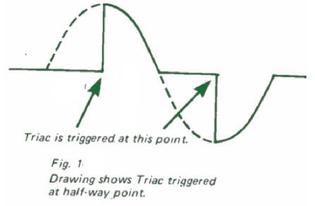
Thus, the amount of power to the load could be controlled at any desired level, merely by varying the triac triggering point on the AC phase waveform. This is how phase control works using a triac.
Light Dimmer Application
A standard light dimmer circuit is presented in Fig. 2 below. In the course of each AC half-cycle the 0.1µf capacitor gets charged (through the resistance of the control potentiometer) until a voltage level of 30-32 is reached across its pinouts.
Around this level the trigger diode (diac) is forced to fire causing the voltage to pass the trigger the gate of the triac.
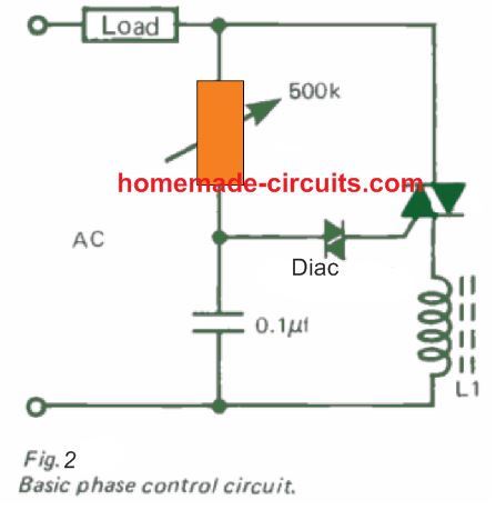
A neon lamp may also be employed in place of a diac for the same response. The time utilized by the 0.1µf capacitor to charge upto the firing threshold of the diac is dependent upon the resistance setting of the control potentiometer.
Now suppose if the potentiometer is adjusted to a zero resistance, will cause the capacitor to charge instantly to the diac's firing level, which will in turn cause the to go into conduction for pretty much the entire AC half-cycle.
On the other hand, when the potentiometer is adjusted at it maximum resistance value might cause the capacitor to charge to the firing level only until half-cycle has almost reached its finishing point. This will allow the
Triac to conduct only for a very short time while the AC waveform travels across its end of the half cycle.
Although the dimmer circuit demonstrated above really is easy and low-cost to construct includes one significant limitation - it doesn't allow a smooth control of power on the load from zero to maximum.
As we rotate the potentiometer, we may find the load current rising pretty abruptly from zero to some higher levels from where this could only then be operated smoothly in the higher or the lower levels.
In the event the AC supply is briefly cut off and the lamp illumination goes below this 'jump' (hysteresis) level, the lamp remains switched off even after the power is finally restored.
How to Reduce Hysteresis
This hysteresis effect could be substantially lowered by implementing the design as shown in the circuit in Fig 3 below.
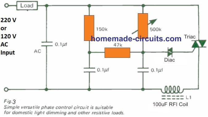
This circuit works great as a household light dimmer. All parts could be fitted at the rear of a wall switch board and in case the load happens to be below 200 watts, the Triac could work without depending on a heatsink.
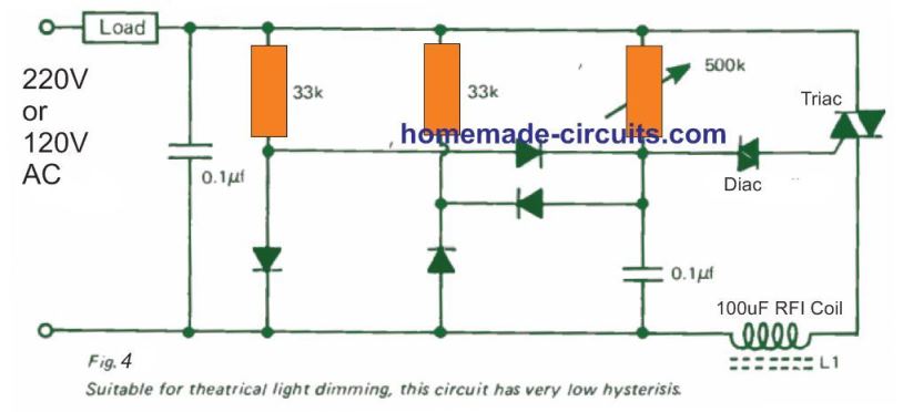
Practically 100% absence of hysteresis is necessary for light dimmers used in orchestral performances and theaters, to enable consistent illumination control of the lamps. This feature may be accomplished by working with the circuit revealed in Fig. 4 below.
Selecting the Triac Power
Incandescent bulbs pull incredibly large current during the period the filament reaches its operating temperatures. This switch ON surge current might surpass the rated current of the triac by around 10 to 12 times.
Luckily household light bulbs are able to reach their operating temperature in just a couple AC cycles, and this brief period of high current is easily absorbed by the Triac without any issues.
However, the situation might not be the same for theatrical lighting scenarios, in which the bigger wattage bulbs require much longer time to attain their working temperature. For such type of applications the Triac has to be rated at a minimum of 5 times the typical maximum load.
Voltage Fluctuation in Triac Phase Control Circuits
Each of the triac phase control circuits displayed thus far are all voltage dependent - meaning, their output voltage varies in response to the changes in the input supply voltage. This dependence on voltage could be eliminated employing a a zener diode which is able to stabilize and keep the voltage across the timing capacitor constant (Fig. 4).
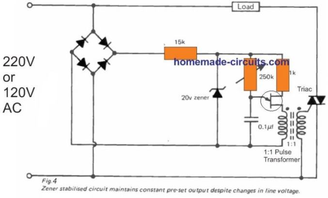
This set up helps to sustain virtually a constant output regardless of any significant variations in mains AC input voltage. It is regularly found in photographic and other applications where a highly stable and fixed level of light becomes essential.
Fluorescent Lamp Control
Referring to all the phase control circuits explained so far, incandescent filament lamps could be manipulated without any additional alterations to the existing home lighting system.
Dimming Fluorescent lamps may be also possible through this kind of triac phase control. When the outer temperature of halogen lamp falls below 2500 degrees C, the regenerating halogen cycle becomes non-operational.
This may cause the filament Tungsten to be deposited over the wall .of the lamp, decreasing the filament life and also restricting the transmission of illumination through the glass. An adjustment which is often employed along with some of the circuits reviewed above is demonstrated in Fig. 5
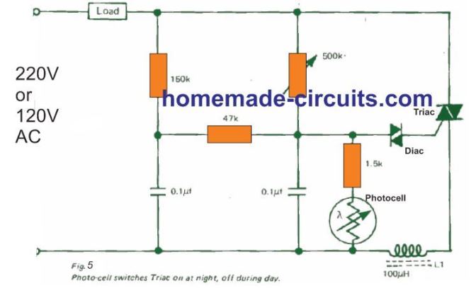
This set up turns ON the lamps as darkness sets in, and turns them off again at dawn. It is necessary for the photo cell to see the ambient light but be shielded from the lamp which is being controlled.
Motor Speed Control
Triac phase -control also enables you to adjust the speed of electric motors. The general kind of series-wound motor could be governed through circuits much like those applied for light dimming.
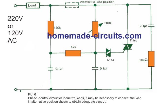
However, to guarantee reliable commutation, a capacitor and series resistance needs to be hooked up in parallel across the Triac (Fig. 6).
Through this set up the motor speed can vary in response to changes in load and the supply voltage,
However, for applications that are not critical (for example fan speed control), in which the load is fixed at any given speed, the circuit won't require any changes.
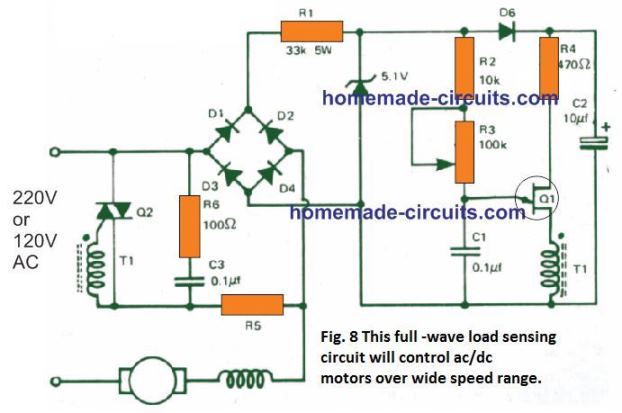
Motor speed which usually, when pre-programmed, is kept constant even with changes in the load conditions appears to be a helpful characteristic for power tools, laboratory stirrers, watchmakers' lathes potters' wheels, etc. To achieve this 'load sensing' feature, an SCR is usually included in a half -wave arrangement (Fig. 7).
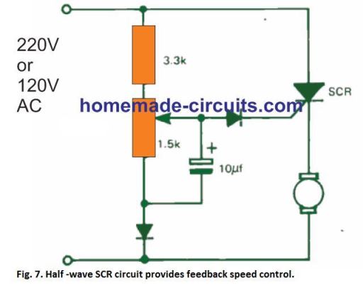
The circuit operates pretty good within a limited motor speed range although may be vulnerable to low-speed 'hiccups' and the half -wave working rule inhibits stabilized operation very much above the 50% speed range. A load sensing phase -control circuit where a Triac delivers complete zero to maximum control is displayed in Fig. 8.
Controlling Induction Motor Speed
Induction motors speed could be also controlled using Triacs, although you may come across a few difficulties particularly if split-phase or capacitor start motors are involved. Normally, induction motors could be controlled between full and half speed, given that these aren't 100% loaded.
The temperature of the motor could be used as a fairly dependable reference. The temperature should never go beyond the manufacturer's specifications, at any speed.
Yet again, the improved light dimmer circuit indicated in Fig. 6 above could be applied, however the load must be connected at the alternate location as revealed in the dotted lines
Varying Transformer Voltage through Phase Control
The circuit set up explained above could also be used to regulate the voltage within the primary side winding of a transformer thereby acquire a variable rate secondary output.
This design was applied in various microscope lamp controllers. A variable zero-set has been provided by changing the 47K resistor with a 100k potentiometer.
Controlling Heating Loads
The various Triac phase control circuits discussed until now may be applied to control heater type load applications, although the load temperature being controlled might change with variations in the input AC voltage and the surrounding temperature. A circuit that compensates for such varying parameters is demonstrated in Fig. 10.
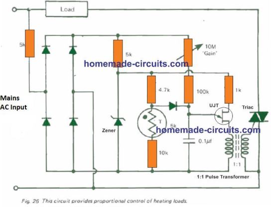
Hypothetically this circuit could keep the temperature stabilized to within 1% of the predetermined point regardless of AC line voltage alterations of +/-10%. Precise overall performance may be determined by the structure and design of the system where the controller is applied.
This circuit delivers a relative control, which means, total power is given to the heating load as the load is starting to warm up, then at some midway point, the power is lowered through a measure that's proportionate to the difference between the actual temperature of the load and the intended load temperature.
The proportional range is variable through a 'gain' control. The circuit is straightforward yet effective, however it includes one significant downside which limits its use to basically lighter loads. This issue is regarding the emission of heavy radio interference, due to triac phase chopping.
Radio Frequency Interference in Phase Control Systems
All triac phase control devices crank out huge amounts of RF disturbances (radio frequency interference or RFI). This fundamentally happens at lower and moderate frequencies.
Radio frequency emission is picked up strongly by all nearby medium wave radios and even by audio equipment and amplifiers, generating a irritating loud ringing sound.
This RFI could also impact research laboratory equipment, particularly the pH meters, resulting in unpredictable functioning of computers and other similar sensitive electronic devices.
A feasible remedy to reduce RFI is to add an RF inductor in series with the power line (indicated as L1 in the circuits). An appropriately dimensioned choke could be built by winding 40 to 50 turns of super enameled copper wire over a small ferrite rod or any ferrite core.
This may introduce an inductance of approx. 100 uH suppressing the RFI oscillations to a great extent. For increased suppression it might be essential to maximize the number of turns to as high as it may be feasible, or inductances up to 5 H.
Disadvantage of RF Choke
The downfall of this type of RF coil based triac phase control circuit is that the load wattage has to be considered according to the choke wire thickness. For the load is intended to be in kilowatt range then the RF choke wire has to be thick enough causing the size of the coil to increase significantly and bulky.
The RF noise is proportional to the load wattage, thus higher loads may cause higher RF emission demanding more improved suppression circuitry.
This issue may not be as severe for inductive loads like electric motors, since in such cases the load winding itself attenuates the RFI. Triac Phase control is also involved with an additional issue - that is the load power factor.
The load power factor may be negatively impacted and is an issue that power supply regulators regard quite seriously.

Questions & Answers
sir what is the number marking of UJT transistor given in fig 25 and winding details of pulse transformer please.
Hi Ravindran, it can be standard UJT, such as this one:
https://www.homemade-circuits.com/unijunction-transistor-ujt-2n2646-datasheet/
sir thanks for p e ovifing me the details requested by me. your service mind has developed many persons like me.
You are most welcome Ravindran, I am so glad you found it helpful…
hi can a triac be used to control a dc motor like in an electric train to have foreward and reverse and variable speed using a single potentiometer . and using a low voltage transformer i would like a typical schematic.
thank you
Hi, yes, a triac dimmer circuit can be used to control a DC motor through a transformer, by regulating the AC 220V or 120V across the primary side of the transformer through the triac dimmer.
The following circuits can be tried:
https://www.homemade-circuits.com/simple-ceiling-fan-regulator-circuit/
Hello Swagatam,
What are the components part number in figure 10.
Is it possible to used figure 10 for heating element.
Is the Maina AC 220 Volt.
I thank you.
greatings,
Haiwan
Hello Haiwan,
Which fig10 are you referring to? I cannot see any figure 10 in the above article?
Sorry Swagatam,
It is figure 26 from Controlling Heating Loads. In the above article
What are the components part number in figure 26.
Is it possible to used figure 10 for heating element.
Is the Mains AC 220 Volt.
gr,
Haiwan
Hi Haiwan,
Why do you want to use Fig26, it is big and inefficient.
You can simply use any circuit from the following article:
220V Light Dimmer and Ceiling fan Regulator Circuit [Using Triac and Diac]
Hallo Swagatam,
Thanks for you answer and I will used this.
gr
haiwan
You are welcome Haiwan.
Thanks I’ll try the recommended circuit first.
Hi Swagatam,
The circuit in fig.8 can you tell me what the value and wattages of the following components are please, – R5, Q2, is D6 a standard IN4007 , and the voltage of the 10uf electrolytic capacitor.
Would this circuit give smooth control for a treadmill motor and ac power tools?
Regards
Chris
Hi Chris,
Instead of the fig.6 I would recommend you the second schematic design from the following article which is similar in construction and has been tested by me. You can control all AC 220V or 120V power tools smoothly with this circuit. If your treadmill is AC operated then you can control its speed also with this circuit:
https://www.homemade-circuits.com/how-to-make-simplest-triac-flasher/
All the resistors are 1/4 watt 5%
Hi Swagatam;
I have tested a simple triac used dimmer circuit and measured the output result. At the output full limited position AC voltage is about let’s say 70 V not 0 V. Please advise if it is possible to gain so sensitive circuit as possible as enabling 220 to 0 V. Or please advise if it is possible to make a divider sensitive circuit for the voltages around AC 35 volts to AC 0 V. Best Regards
Hi Suat, you can reduce the minimum voltage by reducing the value of the resistor which is in series with the pot. But you should not reduce to a level where the output becomes zero, because then the light dimmer output will not initiate again until the pot pot is turned a long way.
Also if you are thinking of using the output for making a DC for using it for circuits then it is strictly not recommended because after rectification the output may rise to much higher level.
Hi, I was not sure where to put this comment. I have been using triac dimmer circuits like the circuits above with a bridge rectifier to run my drill press motors etc. It would be nice to have smoother control. I have several L622F power modules(SCR/Diode). I am unsure if there is a way to use these in a fairly simple dc motor control circuit.
https://www.sager.com/_resources/documents/product/Crydom-L513F.pdf
Hi, sorry, I am also not too sure how to configure these SCR bridge modules for smoothly controlling Dc motors.
Do you have a part number for T1 in figure 8 and can you speak a little more to its function? Also, for the unnamed coil in series with the motor?
Thanks for such a quick and detail answer. As they say down south, “Much obliged”.
Thank you, I am always glad to help!
T1 or Q1 is a UJT, you can try any small UJT in the circuit. Its function is t create oscillations for the gate of the triac via a pulse transformer.
The coil is a 1:1 pulse transformer, primary is connect to the UJT, and the secondary is connected to the triac gate.
Hi Swagatam, I’m stumped! I’ve a Dayton AC-DC Series 115V 1.5 Amp 1/10 Hp motor which is behaving strangely. The motor is controlled by a Dayton 5amp variable speed controller containing a RCA 65497 triac(this is 40 yrs old?). The motor is spinning in the opposite direction needed to turn a helical/spur gear(which drives a crank? this is a chiropractors thumper). the motor always rotates in the incorrect direction, there are two leads for power in, other than the ground, but when auto transformer rectified DC is powering it the motor will not reverse also if I power it by a 24V DC battery reversing the polarity does not reverse the direction of rotation! I’m not accustomed to this! Admitted my experience in working with speed controllers is limited, but can a bi-directional thyristor through phase change reverse a motor behaving this way? Mark
Hi Mark, That appears quite strange, because triac controllers are simply built to chop the AC and reduce the average power to the load, they have nothing to do with the motor polarity since they work with AC? You can try the variable speed controller with another motor and check if the same happens to the motor….that will confirm whether or not the triac driver is faulty?
Please correct the unit of the coil in fig 3 and 4 in Henry not Farad.
Thank you for notifying, I have added a correction message at the bottom of the images.