Refrigerators tend to draw appreciable amounts of current each time their compressor switch ON, and this could happen many times per day. A soft start circuit to the compressor motor could probably tackle this issue and help save electricity. The idea was requested by Mr. Naeem Khan.
Technical Specifications
I need your help regarding to control the starting torque(soft start) of the Refrigerator Compressor for energy saving purpose. All these compressor are capacitor start type. If you have any other idea to control these capacitor start compressor RPM then let me know.
Awaiting your reply soon.
The Design
The capacitor in a capacitor start motor has nothing to do with the speed of the motor. The capacitor is there just to energize the field coil of the motor for helping the main winding to start the rotation, after which it's cut-of from the system.
In any case, the soft start circuit presented here is irrelevant to the type of AC motor used, it should hopefully work for all types of motor.
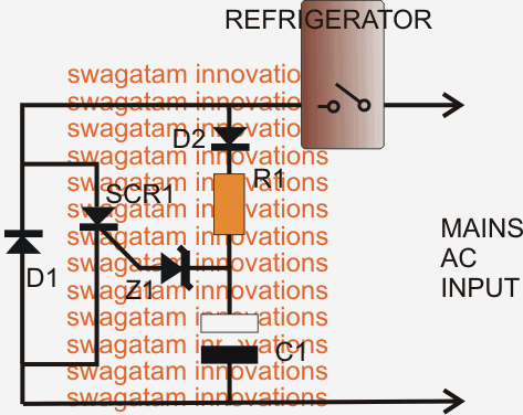
Referring to the figure we see an arrangement where the refrigerator is wired in series with a rectifier diode which has an SCR connected in parallel.
The operation is rather simple.
How the Circuit Operates
As soon as the internal relay of the refrigerator clicks ON, diode D1 provides a half wave AC to the refrigerator forcing a slow soft start to the motor, the SCR is unable to conduct immediately due to the the presence of the capacitor at its gate.
Therefore at the start, the refrigerator is able to get only a half wave AC through the rectifier diode, until the capacitor across the SCR gate/cathode charges up and fires the SCR.
During this period the half wave AC allows only around 50% of initial voltage to the refrigerator, providing a soft start to the motor, until within seconds the SCRs fires and restores full available power to the motor.
Once the SCR is fired it takes on the other half of the AC so that the refrigerator motor is able to gain its full rated torque.
Circuit Diagram
Parts List
R1 = 47K 1watt
D1 = 6 amp diode
D2 = 1N4007
Z1 = 50V 1 watt zener
C1 = 10uF/400V
Switch ON Starting Power Calculation
Since initially the series diode converts the AC input into a half wave DC, it's important to know the average DC applied at the particular instant. It may be calculated using the formula:
Vdc av = Vp/π
where π = 3.1416, and Vp = peak half wave value
The π value may be solved and the above formula may be further expressed as:
Vdc av = 0.318 Vp
The peak voltage may be calculated by using the following formula:
peak volts = RMS volts x 1.414
therefore we get:
Vp = Vrms x 1.414
For a 220V RMS, the above formula could be solved as:
Vp = 220 x 1.414 = 311.08V
For accuracy we can also include the 0.7V drop produced by the diode in our calculation:
Vdc av = (VP - 0.7)/π
Solving the above equation with Vp = 311.08, we get:
Vdc av = (311.08 - 0.7)/π = 98.84V
If the refrigerator motor coil resistance is known the above DC average voltage could be used for calculating the initial soft-start power consumed by the motor, through the following formula:
P = I2R, where P stands for power,
I = current (amps) and R = resistance of the motor coil
I (amps) could be found by applying Ohms law:
IDC = VDC /R,
where R = resistance of the motor coil, and VDC = 98.84V obtained from the previous calculations. where π = 3.1416.
Warning: The circuit has not been tested or verified practically, and the effects are unknown. Initially try the circuit by using a 200watt bulb. The bulb should brighten up slowly in comparison to when it's connected directly to mains.
Also the entire circuit is directly linked with mains and is therefore extremely dangerous while plugged in and without an enclosure.


Questions & Answers
Most of the refrigerators I have seen so far have an integrated motor – compressor. Yes, they are capacitive start but the motor is basically a vibrator and it works like a fish tank air bubbler (diaphram valve type). The compressor (about 100W or often less) draws high current because the capacitors need to be charged up and that takes only a few milliseconds. Adding a series inductor can help the inverter not to trip.
Thank you for the valuable feedback!
Hi, In your SCVR soft start circuit diagram I note under “SCR1” there is another diode (just before the Zener). Is my observation correct that there is a second diode and if so would it be the same value as D1? Regards
Hi, there are two diodes D1 and D2, whose values are given in the parts list!
Superb sir, I’ll try this to reduce the starting current of my fridge sir. Regards
Thanks Jerard, please note that the concept is not yet tested and confirmed practically
I would not be so quick to try this out without first doing it with a motor not connected to a Freon compressor. The reason being that these compressors must come up to speed within just a few tenths of a second. I installed a unit made by Emerson for their Copeland scroll compressor called SecureStart Part# 943-0120-00 on my 5T heat pump. It limits the inrush current to that of the LRA spec I think 7A. The sweet part is that it spins up the motor in the prescribed time to prevent damage to the equipment. They aren’t cheap but I can start my heat pump on my 10KW generator.
Hello, I tested the circuit, but never did soft start for my freezer, any other advice. I also tried the circuit on triac controlling inductive loads, same thing. Thanks
I don’t know the fault, but the current draw was even too high. Can you please help us test it to perfect the design. Thanks
the refrigerator is in series with the mains so whatever current draw you are seeing it is by your refrigerator only.
As you can see there’s hardly any component in the design and I have explained its working clearly which can be easily understood by anybody.
If you are having difficulty understanding it You can put this link to any electronic forum and ask their response about this and see if you can get an appropriate reply.
OK so what is the fault in the above design please tell us?
The fridge compressor motor has two windings, a start and run winding. They connect the start winding through a capacitor to AC (through the temperature control switch). The run winding connects to AC as well.
So your circuit is simply in-between the temperature controller and the compressor? Affecting both windings?
Yes I know the refrigerator compressor is a capacitor start motor. The circuit is only to prevent a sudden full voltage to the motor, rather a two step rising voltage within a span of may be milliseconds, but whether this is harmful or not to the motor only a motor expert can say!
Thank you for the quick response. I will test it and let you know what I find.
Hi, I have a boiler pump that would be better if it soft started so in a power failure so my inverter would not have to put a temporary surge off the battery I use. I am not sure this circuit will work, no one has built it yet and tested for me ? Some circuits use a triac do you have one that will work like the above circuit? Also, how do you test the breakdown voltage of a zener diode, I have a lot of them that are unmarked. Thank you
Hi, you could probably try the second circuit from the following post, it is not a tested one but it has to work, because the design concept looks very obvious and it cannot fail
https://www.homemade-circuits.com/adding-soft-start-to-water-pump-motors/
for identifying the zener voltage you can connect the respective zener across a DC voltage source through a 10K resistor, and measure the potential right across the zener diode pins, this will give you the required data regarding the device.
hi Swagatam , and thanks for sharing such elegant idea , I was wondering if received any feedback from any user that used your idea? actually I'm Arduino fan and control the home appliance is one of my biggest fun , I read couple of inverter open source to have full control over the AC motors , but my Idea have change due to it may not economical , then I decided to follow the way which control the motor in 2 or 3 different speed and not 0 to 100 % full control anymore , also your elegant way to soft starting motor is quite fascinating for me to implement it , I hope have your advise to start such practical project
best regards
Dear Swagatam,
In the motor soft start circuit for the refrigerator, you did not specify the type of the thyristor to be used. Are we free to use any type of thyristor.
Regards
Bernard Tendengu
Dear Bernard, you can try using a BT151.
Hi,
Another doubt, when we use a diode in series with a load, it gets half of the supply voltage. So the power consumption reduces to 1/4 ie. 25% not 50%, if voltage reduces to 1/3, the power reduces to 1/9 so
I have added the required info for your reference….
I have only tried to present a general concept quickly, the critical aspects and conditions will need to be calculated, confirmed by the user while making the practical design.
Hi,
Have you tested this circuit? I think capacitor start induction run motor is used in the compressors, (if you use a lamp, it will glow) such motors do start or run in half or full wave DC ( only universal motors, used in mixie, power tools etc; can start/ run in AC as well as DC
Hi,
Please read the warning message at the bottom, I have clearly mentioned my doubts there.
I have given the example of a bulb just to make sure nothing goes in smoke while using it with any other form of load.
Hi Swagatam
Would you please provide the specs of the SCR?
Hi Abu-Hafss,
We can try BT151, I think it would work for the above application, its RMS current handling capacity is only 4 amps but since the initial surge is sinked by the diode, the scr would stay aloof from it.