Here I have explained four best electronic thermometer circuits which can be universally used for measuring body temperatures or atmospheric room temperatures ranging from zero degrees to 50 degrees Celsius.
In the previous post I explained some of the features of the outstanding temperature sensor chip LM35, which gives outputs in varying voltages that's directly equivalent to ambient temperature changes, in Celsius.
This feature in particular makes the construction of the proposed room temperature thermometer circuit very simple.
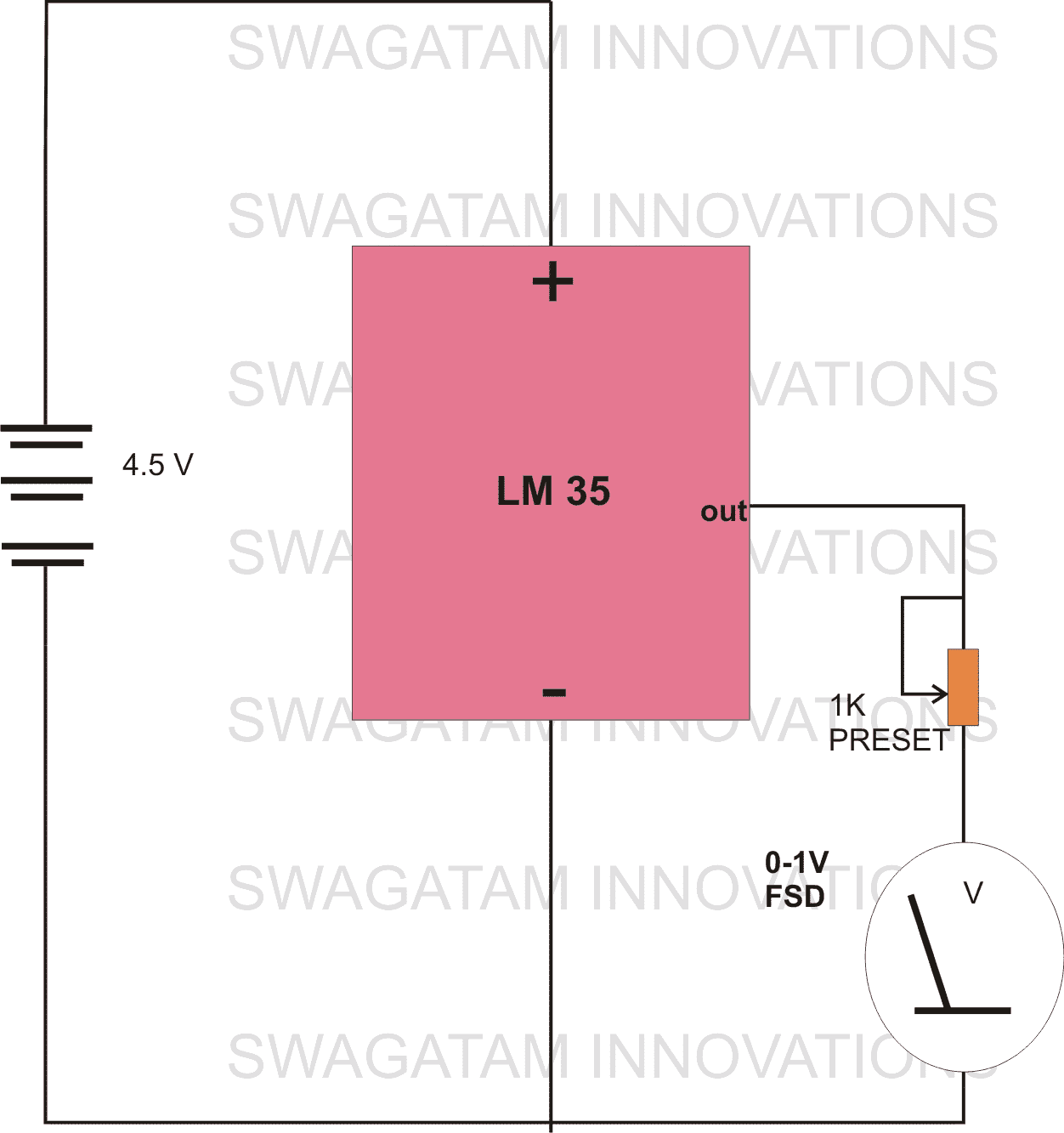
1) Electronic Thermometer using a Single IC LM35
It just requires a single IC to be connected with a suitable moving coil type of meter, and you start getting the readings almost immediately.
The IC LM35 will show you a 10mv rise in its output volts in response to every degree rise in the temperature of the atmosphere surrounding it.
The circuit diagram shown below explains it all, no need of any complicated circuitry, just connect a 0-1 V FSD moving coil meter across the relevant pins of the IC, set the pot appropriately, and you are ready with your room temperature sensor circuit.
Setting up the unit
After you have assembled the circuit and finished doing the shown connections, you may proceed with the setting of the thermometer as I have explained below:
- Put the preset in the midway range.
- Switch ON the power to the circuit.
- Take a bowl of melting ice and immerse the IC inside the ice.
- Now carefully start adjusting the preset, such that the meter reads a zero volts.
- The setting up procedure of this electronic thermometer is done.
Once you remove the sensor from the ice, within seconds it will start displaying the present room temperature over the meter directly in Celsius.
2) Room Temperature Monitor Circuit
The second electronic thermometer design below is another very simple yet highly precise air temperature sensor gauge circuit has been presented here.
The use of the highly versatile and accurate IC LM 308 makes the circuit respond and react superbly to the smallest temperature changes happening over its surrounding atmosphere.
Using the Garden Diode 1N4148 as the Temperature Sensor
Diode 1N4148 (D1) is used as an active ambient temperature sensor here. The unique drawback of a semiconductor diode such as a 1N4148 which shows forward voltage characteristic change with the influence of ambient temperature change has been effectively exploited here, and this device is used as a efficient, cheap temperature sensor.
The electronic air temperature sensor gauge circuit presented here is very accurate in its function, categorically due to its minimum level of hysteresis.
Complete circuit description and construction clues included herein.
Circuit Operation
The present circuit of an electronic air temperature sensor gauge circuit is outstandingly accurate and can be very effectively used to monitor the atmospheric temperature variations. Let’s briefly study its circuit functioning:
Here as usual we use the very versatile “garden diode” 1N4148 as the sensor due to its typical drawback (or rather an advantage for the present case) of changing its conduction characteristic in the influence of a varying ambient temperature.
The diode 1N4148 is comfortably able to produce a linear and an exponential voltage drop across itself in response to a corresponding increase in the ambient temperature.
This voltage drop is around 2mV for every degree rise in temperature.
This particular feature of 1N4148 is extensively exploited in many low range temperature sensor circuits.
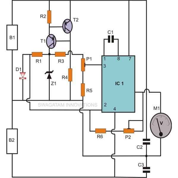
Referring to the proposed room temperature monitor with indicator circuit diagram given below, we see that, IC1 is wired as an inverting amplifier and forms the heart of the circuit.
Its non inverting pin # 3 is held at a particular fixed reference voltage with the help of Z1, R4, P1 and R6.
Transistor T1 and T2 are used as a constant current source and helps in maintaining higher accuracy of the circuit.
The inverting input of the IC is connected to the sensor and monitors even the slightest change in the voltage variation across the sensor diode D1. These voltage variations as explained, is directly proportional to the changes in the ambient temperature.
The sensed temperature variation is instantly amplified into a corresponding voltage level by the IC and is received at its output pin #6.
The relevant readings are directly translated into degree Celsius through a 0-1V FSD moving coil type meter.
Parts List
- R1, R4 = 12K,
- R2 = 100E,
- R3 = 1M,
- R5 = 91K,
- R6 = 510K,
- P1 = 10K PRESET,
- P2 = 100K PRESET,
- C1 = 33pF,
- C2, C3 = 0.0033uF,
- T1, T2 = BC 557,
- Z1= 4.7V, 400mW,
- D1 =1N4148,
- IC1 = LM308,
- General Purpose Board as per size.
- B1 and B2 = 9V PP3 battery.
- M1 = 0 – 1 V, FSD moving coil type voltmeter
Setting Up the Circuit
The procedure is a bit critical and requires special attention. To complete the procedure you will need two accurately known temperature sources (hot and cold) and an accurate mercury-in-glass thermometer.
The calibration may be completed through the following points:
Initially keep the presets set at their midways. Connect a voltmeter (1 V FSD) at the output of the circuit.
For the cold temperature source, water at about room temperature is used here.
Dip the sensor and the glass thermometer into the water and record the temperature in the glass thermometer and the equivalent voltage outcome in the voltmeter.
Take a bowl of oil, heat it to about 100 degrees Celsius and wait until its temperature stabilizes down to about 80 degrees Celsius.
As above, immerse the two sensors and compare them with the above result. The voltage reading should be equal to the temperature change in the glass thermometer times 10 mill volt. Didn’t get it? Well, let’s read the following example.
Suppose, the cold temperature source water is at 25 degrees Celsius (room temperature), the hot source, as we know is at 80 degrees Celsius. Thus, the difference or the temperature change between them is equal to 55 degrees Celsius. Therefore the difference in the voltage readings should be 55 multiplied by 10 = 550 mill volts, or 0.55 volts.
If you don’t quite get the criterion satisfied, adjust P2 and continue to repeat the steps, until finally you achieve it.
Once the above rate of change (10 mV per 1 degree Celsius) is set, just adjust P1 so that the meter shows 0.25 volts at 25 degrees (sensor held in water at room temperature).
This concludes the setting of the circuit.
This air temperature sensor gauge circuit can also be effectively used as an room electronic thermometer unit.
3) Room Thermometer Circuit using LM324 IC

The 3rd design is probably the best one as far as cost, ease of construction and accuracy is concerned.
A single LM324 IC, a 78L05 5V regular IC and a few passive components are all that is needed to make this easiest room Celsius indicator circuit.
Only 3 op amps are used from the 4 op amps of the LM324.
Op amp A1 is wired to create a virtual ground for the circuit, for its effective working. A2 is configured as a non-inverting amplifier where the feedback resistor is replaced with a 1N4148 diode.
This diode also acts as the temperature sensor, and drops around 2 mV from every single degree rise in the ambient temperature.
This 2 mV drop is detected by the A2 circuit and is converted into a correspondingly varying potential at pin#1.
This potential is further amplified and buffered by A3 inverting amplifier for feeding the attached 0 to 1V volmeter unit.
The voltmeter translates the temperature dependent varying output into a calibrated temperature scale to produce the room temperature data quickly through the relevant deflections.
The entire circuit is powered by a single 9 V PP3.
So folks, these were 3 cool, easy to build room temperature indicator circuits, that any hobbyist can build for monitoring the ambient temperature variations of a premise quickly and cheaply using standard electronic components, and without involving complex Arduino devices.
4) Electronic Thermometer Using IC 723
Just as the above design here too a silicon diode is employed like a temperature sensor. The junction potential of a silicon diode goes down by approximately 1 millivolt for each degree centigrade, which allows temperature of the diode to be determined by calculating the voltage over it.
When configured as a temperature sensor, a diode offers the benefits of high linearity with a low time constant.
It could additionally be implemented over a broad temperature range, from -50 up to 200 C. As the diode voltage needs to be assessed quite accurately, a reliable reference supply is necessary.
A decent option is the IC 723 voltage stabilizer. Even though absolute ti value of the zener voltage within this IC can be different from IC to another, the temperature coefficient is extremely small (typically 0.003% per degree C).
In addition, the 723 is known to stabilize the 12 volt supply throughout the circuit. Observe that the pin numbers in the circuit diagram are only suitable for the dual -in - line (DIL) variant of the IC 723.

The other IC, the 3900, includes quad amplifiers where just a couple of are utilized. These op amps are designed to work a little differently; these are configured as current driven units instead of as voltage driven. An input could best be considered to be the transistor base in a common-emitter configuration.
As a result, the input voltage is often around 0.6 volt. R1 is coupled to the reference voltage and a constant current hence moves through this resistor.
Due to its large open loop gain, the op amp is able to adapt its very own output in order that the exact same current runs into its inverting input, and the current through the temperature -sensing diode (D1) thus stays constant.
This set up is important due to the fact the diode is, essentially, a voltage source having a specific internal resistance, and any kind of deviation in the current moving via it might as a result create a variation in the voltage which could end up being erroneously translated as a variation in temperature.
The output voltage at pin 4 is hence the same as the voltage at the inverting input as well as the voltage around the diode (the latter changing with temperature).
C3 inhibits oscillation. Pin 1 of IC 2B is attached to the fixed reference potential and a constant current consequently moves into the non inverting input. The inverting input of IC 2B is hooked up by means of R2 to the output of IC 2A (pin 4), in order that it is operated by a temperature-dependent current. IC 2B amplifies the difference between its input currents to a value that the voltage deviation at its output (pin 5) could quickly be read with a 5 to 10 volt f.s.d. voltmeter.
In case a panel meter is employed, Ohm's law may need to be configured to determine the series resistance. If a 100-uA f.s.d. meter with an internal resistance of 1200 is employed, the total resistance for 10 V full-scale deflection has to be as per the calculation:
10/ 100uA = 100K
R5 must as a result be 100 k - 1k2 = 98k8. The closest common value (100 k) will work well. Calibration can be done as I have explained below: the zero point is initially fixed by P1 using the temperature sensor immersed in a bowl of melting ice.
Full-scale deflection can after that be fixed with P2; for this the diode can be submerged inside hot water whose temperature is identified (let's say boiling water tested with any standard thermometer to be at 50°).
Using CA3130 IC
This thermometer has a linear scale and provides the temperature range of 0 to 50 degrees Celsius, allowing it to be read straight from a 50uA meter. By inserting a 100uA meter, a temperature range of 0-100 degrees Celsius may be established.
The temperature sensors in the unit are silicon diodes D1 and D2, which are typically put inside some sort of probe that can be deployed several meters away from the other electronics if required. C1 eliminates noise detected through the connecting cable.
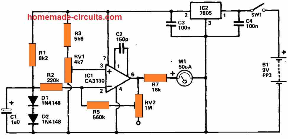
R1 provides a slight forward bias to D1 and D2, such that there is no substantial self heating of the diodes. The voltage generated between the diodes is theoretically 1V2, but it changes by around 2mV per degree C per diode, or approximately 4mV through both diodes.
This voltage is applied to the input of an operational amplifier inverting amplifier, IC1. RV1 is set for the greatest voltage at IC1's non-inverting input that provides zero output voltage when the probe is at 0 degrees C (which may be obtained by dipping the probe in ice).
This provides the required compensation for the quiescent voltage across the diodes and results in a 0 V display on the 1V FSD voltmeter circuit hooked up across the amplifier's output.
When the diodes become warm up to to 50 degrees Celsius, the voltage across them drops by around 200mV, which is boosted by the amplifier through a factor of 5 to provide around 1V at its output, which results nearly a full scale meter deflection.
Practically, RV2 is utilized to tune the amplifier's gain such that full scale deflection is generated.
RV2 can, obviously, be adjusted to the proper temperature using the probe at any specified temperature that translates to a significant meter deflection.
The circuit demands highly steady supply of around 5V, which may be achieved with a 5V monolithic regulator and a 9V battery (IC2). To avoid instabilities, C3 and C4 should must be positioned near to IC2.
Thermometer using 10 LED Bar Graph Display
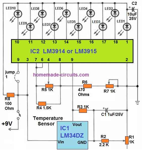
The 10 LED bar graph thermometer discussed below is ideal for applications requiring room temperature measurements.
It uses ten LEDs in a bar graph mode to display the temperature in steps of two degrees each. The total range is around 60 to 78 degrees Fahrenheit.
By illuminating either just the relevant LED or all the 10 LEDs, the circuit may be configured to show temperature like a bar graph.
The circuit is operated by a 9-volt battery in the illustration, however it could work with any DC power source between 7 and 10 volts.
The IC1, an LM34 temperature sensor, forms the mind of the thermometer. In between Vout and GND terminals, that LM34 generates a voltage that is directly equivalent to the detected temperature changes.
Despite the fact that the output of LM34 is typically 10 millivolts per degree Fahrenheit, it is configured with a resistor network using R1-R3 with a gain that produces an output of 40 mV/°F.
Between R1 and R2, capacitor C1 serves as a noise bypass. Potentiometer R1 must be precisely adjusted since the voltage generated by IC1 would be utilized by the whole circuit to "judge" the room temperature precisely.
The real voltage to temperature takes place at pin 5 of IC2, which is the LM3914 LED bar or dot graph driver. This pin receives the detected output from IC1 in mV.
This is how it functions: Ten internal comparators in IC2 are linked to LEDs 1 to 10 via their output pins. IC2 compares the IC1 voltage at its pin 5 with the reference voltages at its pins 4 and 6. This results in the sequential illumination of the LEDs according to increasing or decreasing temperature levels.
The jumper connection at pin#9 of IC2 determines whether the LEDs will run individually or in a bar graph mode.
Keeping the jumper connected with pin#9 allows the LEDs to illuminate in the bar graph mode.
How to Calibrate
The three potentiometers should be first adjusted to somewhere around the middle of their ranges. After that, attach a 9V battery to the circuit and switch the device on.
Use a DVM or an analogue VOM with a 1% accuracy or better to obtain the following measurements after a couple minutes of warm-up time. Connect the meter's positive probe to IC2's pins 6 and 7, then hook its negative wire to the circuit's ground.
Next, adjust Potentiometer R7 until the meter reads 3.345 volts or a value which may be as near to this as possible.
After that, join the positive probe of the meter to IC2's pin 4 and set potentiometer R5 to a value of 2.545 volts, being careful to set it as precisely as you can.
After that, take a temperature reading of the atmosphere as close as possible to IC1 using a standard thermometer which is considered to be relatively accurate.
Photo thermometers intended for use in darkrooms work well for this as they are often regulated at 68°F.
Adjust potentiometer R1 using the above temperature reading as a reference until the appropriate LED for that temperature illuminates (if the circuit is set to operate in bar mode, then all the LEDs up to the corresponding one should also illuminate).
Now, evaluate the potential difference between IC2 pin 5 and ground. It should roughly match the result of the following equation:
V = 0.225 + (0.04 x T),
where V is the potential at IC2 pin 5 and T is the temperature in degrees Fahrenheit.
In order to calibrate R1 without a thermometer, perform these steps: Detach both the ICs from the circuit and turn off the power. Then, calculate the resistance (R3) in ohms using a precise ohmmeter; remember that value. After this, attach the ohmmeter across R1.
R1 should be configured so that a value that is precisely three times R3 is achieved. Restore IC1 and IC2 to complete the process.
Thermometer for Indicating in Centigrade
If you have a thermometer which can produce temperature indications directly in centigrade, then the following design can prove useful.
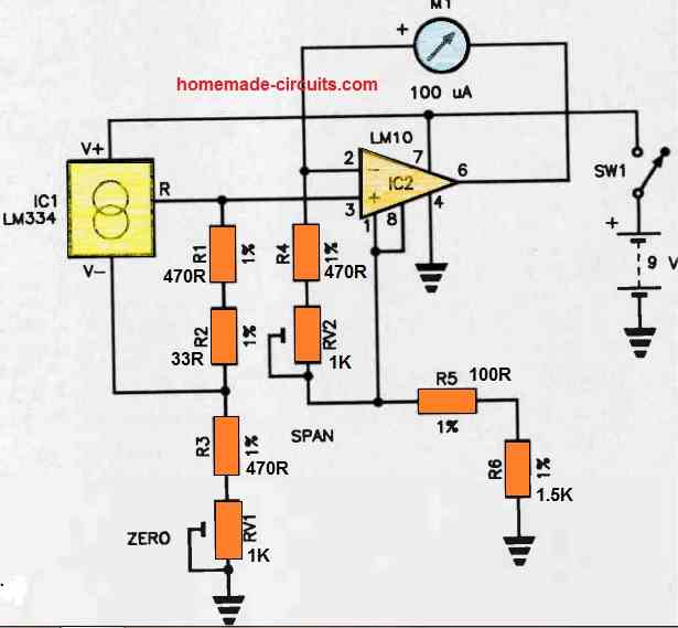
The LM334 precision current source/temperature sensor from NATIONAL Semiconductors serves as the foundation for an excellent 0-100 degree Celsius thermometer.
It supplies a variable voltage input to the LM10 (IC2) precision op-amp in this circuit.
The resistor network made up of R1, R2, R3, and RV1 supplies the LM334 with the necessary bias, with RV1 establishing the zero degree point.
As the meter is a part of the IC2 feedback network, R4-RV2 define the feedback, and as a result, RV2 determines the highest possible temperature range, or span. Make sure to use only 1% resistors and cermet trimpots.
To calibrate the thermometer, immerse IC1 into freshly melted ice for the zero degree centigrade point and freshly boiling water for the 100 degree centigrade point.


Questions & Answers
Thanks so far Swag.
I have started work on the “Room Thermometer Circuit using LM324 IC’ project. I just want to know if A1, A2 and A3, in the diagram, stands for pins 1, 2 and 3 of LM324 IC
Thank you Lisborn,

A1, A2, A3 are any 3 op-opam modules from the LM324 IC, there are 4 of them in all, and we select and use only 3 of them:
Mr Swagatam
I ask for help in a temperature control using a triac for some 3000w
of a hydromassage tank.
appreciate
Luiz
Hello Mr. Luiz, you can try the concept presented in the following article:
https://www.homemade-circuits.com/how-to-make-simplest-triac-flasher/
Make sure to Replace the triac with BTA41A and use a large heatsink on the triac
Mr. Swagatam
I am a very old electronics technician graduated in 1958 I am now 79 years old I see many good
projects I am always accompanied and I congratulate you for this site and all your work
thankful
luiz giannatasio
Thank you Mr. Luiz, I am glad you liked this website, appreciate your kind feedback.
peço desculpa formulei mal meu pedido ele é 3000w mas deve manter constante uma temperatura em torno de 35 graus c
agradeço muito
luiz giannatasio
de Brasil sp
OK, in that case you can try this egg incubator concept, which is designed to keep the ambient temperature fixed at a specified temperature, as per the setting of the op amp preset.
how do I add a 7 segment display to the circuit for both negative and positive temperature display?
you can integrate the following circuit with the above for getting a digital readout
https://www.homemade-circuits.com/2013/05/make-this-simple-digital-voltmeter.html
Hlw.. I NeeD ur help.
1.how to make a 12V 10A DC Fan speed controlr?
2.how to make room temperature meter?
you can try the following:
https://www.homemade-circuits.com/2012/05/make-this-pwm-based-dc-motor-speed.html
Hi Swagatam !!!
I can't see any thermistor
how the ic will sense rise in temperature
Hi Asif, the LM35 itself a temperature sensor, we don't need a thermistor here
I like them circuits SWAGATAM,
congratulations.
thanks! you are welcome.