Have you ever turned up your amplifier all the way, either at a party or just for fun? You may have noticed that "it gets hot" and thought that a fan would be useful. However, at low listening levels, you can hear the fan running. With this circuit, the fan will be automatically controlled by a relay within a certain temperature range. You can adjust the fan activation and deactivation thresholds as you wish and no longer worry about it at all: it will work perfectly and ensure the proper functioning of your device in all circumstances.
Examining the Fan ON/OFF Timing Graph
Let's examine, if you will, the philosophy behind this control module and observe, to do so, the diagram in Figure 1:
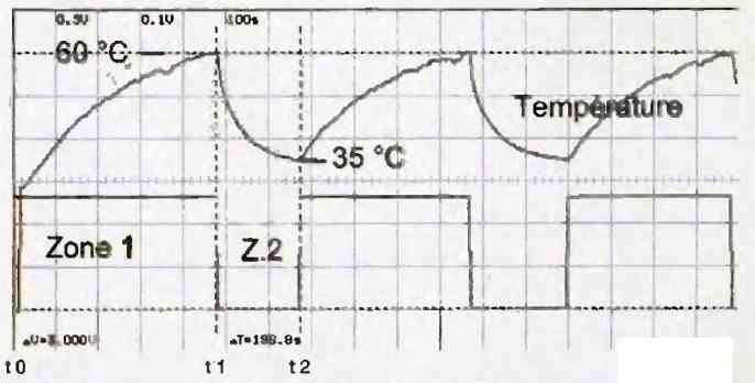
At time t0, you turn on your amplifier, put a good record on the turntable, and turn up the volume to a comfortable listening level. After a few minutes, the air inside the enclosure (which you want to cool) heats up.
This means that some of the energy is being dissipated as heat. We will control the fan using the normally closed contact of a relay to avoid increasing the dissipation.
When the temperature reaches a certain value (detected by a thermistor), the fan starts to turn at time t1, when the temperature threshold 1, which is 60°C, is reached.
The fan begins to draw the hot air out of the enclosure, thus lowering the temperature. When the temperature crosses the threshold 2 (35°C) at time t2, the fan stops turning.
The temperature rises again, the fan starts again, and so on, completely automatically.
The bottom curve represents the state of the comparator output. The fan runs in zone 2, while it is inactive in zone 1.
How the Circuit Works
In Figure 2 below, you will find the circuit diagram of this module.
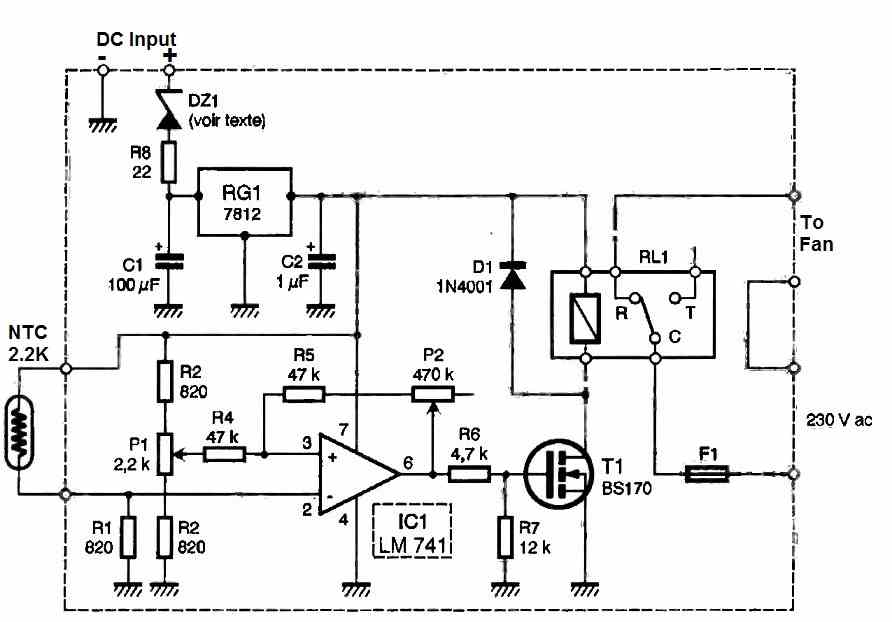
The NTC (Negative Temperature Coefficient) resistor detects the temperature at a hot spot of the device to be cooled.
When combined with resistor R1, it generates a voltage that increases as the temperature increases (since the resistance of the NTC decreases).
This voltage is applied to the input of an operational amplifier configured as a comparator. The combination of resistors R2, R3, and potentiometer P1 allows for an adjustable threshold voltage using P1.
The combination of resistors R4, R5, and potentiometer P2 allows for an adjustable hysteresis effect using P2. The larger the hysteresis, the greater the difference between the two aforementioned thresholds, and vice versa.
In the example of Figure 1, we measured thresholds of 7.84V (corresponding to the activation of the fan) and 5.76V (corresponding to its deactivation).
The output of the comparator, which analyzes the situation with respect to the temperature to be monitored, controls a relay through the switching transistor T1.
Power Supply Configuration
As this circuit is intended to be incorporated into any power amplifier, we have equipped it with a universal power supply circuit that must be adapted to your personal amplifier.
To do this, simply determine the value of the supply voltage on which you will power your module (i.e., V+ supply) in order to determine the value of zener diode DZ1.
This diode allows for the input voltage of regulator RG1 to be reduced to a reasonable level. The formula to be applied is as follows:
Vdz1 = (V+ supply - 18) volts.
Let's take an example:
At full power, the supply voltage V+ supply, which can be obtained from the filter capacitor or elsewhere, is 42V. The zener voltage of DZ1 will be:
Vdz1 = (V+ supply - 18)V = (42 - 18)V = 24V.
In this case, a 24V, 1.3W power zener diode should be used.
If your amplifier already has a 12V voltage, you can of course skip this power supply section and directly connect your 12V to the terminals of capacitor C2.
The consumption of our module ranges from 10mA to 42mA depending on the state of the relay (idle or working).
Construction
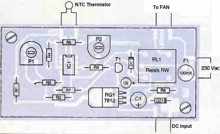
Figure 3 shows the printed circuit board layout. Component placement can be done with the help of Figure 4.
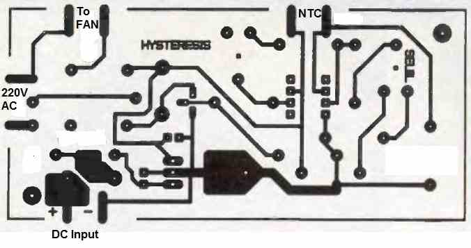
This circuit uses only very common components, and no difficulties should be encountered in building this small module.
The input and output leads should be connected to the corresponding copper tabs.
The length of wire between the NTC and the module should be kept as short as possible. If this length exceeds 30 cm, shielded wire should be used (connect the shielding to +12V).
A fuse protects the relay contacts in case of accidental short-circuit.
Finally, two 3mm holes allow the module to be securely fastened using screws and standoffs.
How to Test
To test the module, apply power and position the potentiometer sliders in the center:
- The relay should be released at room temperature.
- Heat the NTC with a soldering iron; at a certain temperature, the relay should switch.
Another, quicker method is to short-circuit the NTC to put the relay in its released state, and to short-circuit resistor R1 to put it into its activated state.
Remember that the fan is switched by the normally-open relay contact, and therefore it will not run when the relay is not active.
Arduino based Temperature Controlled DC Fan Circuits
In the next articles below, I will show how to construct a couple of simple Arduino based automatic temperature controlled dc fan circuits which will switch ON a fan or any other gadgets connected to it, when the ambient temperature reaches a pre-determined threshold level. We are going to utilize DHT11 sensor and arduino for this project.
Overview
The beauty of microcontrollers is that, we get very precise control over the peripherals which are connected to it. In this project the user just need to input the threshold temperature in the program, the microcontroller will take care of rest of the function.
There are tons of non-microcontroller based automatic temperature controller projects available around the internet, such as using comparator and transistors.
They are very simple and they do work well but, the problem arises while calibrating the threshold level using preset resistor or potentiometer.
We have a blind idea while calibrating it and the user may need to do trial and error method to find the sweet spot.
These problems are overcome by microcontrollers, the user just need to enter the temperature in Celsius in this project, so no need for calibration.
This project can be used where internal temperature of circuit need to be stabilized or saving it from overheating.
In diagram 1, we are connecting a CPU fan as output. This setup can be used to control the internal ambient temperature of an enclosed circuit.
When the threshold temperature is reached the fan turns on. When the temperature goes below threshold temperature fan turns off. So it’s basically an automated process.
In diagram 2, we connected a relay for controlling devices which runs on mains voltage such as table fan.
When the room temperature reaches the threshold temperature the fan turns on and turns off when the room cools down.
This may be the best way for saving power and this can be heaven for lazy people who wish others to switch the fan ON when they feel warm.
Circuit Diagram Showing a DC Fan Control
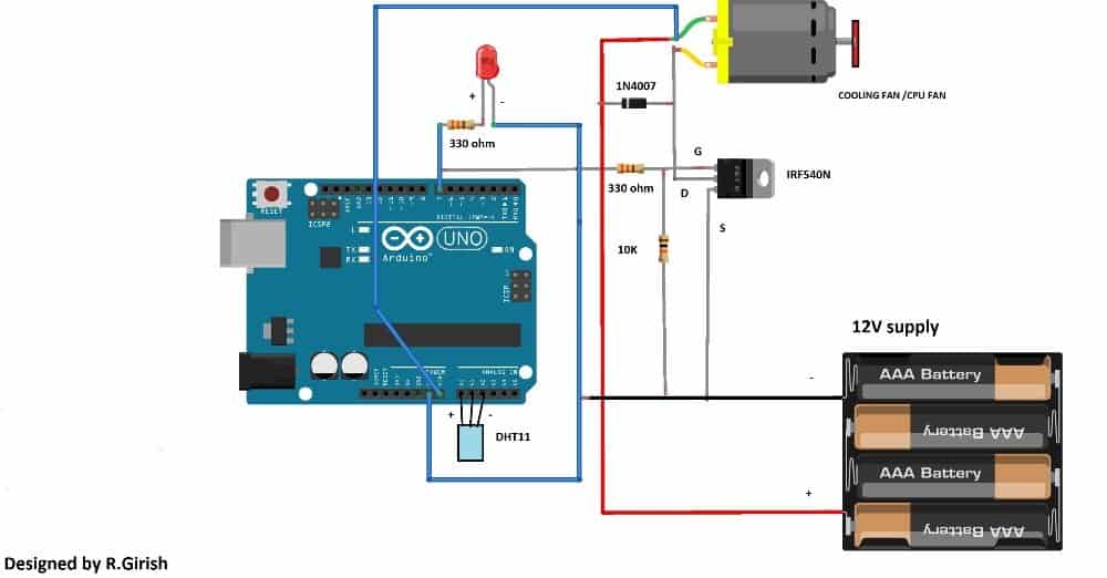
This setup may be deployed for circuits which are enclosed in a box. The LED turns ON when the preset threshold level reached and also turns ON the fan.
Connecting a Relay for Controlling Bigger Fans
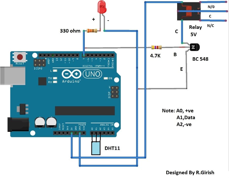
This circuit does the similar function of previous circuit, now the fan is replaced by relay.
This circuit can control a table fan or ceiling fan or any other gadget which can cool down the ambient temperature.
The connected device turns off as soon as the temperature reached below preset threshold level.
The temperature controlled dc fan circuit diagram illustrated here are just few of many possibilities. You may customize the circuit and program for your own purpose.
NOTE 1: #Pin 7 is output.
NOTE 2: This program is only compatible with DHT11 sensor only.
Program for the above explained automatic temperature regulator circuit using Arduino:
Program Code
//--------------------Program developed by R.Girish---------------------//

#include <dht.h>

dht DHT;

#define DHTxxPIN A1

int p = A0;

int n = A2;

int ack;

int op = 7;

int th = 30; // set thershold tempertaure in Celsius

void setup(){

Serial.begin(9600); // May be removed after testing

pinMode(p,OUTPUT);

pinMode(n,OUTPUT);

pinMode(op,OUTPUT);

digitalWrite(op,LOW);

}

void loop()

{

digitalWrite(p,1);

digitalWrite(n,0);

ack=0;

int chk = DHT.read11(DHTxxPIN);

switch (chk)

{

case DHTLIB_ERROR_CONNECT:

ack=1;

break;

}

if(ack==0)

{

// you may remove these lines after testing, from here

Serial.print("Temperature(°C) = ");

Serial.println(DHT.temperature);

Serial.print("Humidity(%) = ");

Serial.println(DHT.humidity);

Serial.print("\n");

// To here

if (DHT.temperature>=th)

{

delay(3000);

if(DHT.temperature>=th) digitalWrite(op,HIGH);

}

if(DHT.temperature<th)

{

delay(3000);

if(DHT.temperature<th)digitalWrite(op,LOW);

}

}

if(ack==1)

{

// may be removed after testing from here

Serial.print("NO DATA");

Serial.print("\n\n");

// To here

digitalWrite(op,LOW);

delay(500);

}

}

//-------------------------Program developed by R.Girish---------------------//
Note: In the program
int th= 30; // set the threshold temperature in Celsius.
Replace “30” with the desired value.
Second Design
The second temperature controlled dc fan circuit project discussed below automatically senses the ambient temperature and adjusts the fan motor speed to keep the surrounding temperature under control. This automatic processing is done through an Arduino and a temperature sensor IC LM35.
By: Ankit Negi
OUR OBJECTIVE:
1). As soon as temperature of the surrounding increases beyond 25 degree Celsius (you can change this value in program according to your need, explained in working section) motor starts running.
2). And with each degree of rise in temperature, speed of motor also increases.
3). Motor run at its top speed as soon as temperature rises to 40 degree Celsius ( this value can be changed in program).
TEMPERATURE SENSOR LM35:
To achieve the task mentioned above, we are going to use temp. Sensor LM35 as it is used widely and easily available.
LM35 has 3 pins as you can see in figure.
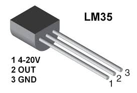
1. Vin-- this pin is connected to dc power supply between 4 to 20 v.
2. Vout-- this pin gives output in the form of voltage.
3. GND-- this pin is connected to gnd terminal of circuit.
LM35, when connected to power supply senses the temperature of surroundings and sends equivalent voltage in accordance with per degree rise in temperature through its output pin.
LM35 can sense any temp. between -50 degree to +150 degree Celsius and increases output by 10 millivolts with 1 degree rise in temperature. Thus maximum voltage it can give as output is 1.5 volts.
WHY ARDUINO FOR THIS DC FAN CONTROLLER PROJECT?
Arduino is required to change the analog value received from output pin of LM35 to digital value and sends the corresponding digital output (PWM) to the base of mosfet.
We will also use arduino commands to print temperature, corresponding analog value and digital output to mosfet on serial monitor of ARDUINO IDE.
WHAT IS THE ROLE OF POWER MOSFET?
This circuit will be of no use if it cannot run high current motor. Hence to run such motors power mosfet is used.
WHY DIODE IS USED?
Diode is used to protect the mosfet from the back E.M.F generated by motor while running.
PARTS LIST FOR THE PROJECT:
1. LM35
2. ARDUINO
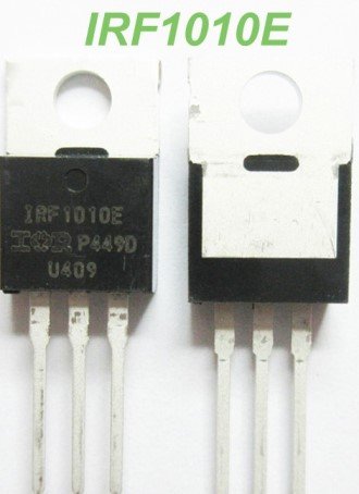
3. POWER MOSFET ( IRF1010E)
4. DIODE (1N4007)
5. FAN (motor)
6. FAN POWER SUPPLY
CIRCUIT DIAGRAM:
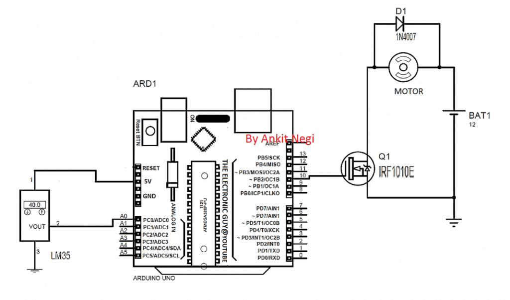
Make connections as shown in circuit diagram.
a) Connect vin pin of lm358 to 5v of arduino
b) Connect vout pin of lm358 to A0 of arduino
c) Connect ground pin of lm358 to GND of arduino
d) Connect base of mosfet to PWM pin 10 of arduino
CODE:
float x;// initialise variables

int y;

int z;

void setup()

{

pinMode(A0,INPUT); //  initialize analog pin A0 as input pin

Serial.begin(9600); // begin serial communication

pinMode(10,OUTPUT); //  initialize digital pin 10 as output pin

}

void loop()

{

x=analogRead(A0) ; // read analog value from sensor's output pin connected to A0 pin

y=(500*x)/1023;// conversion of analog value received from sensor to corresponding degree Celsius (*formula explained in working section)

z=map(x,0,1023,0,255) ; // conversion of analog value to digital value

Serial.print("analog value    ");

Serial.print(  x) ; // print analog value from sensor's output pin connected to A0 pin on serial monitor( called "analog value")

Serial.print("    temperature    ");

Serial.print(  y) ; // print the temprature on serial monitor( called "temprature")

Serial.print("     mapped value     ");

Serial.print(      z*10) ; // multiply mapped value by 10 and print it ( called " mapped value " )

Serial.println();

delay(1000) ; // 1 sec delay between each print.

if(y>25)

{analogWrite(10,z*10)  ;  // when temp. rises above 25 deg, multiply digital value by 10 and write it on PWM pin 10 ( ** explained in working section)

}

else

{analogWrite(10,0) ; //  in any other case PWM on pin 10 must be 0

}

}
WORKING (understanding code):
A). VARIABLE X-
This is simply the analog value which is received by pin no. A0 from the output pin of LM35.
B). VARIABLE Y-
Because of this variable only, our fan motor runs in accordance with the corresponding temperature. What this variable does is it changes the analog value i.e. variable x to corresponding temperature of surroundings.
Y = (500*x)/1023
1. First analog value must be changed to corresponding voltage i.e.
1023: 5v
Hence, (5000 millivolt *x)/1023 V
2. Now we know that for each degree rise in temperature corresponding voltage output increases by 10 mv i.e.
1 degree Celsius: 10 millivolts
Hence, (5000 millivolt *x)/ (1023*10) DEGREE
C). VARIABLE Z-
z=map(x, 0, 1023, 0,255) ;
this variable changes the analog value to digital value for pwm output on pin 10.
NOTE:: We know that lm35 can provide maximum of 1.5 volt and that too when temp. Is 150 deg. which is not practical.
This means for 40 degree Celsius we get 0.40 volts and for 25 degree we get 0.25 volts. Since these values are very low for proper pwm on mosfet, we need to multiply it by a factor.
Hence we multiply it by 10 and instead give this value as analog output to PWM pin 10 i.e.
** analogWrite(10,z*10)
Now, for .25 volts mosfet gets 0.25*10 = 2.5 volts
For .40 volts mosfet gets 0.40*10 = 4 volts at which motor almost run at its full speed
CASE 1. When temp. Is less than 25 degree
In this case arduino sends 0 PWM voltage to pin 10 as in the last line of code
** else
{analogWrite(10,0);//in any other case PWM on pin 10 must be 0
} **
Since pwm voltage on base of mosfet is 0, it remains off and motor gets disconnected from the circuit.
See simulated circuit in this case.
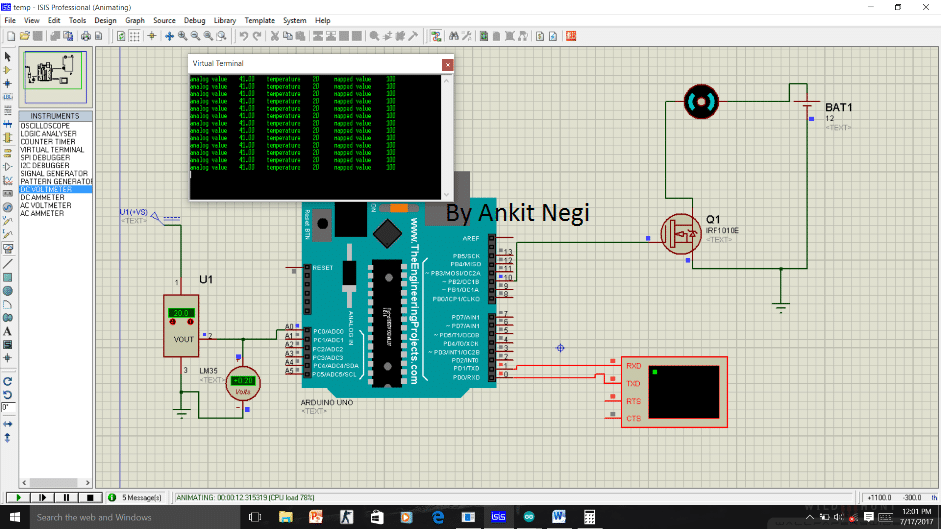
As you can see temperature is 20 degree hence
Analog value=41
Temperature=20
Mapped value=100
But since temp is less than 25 degree hence mosfet gets 0 volt as show in fig( indicated by blue dot).
CASE 2. When temp. Is greater than 25 degree
When temperature reaches 25 degree, then as specified in the code pwm signal is sent to the base of mosfet and with each degree rise in temperature this PWM voltage also increases i.e.
if(y>25)

{analogWrite(10,z*10)

} which is z* 10.
See simulated circuit in this case.

As you can see as temperature increases from 20 degree to all the way to 40 degree , all three value changes and at 40 degree Celsius
Analog value=82
Temperature=40
Mapped value=200
Since temp is greater than 25 degree hence mosfet gets corresponding PWM voltage as show in fig( indicated by red dot).
Hence motor starts running at 25 degree and with corresponding rise in per degree temperature; pwm voltage from pin 10 to base of mosfet also increases. Hence motor speed increases linearly with the increase in temperature and becomes almost maximum for 40 degree Celsius.
If you have any further queries regarding the above explained automatic temperature controlled dc fan circuit using fan and Arduino, you can always use the comment box below and send your thoughts to us. We will try to get back at an earliest.


Questions & Answers
THANKS for your kind information,SIR.
If it’s a PPM to PWM converter then I’ll give a try. Otherwise a continuous rotation servo may work fine.
Again a hearty thanks…….
K. Kausik
No problem Kausik, wish you all the best!
‘PRANAM’ SIR,
After a long interval I’m here with hearty greeting and a request.
I need to control a relay or a dc motor with PPM (not PWM !) signal from a rc receiver (like Flysky fs i10).
Actually there is 10 rows of 3 pins, ppm signal, +5v supply and ground in the receiver.
A servo motor can be easily controlled but a dc motor?
I came to know a kit from you tube videos (I don’t know how to send attachments, screen shot ) but in practical I didn’t find anything over internet.
I need a circuit or any link from your website.
Thanking you ,
K. Kausik
Thank you Kaushik,
PPM controller can be easily built using an IC 555, but I could not understand what you exactly want to achieve using PPM with motor or relay? If possible please elaborate.
Thanks for reply,SIR,
Actually I wish to start and stop OR engage a relay with ppm signal achieved from a rc quadcopter receiver, for flower dropping system or anything.
Eagerly waiting for your reply…????
Thanking you ,
K. Kausik
Hi Kaushik, you can make two IC 555 modules, one astable and one monostable. Then connect the monostable’s pin#2 with the pin#3 of the astable….Once this is configured then you can use monostable’s pin3 to get the PPM….which will depend on the frequency of the astable. The pulse width will depend on the monostable’s RC values.
Hi Swagatam
Thank you for the tutorial which was very informative. In my case I am using an lm35 and a 4 wire PWM 12DC fan, not requiring the mosfet. Should the same code work in this case. I am going to try it to see ,Just not sure if it should be modified.
Thanks Eugene
Eugene, I am not sure how the 4 wire fan could be configured with the last circuit in the above article, so I can’t suggest much whether the same code could be used for your specific application or not.
What component changes are needed if using a 5V fan in the first drawing? Also it would be useful if you could use a zoomable drawing (e.g. pdf) since the lettering is difficult to read.
You just have to replace the 12V supply with 5 V supply (battery)
here’s the enlarged image:
C:\Users\Sri Krishna\Documents\Arduino\fan\fan.ino:1:17: fatal error: dht.h: No such file or directory
i am getting this error when i try compiling ur 1st program,please help
thanks
It may be due to a missing library, or existing library not matching with dth11
Google search with the following phrase: fatal error: dht.h, you will be able to find many forums discussing this issue!
Good innovation Mr. Swags.
Can you please send a book of learning ARDUINO Programs/Codes.
Thank you very much.
Thanks Sasa, I tried to send it to your email, but it seems your email ID is not correct or has problems. It was returned back to my email.
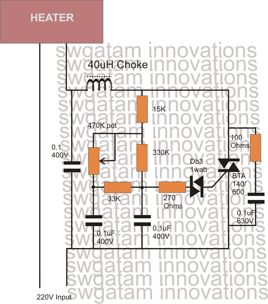
Hi
I have heater but I have to manually turn it on off when its cold. Can you suggest me a simple solution which will keep the room temperature warm throughout night. I intend to use this only in winter.
thanks
Bhargav
This would be better design if it also included humidity as a variable. I want a circuit that will activate relay when humidity is at 45% or less and when outside temps drop below ambient temp. So when both conditions are met relay is activated
you can refer to the following post:
https://www.homemade-circuits.com/2016/07/digital-temperature-humidity-meter.html