The circuit described here can be built and used in your vehicle for an automatic dipping and dimming operation of the vehicle headlamps, in response to the intense lights coming from an opposite vehicle headlamps.
What's a Dimmer/Dipper in Automobiles
An automobile headlight dimmer/dipper is a circuit which automatically switches the headlight intensities of vehicles arriving from opposite directions in a controlled manner.
This prevents the drivers from the blinding glares of the opposite side headlights, and allows the drivers to have proper control of their vehicles, and avoid serious accidents.
Why an Automatic Headlight Dimmer/Dipper is so Important in Vehicles
You must have come across this irritating situation while driving at night when you find the headlight lamp focus from an opposite vehicle coming straight to your eyes, making things difficult to assess, and giving rise to a situation of a collision or a possible accident.
Incidentally, the driver of the opposite vehicle might be going through the same situation due to the headlight focus from your vehicle.
Such situations are normally tackled by using manual dipper switch mechanism, where the driver is prompted to "dip" the focus of his headlight, thus giving the opposite vehicle a chance to adjust his vehicle and also an indication that he too needs to "dip" his vehicle lamps.
However, doing the above operation manually, every now and then can become horribly laborious and troublesome, therefore if some kind of automatic system is Incorporated, can help to save this headache of the driver, especially while he is driving in stressful conditions and on dangerous highways.
You maybe also interested in reading a PWM based self-adjusting dimmer/dipper circuit
Circuit Operation
The following diagram describes a simple yet effective auto head lamp dipper or dimmer circuit.
The transistor is used as a comparator, which compares the preset resistance level and the LDR resistance level with reference to ground.
Circuit Diagram
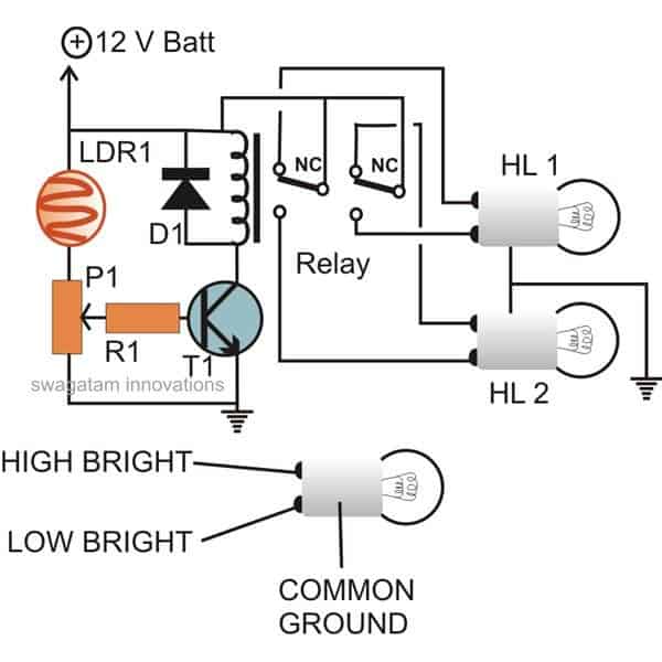
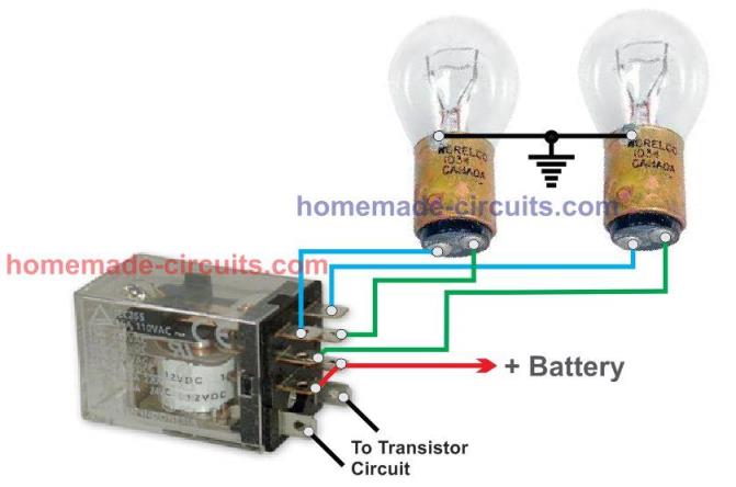
DPDT Relay Connection Diagram with Dipper Bulb
How the LDR Operates
Light falling over the LDR from the headlight of the vehicle coming from the front instantly lowers its resistance and allows more current to flow to the base of the transistor.
The transistor conducts and activates the relay, which in turn flips the contacts such that the host vehicle's headlamps gets connected with the dipper filament, changing its intensity.
The whole circuit may be enclosed in a small box and installed somewhere near the driver's dashboard area, however the LDR needs to be wired and placed out of the enclosure, in some corner of the wind shield, so that it is able to "see' the light from the opposite vehicles just as the driver would see them.
Parts List
R1 = 1K,
P1 = 10 K,
LDR = With resistance @ around 10 to 50 K when illuminated in daylight (under shade).
T1 = BC547,
D1 = 1N4007
Relay = coil 400 Ohms, DPDT, 12 volts
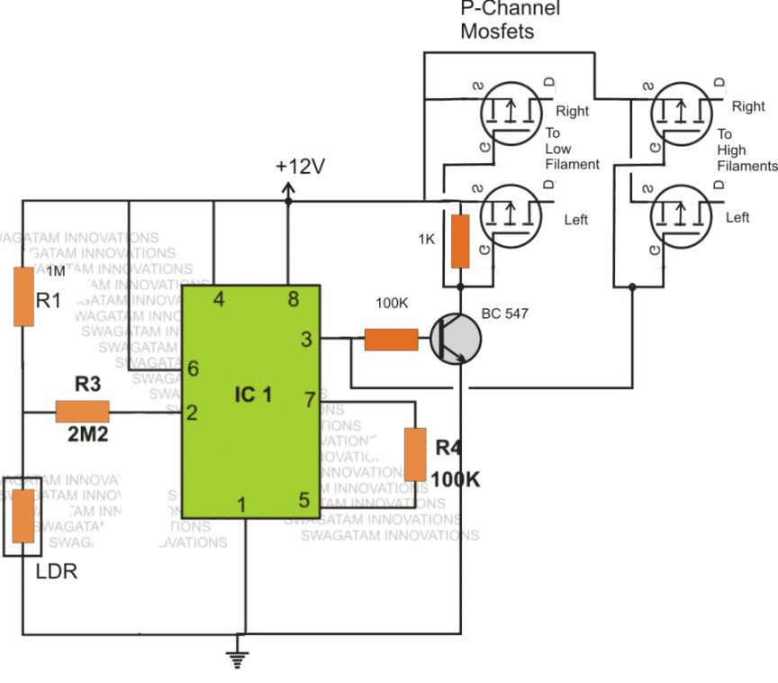
Making a vehicle dimmer/dipper without Relay
The above automatic dipper circuit can be modified for operating with mosfets:
Dimmer Dipper with Cellphone Charger
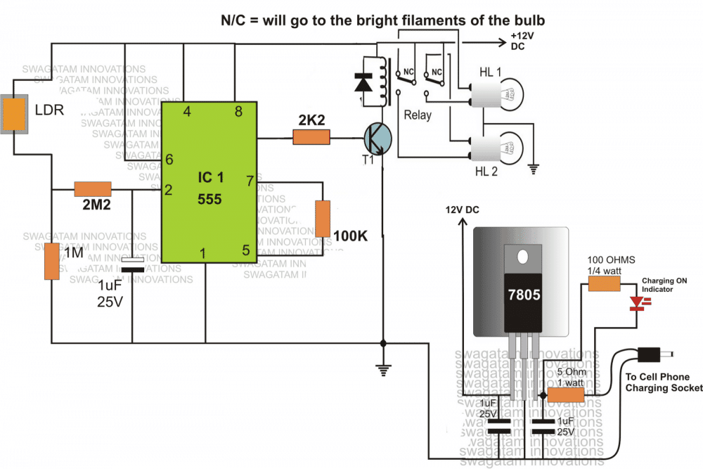
The following brief explanation was provided by Miss Surya for getting a better view of the proposed circuit design of an automobile dimmer/dipper head light switch circuit with an optional cell phone charger circuit for facilitating the charging of a cell phone also on board.
Circuit Operation
Here the IC 555 has been used not as a charging indicator rather as a comparator for controlling the dipping action of the head lamps.
The use if IC 555 as a charging indicator would have made the circuit unnecessarily complicated, therefore a novel and simpler way is selected for the charging ON indication.
The LED connected across the 5 Ohm watt current limiting resistor effectively indicates the charging status of the cell phone and switches OFF the moment the charging process stops.
The IC 555 works like a comprartor here, when light falls on the LDR, voltage at PIN#2 rises above the set internal threshold which prompts the IC to change its output PIN#3 voltage from 0 to 12, triggering the connected relay.
The relay contacts immediately transfer the positive supply from the "high" filament to the "low" filament of the head lamps, resulting in an instant dipping of the lamp intensity.
The LDR must be positioned in such a way that it only receives light rays coming from front of the vehicle, which will be mostly the lights from another vehicle's head lamps.
When we are using the IC 555 in comparator mode, it depends on the two important reference voltages to change its output:
- Trigger Voltage (Vtrigger): This is the voltage at pin 2, which is the inverting input. When this voltage drops below a certain level then it causes the output to switch from high to low.
- Threshold Voltage (Vthreshold): This is the voltage at pin 6 known as the threshold pin. When this voltage goes above a specific level then it makes the output switch from low to high.
Key Voltage Thresholds:
Trigger Voltage (Vtrigger): The output will switch from high to low when the voltage at pin 2 (the inverting input) falls below one-third of the supply voltage (VCC). We can express this as:
Vtrigger = (1/3) × VCC
Threshold Voltage (Vthreshold): On the other hand, when the voltage at pin 6 (the threshold pin) rises above two-thirds of the supply voltage (VCC), that’s when the output changes from low to high. We can write this as:
Vthreshold = (2/3) × VCC
Hysteresis in Comparator Mode
When we use the 555 timer with hysteresis, which is usually done by adding some positive feedback to pin 5, then the way the comparator switches becomes a bit less sensitive to tiny changes in the input signal.
This is really helpful because it helps prevent any noisy or erratic switching making everything run smoother.
So how does this hysteresis effect work? We create it by connecting a resistor between the pin 5 and the threshold pin (which is pin 7), in the above diagram it is 100k.
This setup forms a feedback loop that shifts both the trigger and threshold voltages. As a result we end up with two different voltage levels for switching the output which makes the comparator much more stable.
Here is what exactly happens in this case:
- Vtrigger (with hysteresis): When the input voltage at pin 2 drops below the level set by the hysteresis feedback, that is when the output will switch from high to low.
- Vthreshold (with hysteresis): Conversely when the input voltage at pin 2 goes above the level determined by the hysteresis feedback, the output will switch from low to high.
The feedback voltage which we call Vfeedback is given by the ratio of the resistors in that feedback network.
Using Photo Transistor
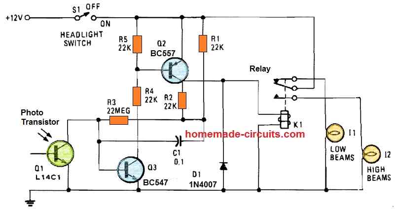
When photo-transistor Q1 detects the headlights of an approaching vehicle, the circuit gets operational and starts executing the dimming/dipping function.
The 22 M resistor, R5, sets the sensitivity to approximately half a foot-candle. A 12 V, 0.3A coil is utilized for the relay.
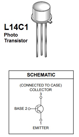
The photo transistor L14C1 comes with an one-inch lens with a 10° angle of view and a 1 inch diameter.



Questions & Answers
Hew to design all components . And decide it’s values
How to Connect the Diode to the Relay?
Do you have any Tutorial on making it?
The diode should be connected across the “relay coil” terminals. The cathode side connection will go to the positive supply, and the anode side will go to the transistor collector.
Thank you for your time
Yes what should be done on the headlamps
The negative pulse is provided by the alarm system, which behaves as follows: negative pulse output on unlocking and negative pulse output on locking .
Here’s the circuit you can try:
Thank you very much,
I will tru this circuit while waiting for ideas for a circuit combining serval lightning fonctions.
Sure, no problem!
OK, I will try to design them soon…
Hi,mr swagatam, first of all, I would like to congratulate you on your achievements, which are very, very useful!
I have a request to make regarding the automatic lighting circuit (which I have already made thanks to you)
I want to make a circuit combining several features!
1 – automatic lighting of the lights at night when unlocking the car with the alarm ( negative pulse) and turning off when the contact is put on.
2 – extinguishing the lights after a certain time after stopping the engine (delay)
3 – coming home/leaving home function only when it’s dark
Note: my alarm has several power latching and delayed output functions I send you the alarm schema if you want.
Thank you for your help and good luck <3
Thank you Mino,
On which lamp these needs to be done? Is it the head lamps.
The 1st one looks difficult since I do not know from where I should extract the trigger pulse.
Hi, please let me know the suitable position for the photo transistor?
Is there is any chance to interfere with street light or any other side lights?
Is that possible to build a flashing of high beam in case the opposite vehicle is not dimming there headlamp?
Hi, you will have to enclose the light detector inside a suitable pipe like encloser so that it is able to “see” only the light beam focused from the front vehicles. Yes it is also possible to flash the high beam bulb after a few seconds, through an additional circuit.
What are the components for this Project..
Please reply me..
Can u support to figure it out .Also am looking of a headlamp auto leveling system but not available in the market. I hope you can support me on that as well.
Some high end vehicles having that system but it’s bit complicated but I was looking for a simple one with the support of an inclinometer.
I will try to figure it out soon. Yes auto adjusting is also possible through a PWM circuit!
The values are given in the diagram itself
, nice one please can you explain to me how it works please
Hello sir, we made college project of “automatic headlight dim and bright controlled using ldr” from ur first ckt Diagram.. For 4 wheeler… Are u suru it really works? Pls sir reply its too imp for us..
Thank u so much for ur reply… And I hope it really work for me
You are welcome!
Hello Project Group, as you can see the design is very basic and therefore it will work exactly as described without any problems.
To ensure that the relay does not stutter at thresholds you can add a 1000uF/25V capacitor in parallel to the relay coil or the diode D1.
Test the circuit on your work bench using flashlight first, before actually installing it in a vehicle.
To make the circuit more sensitive you can upgrade the transistor into a Darlington transistor by adding another BC547 to it.
I would like to have a detailed circuit design using relay…
rezdude07@gmail.com
May be two vehicles have headlight with different intensity .like 2 car uses two types of light one is led and other is halogen in this situation is it possible
the circuit will respond to all forms of light, it doesn’t matter whether it is from LED or halogen….
Pls help to do dis idea for our project
what is your question?
We r try to do this idea as our project so pls help and support
Sir could you please explain the working of mosfets in the circuit…
and what is the use of 100 K resistor between 5 and 7 terminal of ic555
Give the complete details about this circuit
Email: iamamalvijayan9597@gmail.com
Amal, the mosfets are configured to act like SPDT switches, when the right side mosfet pair is ON, the left side pair is off and vice versa.
the 100K is to create some hysteresis effect between the ON OFF switching
place the LDR inside a short pipe, such that only light beams coming from the front is able to reach the LDR, and no other light from around or top.
LDR and photosensor will behave in the same manner, the correct way is to put the sensor inside a pipe like enclosure
Please give circuit diagram of relay point
I have updated the diagram in the article, please check it out
Can i install this automatic dipper in a scooter?
yes you can
Arduino version is possible, I have already built it…
Muhammad can u plz forward it to me!! My email is moluguvirat@gmail.com Thank u
Mohammad, please send me the details in my email: admin @ http://www.homemade-circuits.com
Hello sir, can you please post a circuit of AUTOMATIC HIGH BEAM TO LOW BEAM HEADLIGHT USING ARDUINO. with components required!! plz help me.
….sorry the arduino version will not be possible…
Surya, all the details are given in the article, please click the diagram to enlarge.
you can write the details on paper and show it to the part dealer he will do the needful
Sir I'm in a need of ur ckt diagram with components to complete my project. My last date of submission is Oct 21st. So please reply me with the complete details of it, as soon as possible sir. Plz sir. Thank you
Sir try to produce as soon as possible. Thank you sir.
Hello Surya, if possible I'll try to produce it in my website
which bulb is use for this..
What type battery and bulb should be used while submitting as an mini project sir pls kindly requesting u to answer me its urgent
power could be from a 12V /1amp ac dc adapter
For a realistic look you may want to procure an actual car headlight lamp with double filament, however if you find it difficult then you may simulate the same by tying two small DC bulbs together and wire them up as shown in the first diagram.
The Dim bulb could be a 24V bulb and the bright bulb could be a 12V bulb…
Hi . Im trying to build automatic headlight beam by using arduino mega 2560 to program the circuit diagram, i want to know if anyone can help me for a clear circuit diagram (12v input)or the connection i mean how to connect arduino to the circuit diagram
if possible we'll try to get it and post it for you
austin,
In the second 555 circuit do the following changes:
remove all the transistors and the pin3 100k resistor.
now connect white LEDs across positive and pin3, and pin3 to ground
use 10k series resistors for the ground LED and 1k for the positive LED
that's it, now the LEDs will respond like dipper lights