• Skip to main content
  • Skip to primary sidebar

Homemade Circuit Projects

Get free circuit help 24/7

Circuits for Beginners | Basic Circuits | LED Driver | Hobby Circuits | Transistor Circuits

New-Projects | Privacy Policy | About us | Contact | Disclaimer | Copyright | Videos

You are here: Home / Car and Motorcycle / Make this Car Interior Light Fader Circuit

Make this Car Interior Light Fader Circuit

Last Updated on January 1, 2019 by Swagatam 7 Comments

ask questions through comments

The post explains a simple circuit which can be used for producing a slow fading light effect each time it's switched OFF. The application can be typically used in car interior lights.

Designed by: Abu-Hafss 

The Circuit Concept

Most of the modern cars are equipped with circuitry which switches on the Car's room lamp when a door is opened and switches off the lamp in fading manner when the door is closed.

Here a simple circuit is presented which can be installed in old cars without any major alterations to get the same effect.

Before we understand the description of the circuit, it is important to understand the wiring of a Car's interior lamp and how the door switches are operated.
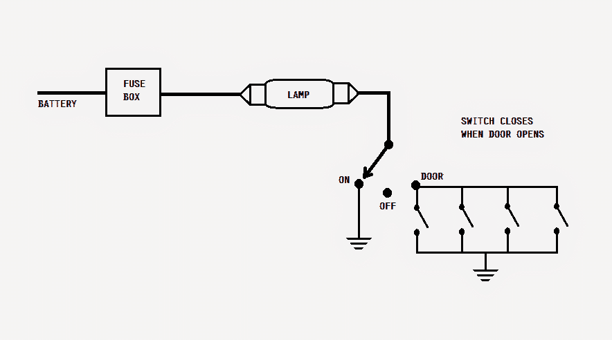
The lamp is connected to the battery's positive thru a fuse. The other end of the lamp is connected to a single-pole-3-throw switch.

When this switch is positioned at ON, the other end of the lamp gets connected to ground i.e. the negative terminal of the battery hence, the lamp gets illuminated.

In OFF position, the lamp remains disconnected from the ground. In DOOR position, the lamp gets connected to the ground via door switches (in parallel). When a door is opened, the corresponding door switch is closed.
How it Works

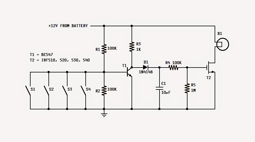
Referring to the proposed car interior light fader circuit, when any of the door is opened, its switch is closed hence, the base of T1 gets connected to ground and thus stop conducting. In this state, C1 gets charged rapidly via R3 and D1.

As soon as C1 is charged, the mosfet is fed with the gate voltage thru R4 and thus it starts conducting and consequently the lamp is illuminated.

Now, when that door is closed, its switch gets open. The base of T1 gets disconnected from the ground and is held at a voltage delivered by the R1/R2 voltage divider.

This action switches on T1, and the voltage coming from R3 finds it way to ground thru emitter of T1.

The switching on of T1 deprives C1 of its charging current and thus C1 starts discharging slowly thru R4 and R5. The gate voltage of T2 reduces as C1 discharges.

With this reduction in the gate voltage the intensity of the lamp is also reduced. Finally, when the gate voltage goes below the threshold voltage the lamp switches off.

The values of R5 and C1 are responsible for the fading delay time of the lamp. Increasing the values will increase the time and vice versa.

T2 should be any suitable N-channel mosfet capable of handling at least 50V and 10A. The whole circuit can be built on compact sized general purpose board and enclosed in the room lamp cover.

get free help for circuit diagrams

You'll also like:

  • 1.  Pedal Speed Controller Circuit for Electric Vehicles
  • 2.  Motorcycle Regulator, Rectifier Tester Circuit
  • 3.  Build a Homemade GSM Car Security System
  • 4.  Battery Charger for Positive Earth Cars
  • 5.  Car Turn Signal Flasher Circuit with Lamp Malfunction Indicator
  • 6.  How to Connect Car LED Downlight

About Swagatam

I am an electronic engineer (dipIETE ), hobbyist, inventor, schematic/PCB designer, manufacturer. I am also the founder of the website: https://www.homemade-circuits.com/, where I love sharing my innovative circuit ideas and tutorials.
If you have any circuit related query, you may interact through comments, I'll be most happy to help!

Subscribe for the Latest Posts


Reader Interactions

Comments

    Have Questions? Please post your comments below for quick replies! Comments should be related to the above artcile Cancel reply

    Your email address will not be published. Required fields are marked *

  1. Patrick says

    August 17, 2020 at 7:51 pm

    Hi Swagatam,
    Just one more question if you don’t mind? What transistor do you recommend for my application?
    Thanks again for all your help so far
    Regards
    Patrick

    Reply
  2. Patrick says

    August 16, 2020 at 12:32 am

    Will this circuit also work with an led light. ie for the ignition switch so you can see where to put the key at night. I am thinking just one LED. Thank you for your kind assistance. Regards, Patrick

    Reply
    • Swagatam says

      August 16, 2020 at 9:10 am

      Yes sure, just replace the lamp with an LED having a series 1 K resistor.

      Reply
      • Patrick says

        August 17, 2020 at 6:19 pm

        Thank you very much Swagatam. I appreciate your help and advice. I will try this circut and see how to make the timing 10 seconds by playing with the capacitor and resistor combination. I have som small N channel mosfets which I will try. I doubt that I need a 10 amp mosfet for a single LED.
        Thanks again.

        Reply
        • Swagatam says

          August 18, 2020 at 9:38 am

          Thanks Patrick, yes for an LED a 10 amp transistor will not be required, you can use a BC547 instead.

          Reply
          • Patrick says

            August 18, 2020 at 1:15 pm

            Swagatam,
            Thank you for the answers to my questions. As you will no doubt have gathered that I am not very knowledgeable with electronics so I find it very helpful that you and people like yourself go to the trouble of helping people like myself and I am very grateful. I have lots of BC547’s in my box so I will breadboard the circuit today and let you know how I get on.
            Regards
            Patrick

            Reply
            • Swagatam says

              August 18, 2020 at 5:33 pm

              No problem Patrick, please go ahead!

              Reply

Primary Sidebar


Categories

  • 3-Phase Power (15)
  • 324 IC Circuits (19)
  • 4017 IC Circuits (52)
  • 4060 IC Circuits (25)
  • 555 IC Circuits (98)
  • 741 IC Circuits (19)
  • Amplifiers (59)
  • Arduino Engineering Projects (83)
  • Audio Projects (94)
  • Battery Chargers (83)
  • Car and Motorcycle (94)
  • Datasheets (46)
  • Decorative Lighting (Diwali, Christmas) (32)
  • DIY LED Projects (89)
  • Electronic Components (97)
  • Electronic Devices and Circuit Theory (35)
  • Electronics Tutorial (109)
  • Fish Aquarium (5)
  • Free Energy (34)
  • Fun Projects (12)
  • GSM Projects (9)
  • Health Related (19)
  • Heater Controllers (28)
  • Home Electrical Circuits (100)
  • How to Articles (20)
  • Incubator Related (6)
  • Industrial Electronics (28)
  • Infrared (IR) (40)
  • Inverter Circuits (98)
  • Laser Projects (12)
  • LM317/LM338 (21)
  • LM3915 IC (25)
  • Meters and Testers (64)
  • Mini Projects (156)
  • Motor Controller (66)
  • MPPT (7)
  • Oscillator Circuits (24)
  • PIR (Passive Infrared) (8)
  • Power Electronics (33)
  • Power Supply Circuits (74)
  • Radio Circuits (9)
  • Remote Control (47)
  • Security and Alarm (61)
  • Sensors and Detectors (118)
  • SG3525 IC (5)
  • Simple Circuits (74)
  • SMPS (29)
  • Solar Controllers (60)
  • Timer and Delay Relay (53)
  • TL494 IC (5)
  • Transformerless Power Supply (8)
  • Transmitter Circuits (40)
  • Ultrasonic Projects (14)
  • Water Level Controller (45)


Circuit Calculators

  • AWG to Millimeter Converter
  • Battery Back up Time Calculator
  • Capacitance Reactance Calculator
  • IC 555 Astable Calculator
  • IC 555 Monostable Calculator
  • Inductance Calculator
  • LC Resonance Calculator
  • LM317, LM338, LM396 Calculator
  • Ohm’s Law Calculator
  • Phase Angle Phase Shift Calculator
  • Power Factor (PF) Calculator
  • Reactance Calculator
  • Small Signal Transistor(BJT) and Diode Quick Datasheet
  • Transistor Astable Calculator
  • Transistor base Resistor Calculator
  • Voltage Divider Calculator
  • Wire Current Calculator
  • Zener Diode Calculator


You can also Chat with me here:

Facebook
Twitter
YouTube
Instagram
My Facebook-Page
Quora


© 2022 · Swagatam Innovations

We use cookies on our website to give you the best experience.
Cookie settingsAccept All
Privacy & Cookies Policy

Privacy Overview

This website uses cookies to improve your experience while you navigate through the website. Please visit the Privacy Policy Page for more info.
Necessary
Always Enabled
Necessary cookies are absolutely essential for the website to function properly. This category only includes cookies that ensures basic functionalities and security features of the website. These cookies do not store any personal information.
Non-necessary
Any cookies that may not be particularly necessary for the website to function and is used specifically to collect user personal data via analytics, ads, other embedded contents are termed as non-necessary cookies. It is mandatory to procure user consent prior to running these cookies on your website.
SAVE & ACCEPT