The following circuit was requested by one of the readers of this blog Mr. Keval. The actual request was for a rain triggered windshield wiper circuit, but the idea here has been further enhanced with a quick start feature for better efficiency.
How Conventional Wiper Systems Work
Normally, electronic wiper control circuit involve a bistable for switching the wiper mechanism into an oscillatory action.
The bistable switches ON the wiper motor and keeps it moving until the set time lapses, this process continues for so long the power is switched ON to the circuit.
A 555 IC is fundamentally utilized for implementing this function, which is generally configured in it standard bistable mode. However one disadvantage with a standard 555 bistable circuit is that it introduces a delay of of around 1.6 times the set RC time interval value.
Therefore if suppose the bistable delay is set to 10 seconds would mean a 555 bistable would require a 10*1.6 = 16 seconds to initiate the action, that can be very annoying.
Enhancing an Instant Start Action
The present design eliminates the above issue by wiring the 555 bistable in a smart way.
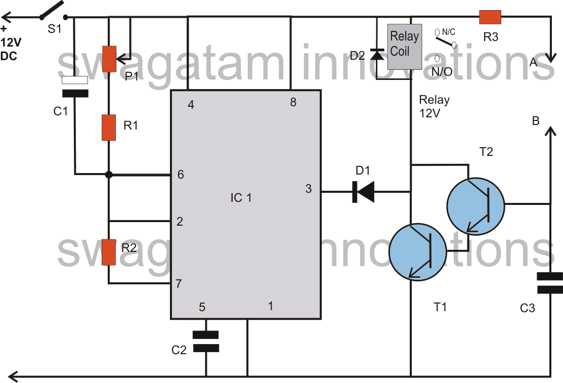
Referring to the circuit diagram, when the wiper switch S1 is depressed, pin#6 of the IC is immediately elevated to the supply voltage level of 12V via C1.
This resets the bistable, making its output go low, which energizes the connected relay and the wiper motor gets instantly activated.
The above process of instantly starting the motor using a 555circuit makes the present circuit different from the conventional circuits which employs the same IC but without the above modification.
Now once C1 is charged, which happens via R2 after the output gets activated, pin#2 of the IC falls below the 1/3 Vcc mark. This situation pulls the output to high, switching OFF the relay and the system.
After this C1 starts discharging through R1 and P1, once C1 completely discharged the cycle is yet again repeated as long as S1 is kept depressed.
The value of R1 and the setting of P1 decides the OFF time of the circuit.
If the value of P1 and R1 is selected too low, then C1 may not get charged solely through them but also via R2, which will make the output and the relay system to stay switched ON forever, until S1 is switched OFF.
Adding a Rain Trigger
An useful rain trigger feature can be added to the circuit for enabling an automatic start of the wiper motor when rain fall is detected.
The two transistors T1 and T2 are configured as a high gain amplifier set up. The points A and B get bridged with rain water droplets introducing a low resistance across the points.
This switches ON the transistors and the relay, which in turn switches ON the connected wiper motor.
The wiper motor remains switched ON as long as rain persists and points A/B stays bridged with water droplets.
Circuit Diagram
Parts List
R1 = 47K,
R2 = 22K,
R3 = 1K,
P1 = 1M
C1 = 33uF/25V
C2 = 0.01uF
C3 = 0.1uF
D1,D2 = 1N4148
T1,T2 = BC547
IC1 = 555
RELAY = 12, SPDT
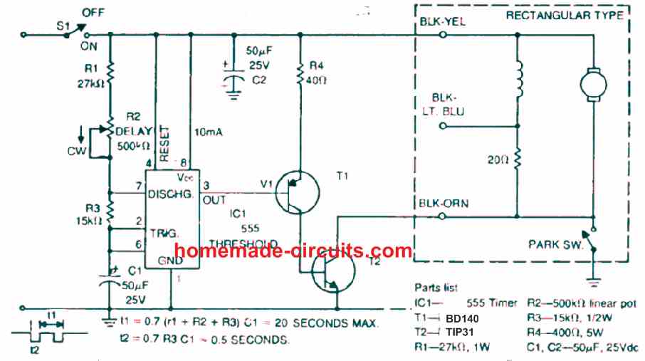
Adjustable Windshield Wiper
The following IC 555 based windshield wiper facilitates the driver to control the wiper seed manually, and adjust the wiper action to any desired speed.
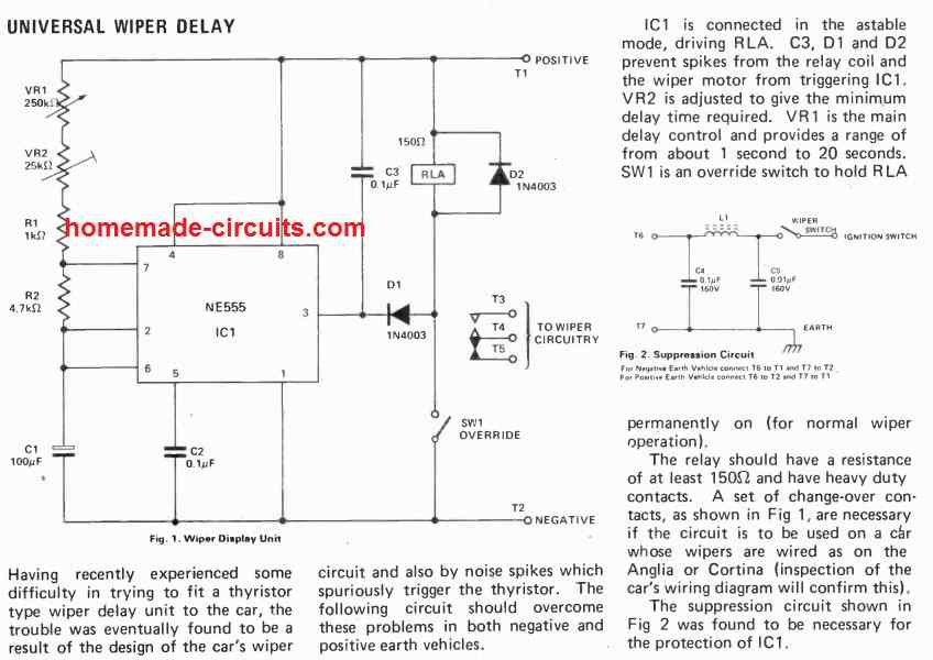
Wiper Delay Circuit
Another Simple Car Wiper Controller
U1 is set to work in the usual astable mode, which acts as a relaxation oscillator. Once power is supplied, C2 charges to 2/3 of the supply voltage via R1, R2, and R3. U1 detects that its pin6 threshold voltage is exceeded at this moment, and the timer is triggered, prompting its output at pin 3 to become high. When such high logic is supplied to Q1's base, the transistor remains in the off state. C2 now starts to discharge to pin 7 of U1 via R2.
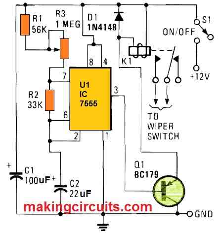
U1 is switched back to its original state once C2 has drained to roughly 1/3rd of the supply voltage. As pin 3 of U1 drops low, C2 begins to charge afresh. Q1, which acts as an emitter-follower buffer stage, turns on when pin 3 is low, enabling current to pass across the coil of relay K1. As a result, Kl's contacts close, providing power to the car wipers. The setting of potentiometer R3 determines the charging time of capacitor C2. Tantalum capacitor C2 is recommended, although virtually any 12 V coil relay with suitably heavy duty contacts would suffice.


Questions & Answers
Hi.
Presumably, the A nad B contacts are in a position to get wet, but also to be wiped by the windscreen wipers? Or does it rely on evaporation to clean the water from the contacts?
If it relies on the wipers cleaning the contacts, does the circuit make 2 or 3 sweeps after the water has been cleaned?
I assume the best place to mount the contacts would be in the path of water that has been swept from the screen?
Just some thoughts…
Hi, The A and B do not need to be situated on the windscreen, instead they can be set a little away, where it is able see the rain. Alternatively, the sensor could be installed inside a tube with a small hole at the bottom. So the tube remains filled as long as there’s rain, and when the rain stops, the water gets drained from the hole disconnecting the A and B points.
sir one doubt..i think this circuit works only when water is in contact between a&b..when water leaves it stops
NVD, yes that's right, the water sensing option makes the circuit automatic, while the switch provides the manual option, so the circuit is facilitated with both the options here.
Sir I am jitendra. I'm making a large scale helicopter so can u please help me in making its rc circuit board.
Hi Jitendra, I will try to publish it soon….