An electronic device or circuit which detects and indicates the various fuel levels in a fuel tank without a physical contact, through ultrasonic waves, is called an ultrasonic fuel level sensor
In this post I have explained how to build a simple fuel tank level indicator circuit using Arduino and ultrasonic sensors.
In every vehicle the fuel tank is probably the most important part of the entire system, since the vehicle's operation critically depends on the presence of the tank fuel.
This also means that monitoring the fuel level in the tank becomes an essential factor for the owner or the driver of the vehicle.
Although, most vehicles are already equipped with an advanced digital fuel sensor indicator device, building your own circuit can be a lot of fun and satisfaction.
Warning: This project is only for experimental purpose. It must be done under expert supervision, if actual fuel is used for the tank fluid.
In this article I have explained how to build an LED based fuel indicator circuit using GSM wireless ultrasonic sensors and Arduino.
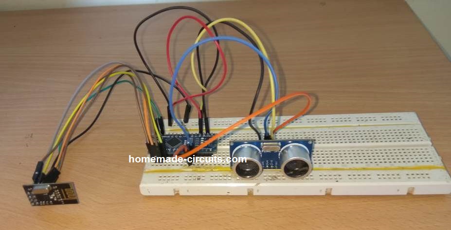
Ultrasonic Fuel Sensor Transmitter
To build the transmitter circuit, you will need the following modules:
- Arduino NANO - 1no
- Ultrasonic sensor module HC-SR04 - 1no
- nRF24L01 wireless Tx/Rx module - 1no
After programming the Arduino, the modules will have to wired as shown in the following diagram:
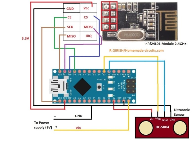
The white table at the top left shows how the pinouts of the nRF24L01 module needs to be connected with the Arduino board.
How it Works
As we can see, there are a pair of ultrasonic sensors in the module. One senor sends the ultrasonic frequency or the wave towards the fuel surface. The waves collide with the fuel surface and reflect back towards the module. The reflected ultrasonic waves are captured by the second sensor unit, and sent to the Arduino.
The Arduino compares the reflected ultrasonic time with the reference time of the tank "full height" and creates an estimation of the instantaneous height or the level of the fuel.
The information is then encoded and forwarded it to the nRF24L01 wireless module. The nRF24L01 module finally converts the code into RF signal and transmits it into the atmosphere for the receiver unit to capture the signal.
How to Mount the Sensors
Once assembled, the ultrasonic sensor will need to be installed on the fuel tank in the following manner:
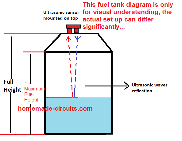
The ultrasonic sensor will need to be installed by inserting the sensing heads through perfectly dimensioned holes, and sealed with appropriate sealing agent.
We can see the tank is specified with two measures, one is the full height, and the other is the maximum or the optimal fuel height inside the tank.
You will have to note these two measures as these will be required to be entered in the program code for the Arduino.
Ultrasonic Fuel Sensor Receiver
For making the fuel sensor receiver you will require the following materials:
- Arduino NANO - 1no
- Ultrasonic sensor module HC-SR04 - 1no
- nRF24L01 wireless Tx/Rx module - 1no
- LEDs as shown in the following diagram - 4nos
- Piezo buzzer - 1no
- 330 Ohm 1/4 watt resistors - 4nos
Circuit Diagram
After programming the various modules may be connected in the following manner:
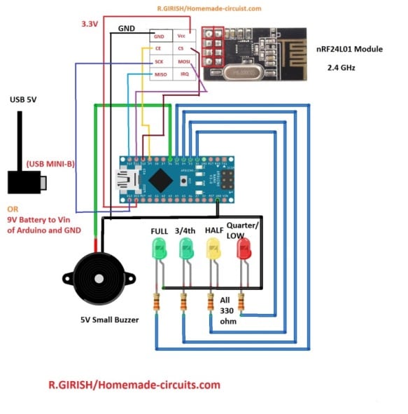
Here, the nRF24L01 wireless works like a receiver. The antenna captures the RF content transmitted by the transmitter circuit, and sends it to the Arduino. As per the program code, the Arduino analyzes the varying ultrasonic time, and translates it into an incrementing digital output.
This digital output which corresponds with the instantaneous height or the level of the fuel is fed into an LED array. The LEDs in the array respond and illuminate sequentially enabling a direct visual indication of the fuel level to the owner.
The green LEDs indicate a healthy condition of the fuel content. The yellow LED indicates that the vehicle needs a refueling quickly, while the red LED indicates a critical situation, regarding the fuel about to finish. The buzzer now starts buzzing creating the necessary warning alarm.
Program Code
The complete program code for the transmitter and the receiver can be found in the following link:
https://github.com/Swagatam1975/Arduino-Code-for-Fuel-Sensor
You'll need to Change the two example values in the code with the values that you measured for your fuel tank:
// ------- CHANGE THIS -------//
float water_hold_capacity = 1.0; // Enter in Meters.
float full_height = 1.3; // Enter in Meters.
// ---------- -------------- //
Useful Calculations
HC-SR04 Ultrasonic Sensor Distance Calculation
This sensor works by sending sound pulses and measuring the time taken for the echo to return.
Formula for distance:
Distance = (Speed of Sound * Time) / 2
- Speed of sound at 25°C: 343 m/s = 0.0343 cm/µs
- Time (t) is measured in microseconds by the Arduino.
Example calculation:
If time (t) = 1000 µs,
Distance = (0.0343 * 1000) / 2 = 17.15 cm
Resistor for LED Current Limiting
To calculate the resistor value for an LED:
R = (Vs - Vf) / If
Where:
- Vs = Supply voltage (e.g., 5V)
- Vf = Forward voltage of the LED (e.g. 2V for red LEDs)
- If = Forward current of the LED (e.g. 20 mA = 0.02 A)
Example calculation:
R = (5 - 2) / 0.02 = 150 Ω
Using a 330 Ω resistor limits the current further ensuring that the LED lasts longer.
Piezo Buzzer Frequency
To generate a tone the frequency is related to the time period:
Frequency = 1 / Period
Example:
To generate a tone at 1 kHz,
Period = 1 / 1000 = 0.001 seconds = 1 ms
Total Power Consumption of LEDs
To calculate the total power consumption of 4 LEDs we use the following formula:
Power = Vs * Total Current
If each LED uses 20 mA (0.02 A):
Total Current = 4 * 0.02 A = 0.08 A
Power = 5V * 0.08 A = 0.4 W
nRF24L01 Power Requirements
The nRF24L01 module requires 3.3V to operate and its current consumption is around 12-15 mA.
You must ensure that the Arduino Nano's 3.3V pin can supply sufficient current.

Questions & Answers
Nyc idea, sir i want use thisnproject as a water tank, can you grade code for moter auto on and off with water level, like once water low as required water moter pump start auto, and when water level near to sensor range moter shuts off. plz help me
Hi Ghulam, the above concept will need to be updated with a relay for the automatic motor operations, I will try to update the code soon…
hi sir, thank you sir, I am waiting……
Ghulam, I have updated the circuit here:
https://www.homemade-circuits.com/automatic-ultrasonic-water-level-pump-motor-controller-circuit/
thank you so much sir, I will try and update you.
You are welcome Ghulam,, let me know how it works..
Dear Sawagam, first of all thank you very much. But the pain of these modules is very wide and the stability is very bad. I have tried almost all of these module options. I need a more stable circuit that will not cause problems in the slightest fluctuation in the water. The Arduino part is not important. A healthy and strong circuit will be better.
Thank you Mert,
Currently I do not seem to find an appropriate circuit design that may fulfill your application with extreme accuracy, and designing this type of circuit without an Arduino or a microcontroller might not be feasible, according to me.
I will keep looking though, if I happen to find something similar, i will surely let you know.
Hello Kartikeswar,
Mr. Girish is unfortunately not available here at the moment.
Thank you for your message.
About our project, I have the following doubts:
1. Suppose we don’t consider sensor output as voltage and consider it as a simple digital value. Will it be easier for us to get the result?
2. You have used for testing, a battery. What volt is it? You must have made the volt meter compatible to the said battery?
3. My sensor’s output is less than 5 volts. Will this volt meter be compatible?
4. You have used one potentiometer. I have not understood the function of it in this volt meter project.
5. I want the display unit (LCD), to be 3 digit one, may be of one-inch x half inch. Because, enough space is not available on my bike dash board. If I take a bigger display unit, I have to make separate arrangement outside the dash board.
6. You have mentioned, fixed resistors. Do you mean, not variable resistor?
7. You have mentioned, resistors with minimum tolerance value. What does it mean? How do I buy it? In the shop, they don’t sell with tolerance value.
8. In the Arduino, there appear to be two batteries. What volt is it? Into the petrol tank, less than 5 volts is used. More voltage may be riskier? Bike has got 12 volts current. But the same is not given to the sensor.
9. You have mentioned about polarity. Where does it exist?
10. Which Arduino to be procured for the purpose?
After getting your reply, I will buy the Arduino and proceed. Thanks.
Hello Kartikeswar,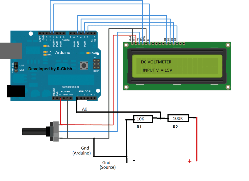
I guess you are referring to the following article:
https://www.homemade-circuits.com/how-to-make-dc-voltmeter-using-arduino/
Here are the answers:
1) I did not correctly understand this question. Voltage can be be converted to a digital value through a digital meter only. If the sensor output is a voltage then we must consider as voltage only.
2) The battery is a 9V battery which is used as a sample source for displaying the 9V through the Arduino digital meter.
3) Any voltage can be displayed by suitably adjusting the values of R1 and R2.
4) The potentiometer is probably for adjusting the brightness of the display.
5) The display cannot be changed, it will need to be exactly as shown.
6) Fixed resistor is referred to R1 and R2 which should not be adjustable type.
7) Tolerance value can be 1%, for example 10K 1% or 100K 1% etc.
8) No batteries are used in the circuit, you can recheck it here:
9) Polarity across R1, R2 where the input voltage is fed.
10) You can use Arduino Uno.
Sir,
Sorry for the delay. I got the signals in the form of voltage, though fuel meter is not giving correct result. Empty tank – 1.34 volt and full height of the tank 4.56 volt. (Maximum fuel height may be less.) Tank capacity is 14.5 liters. Will this help? But there is a problem. Sensor doesn’t get power directly; it gets through the analogue meter. So, in order to make the digital meter working, the circuit of the analogue meter must be intact. (circuit of the analogue meter appears to be ok but not sure). I think, I can give it a trial.
Alternatively, I think, I should try your Arduino+Ultrasonic Sensor. But I want to know, if the ultrasonic sensor will work if, it is fixed along with the existing sensor instead of making hole in the tank. Secondly, whether the Arduino is available ready made?
Thank you for the update Kartikeswar,
If the readings are consistent for each up/down cycle then the specified voltage readings can be used with a voltmeter for the indicating the tank levels accurately.
If the circuit is designed to get the supply through the analogue meter then a digital cannot be used I am afraid.
The arduino circuit is quite complex and is recommended only for the experts in the field.
If you think you can implement the above Arduino circuit correctly, then you can go ahead with it.
The Arduino board is available ready made but will need to be programmed with the given code.
Sir,
Thank you for your response. I was going through your circuit diagram of Arduino+Ultrasonic sensor. It is most appropriate but fixing the sensor on the top of the tank is the most difficult task. I think, I should try it later. In the mean time I would like to use the existing voltage changes for a digital meter. I came to know that through Arduino, changes in voltage can be decoded. Could you please tell, how is it possible and how to do it?
No problem Kartikeswar,
To measure voltage through Arduino, you can perhaps try the following concept:
https://www.homemade-circuits.com/how-to-make-dc-voltmeter-using-arduino/
Sir,
Your circuit is good, but practically difficult. what I wanted is that, the analogue fuel signal , which is already there in the bike is to be converted to digital signal and the result to be displayed on the LCD screen. This will be convenient to install. if you can do it, kindly give me the details. I am not a technical person and my bike’s fuel meter (analogue) is not working. So I want it to convert to digital. I got a project report about this but the details are not available. In this project, they have used PIC 16 F 877 A and a converter(Analogue to Digital). No other details are available.
Hello Kartikeswar,
Without seeing what kind of fuel sensor is already installed in your bike, it can be difficult to design a compatible converter circuit which will convert the signals into a digital readout. Please check what kind of signal you are getting from the existing setup in your bike.
Sir,
Thank you very much for your response. My bike has got analogue fuel meter, which is not in working condition. since it can not be repaired, I want to convert it to digital meter. As I had informed you earlier, I am a non-technical man. So I can not give you more details. Incidentally, I want to inform you that, I am also interested in your circuit on ceiling fan remote control. I studied the circuit and searching for the components. Some components are available online and about three are yet to be searched. I will try to do it. Once again thank you for your response.
Kartikeswar,
Without knowing what kind of output your analogue meter is generating it can be difficult to suggest a solution to your problem. The digital meter can be a frequency meter or a voltmeter, it will depend on the kind of output your analogue meter is designed to generate.
You can try the ceiling fan remote control. Let me know if you have any further questions.
Thank you very much for your response. I understand that, your work may be most perfect, because of which you may be needing an appropriate converter of analogue to digital. I am trying to find out the signal you want to know about. In the mean time, I want to inform you that, in the project, I talked before, they have given the diagram as Fuel tank>Analogue to Digital converter>PIC 16F 877 A> LCD. In another project, they have used HX 711, as the ATD converter. In Google search, they are mentioning about one IC741, as ATD converter. See, if these information will be helpful to you.
Thank you Kartikeswar, the PIC controller is the one which is difficult to design, and I do not have it with me at this moment. Anyway, if you are able to find what kind of analogue signal is available in your existing system, that might help to understand its functioning details.
Sorry for the interference if any. In continuation to my message of today morning, I want to add that, whenever the fuel tank is empty, there is high resistance and as the tank gets full, the resistance reduces, allowing more current to pass through the analogue meter which the meter displays. Therefore, we need a device to read this current variations. If you provide me with your email id or WhatsApp number, communication would be easier.
OK, if the output is in the form of a varying current then I think you can easily interface it with a digital ammeter to get the proportional readings. There are plenty of small digital ammeters available online which you can procure and get it installed in your bike.
Alternatively you can try the following Arduino based design for the same. The “load” points must be connected with the output from your analogue system.
https://www.homemade-circuits.com/arduino-dc-digital-ammeter/
We can discuss the procedures here, no problems, since it allows the other readers also to learn something new.
Your message doesn’t have a option to reply. As per your advice, I checked the socket. There is no any current. But while doing this, I confirmed that the sensor is defective. This sensor, was replaced in the bike’s service centre. When the meter didn’t work, they advised to get the entire dash board replaced. If I had listened to them also, meter would not have worked because of the sensor. Now, again I don’t want to go to them. I have to search for a suitable mechanic or do it myself. However, I am great ful to you as, because of you only I could discover the actual defect. So, a lot of thanks. After doing the sensor work, I may contact you. Bye till then. Thank you again.
I am really sorry to hear that! I hope a qualified auto mechanic is able to help you to solve this issue. Nevertheless, I am glad you found my suggestions helpful.
Wish you all the best! You can surely contact me back if you have any further queries.
Thank you very much for your response. Whatever information,I have gathered till now is that, in analogue meter, there is a variable resistor connected to a float. This resistor generates variable voltage, which is displayed in analogue meter. So, we need a device to read the voltage changes and display it on LCD. Is this information helpful to you?
OK great! In that case you can try implementing the following concept:
https://www.homemade-circuits.com/simple-arduino-digital-ohmmeter-circuit/
There is nothing to be sorry about. In fact, because of you only, I could gather information about the working of the sensor. And now, I have decided to repair the sensor myself since, no mechanic is available nearby. So, double thank you. Meter may work after the sensor is repaired. But, even in that case, I would like to put the digital meter as an additional feature. So, I will be in touch with you soon. Thanks for your support.
Thank you, I am glad I could help you!
I hope you are able to troubleshoot the sensor issue!
Let me know if you have any further questions.
Thank you very much for your reply. I will try to do what you have said and let you know the out come. There is no option of reply to your following message. So, I am replying like this. Thank you again.
It will not read the voltage, it will read the current. As you said, the fuel sensor output will send a varying current output, so the “load” points of the Arduino circuit can be connected with your fuel sensor probes for the reading the current.
You can first confirm using an ordinary digital multimeter in DC current range, connect the probes of the meter with your analogue output and check whether the meter reads the current or not.
Ok, thank you very much. I will try to check with multimeter. Actually, I don’t know, where that socket is (there is supposed to be a socket, connecting the sensor and the analogue meter). Tomorrow, I will go to the mechanic and get the socket removed. I understand, you are eager to know the result. Kindly bear with me. In fact, until I took interest in fan remote control, I was not unable to identify a resistor, transistor or diode. More over, I am about 70 years old. So, things are not that easy for me. Since, I don’t have any income, I search for cheaper options. However, I am more interested in making something myself and fortunately, I came across good people like you. Thanks a lot.
Sure, no problems at all! I appreciate your interest. I hope you will be able to succeed with the project soon.
Actually I provided my opinion as per your specifications regarding the analogue sensor. You said that the sensor has a resistance which generates varying current output, so using this information I suggested you to use an ammeter with your analogue sensor.
You can first try with a digital multimeter in the DC mA range and confirm the response.
Thank you very much for your mail. I tried to study the arduino. But could not find out, how it will read the voltage changes to display fuel level. It possible has a link to fuel meter, which can be found out by a technical man. Could you please clarify little?
It will not read the voltage, it will read the current. As you said, the fuel sensor output will send a varying current output, so the “load” points of the Arduino circuit can be connected with your fuel sensor probes for the reading the current.
You can first confirm using an ordinary digital multimeter in DC current range, connect the probes of the meter with your analogue output and check whether the meter reads the current or not.
HOW MUCH DOES IT COST, CAN YOU MAKE ONE FOR ME
Great job, but I have a question. What is the maximum distance it can detect? I have a fuel oil tank and at least it has to detect me 155cms, I suppose that this sensor is not viable? with the same circuit can I use another? Thanks.
I think 155 cms is quite feasible using this circuit. You can try it and check the response!
Thanks!
Hi.
I have freetime house with 12v solar power and controlling diesel heater on/off and temperature checking simply with Arduino/GSM.
How connect traditional resistive (10-180ohm) fuel gauge to Arduino input for checking fuel level in tank?
Question –
I have reservation about ANYTHING electronic in a fuel tank. So my questions are listed:
How do you keep spark from generating on ultrasonic sensors as the sensor deteriorates from age?
Fuel of any type will corrode most things – how do you keep the sensor, sensor wires and mounting from going bad?
When fuel hits the air saturation temperature how do you keep the circuit cool enough to keep the extra heat from igniting the fuel vapors in the air especially on empty tanks?
As you can see in the diagram, no part of the circuit is inside the fuel tank, even the sensors are outside. Moreover, since the entire circuit works with a low voltage DC, question of any sparking does not arise.
Hello Sir,
I’m very happy to find your website, it is a fantastic cache of information and is great for novices as well as more experienced technicians. I have some background in electronics, but it has been a long time since I’ve really used it, and I could use some help.
My inquiry is about the Ultrasonic Fuel Level Gauge, and I have a slight twist on the concept. I have a transceiver, DS1603L V1.0, that operates at 2Mhz, and it is capable of measuring the fluid level from below, affixed to the bottom of a metal fuel tank, with a detection range of a meter or so. It has a uart serial output, and I need to convert it to an analog voltage output for a standard 12v fuel gauge on my motorcycle. I bought it from Ebay, but they’re available on Amazon or AliExpress also.
An Arduino should be perfect for this, but I have no experience with these yet. Would you be interested in a little experiment and showing us how this might be done?
Thank you Beardly, unfortunately I too do not have an expertise in the field of Arduino, so I won’t be able to provide any help in this particular subject, although I wish I could!
Is there some form of signal smoothing, to try and eliminate signal variations due to fuel sloshing in the tank?
I don’t think that would affect the reading, because Arduino being a digital device will respond ony to the genuine peaks of the signal, and reject the lower undefined ones.
Still you can try connecting a 1uF capacitor across the ECHO pin and the ground pin.
I really appreciate your invention, but instead of the led indicators as the output signal can’t you upgrade it and use 16 x 2 LCD screen
You can upgrade it by reading the instructions as given in the following article:
https://www.homemade-circuits.com/learning-basic-arduino-programming-tutorial-for-the-newcomers/